Load Rating of Segmental Bridges (2024)
Chapter: 5 Guideline for Load Rating Concrete Segmental Bridges
CHAPTER 5
Guideline for Load Rating Concrete Segmental Bridges
5.1 Proposed Outline for the Guideline
This outline is based on earlier work on this topic by Corven Engineering (2004). The four load rating examples for different types of concrete segmental bridge construction are also included in Appendix C of the Guideline document, which has been sent to AASHTO for their consideration. These examples were developed during the project. In addition, the following sections of AASHTO LRFD (2020a) and AASHTO MBE (2020b) have been identified for proposed revision:
- AASHTO LRFD Bridge Design Specifications
- Section 3.4.1—Load Factors and Load Combinations
- Article 5.12.5.2.3—Analysis of the Final Structural System
- Article 5.12.5.3.6—Creep and Shrinkage
- AASHTO’s The Manual for Bridge Evaluation
- Article 6A.2.3.6—Temperature Effects: TG and TU
- Article 6A.4.2.2—Limit States
- Section 6A.5.11—Rating of Segmental Concrete Bridges
The outline for the Guideline is as follows:
1. Introduction
2. Load Rating Philosophy
2.1. General
2.2. Load and Resistance Factor Rating (LRFR) Methodology of MBE
2.3. LRFR Philosophy for Concrete Segmental Bridges
2.4. Inventory and Operating Rating Levels
3. Data Collection
3.1. Existing Plans
3.2. Construction Records
3.3. Inspection Reports
3.4. Maintenance Records
4. Analysis Requirements
4.1. Longitudinal Analysis
4.2. Transverse Analysis
4.3. Analysis of Local Details
4.3.1. Dapped Hinges within a Span
4.3.2. Interaction of Transverse Web Flexure and Longitudinal Shear
4.3.3. Diaphragms at Interior Pier and Expansion Joint Segments
4.3.4. Transverse Beams to Support Expansion Joints
4.3.5. Importance of Local Analysis for Structural Integrity
5. Material Properties
5.1. Normal Weight and Structural Lightweight Concrete
5.1.1. Compressive Strength
5.1.2. Coefficient of Thermal Expansion
5.1.3. Modulus of Elasticity of Concrete
5.1.4. Creep and Shrinkage of Concrete
5.1.5. Poisson’s Ratio
5.2. Reinforcing Steel
5.2.1. Modulus of Elasticity of Reinforcing Steel
5.3. Properties of Prestressing Steel
5.3.1. Modulus of Elasticity of Prestressing Steel
5.3.2. Stress-Strain Curve of Prestressing Steel
6. Prestressing
6.1. Section Properties
6.2. Stress Limitations
6.2.1. Stress Limitations for Prestressing Steel
6.2.2. Stress Limits for Concrete
6.2.2.1. Longitudinal Tension in Joints
6.2.2.2. Transverse Tensile Stress
6.2.2.3. Principal Tensile Stress
6.3. Prestress Losses
6.3.1. Anchorage set
6.3.2. Friction
6.3.3. Elastic Shortening or Gain
6.3.4. Creep and Shrinkage of Concrete
6.3.5. Relaxation of Prestressing Steel
7. Resistance
7.1. General
7.2. Flexure
7.2.1. Longitudinal Flexure
7.3. Shear and Torsion
7.3.1. Longitudinal Shear and Torsion
7.4. Capacity Factors
7.4.1. Condition Factor, ϕc
7.4.2. System Factor, ϕs
7.4.2.1. Longitudinal Flexure
7.4.2.2. Shear and Torsion
7.4.2.3. Transverse Flexure
7.4.3. Local Details
8. Loads
8.1. Dead Loads
8.2. Other Permanent Loads
8.3. Thermal Effects
8.4. Live Loads
8.4.1. Design Load
8.4.1.1. Longitudinal Ratings
8.4.1.2. Transverse Ratings or Local Structural Details
8.4.2. Legal Loads
8.4.3. Permit Loads
8.4.4. Number of Live Load Lanes
8.4.5. Multiple Presence Factor (m-factor)
8.4.6. Dynamic Load Allowance (IM)
8.4.7. Braking Forces (BR), Centrifugal Forces (CE), and Wind Loads (WS)
9. Rating Equation and Load Combinations
9.1. General Load Rating Equation
9.2. Load Factors and Load Combinations
9.2.1. Design Load Rating – Inventory Level
9.2.2. Design Load Rating – Operating Level
9.2.3. Legal Load Rating
9.2.4. Permit Load Rating
9.3. Local Details
10. Posting Mitigation Considerations
10.1. Dynamic Load Allowance (IM) for Specific Vehicle Loads
10.2. More Sophisticated Analyses
10.3. Stiffness of Traffic Barrier
10.4. Longitudinal Tension in Epoxy Joints
10.5. Transverse Tensile Stress Limit in Top Slab
10.6. Refined Transverse Analysis
10.6.1. Simplifications of Cross Section
10.6.2. Section Length
10.6.3. Boundary Conditions
10.6.4. Mesh Sensitivity Analysis
10.6.5. Finite Element Type and Sensitivity Analysis
10.7. Reduced Superimposed (DW) Dead Load
10.8. Vertical Shear Capacity
10.9. Resal Effect
11. Strengthening
11.1. Re-use of Temporary Post-Tensioning Blisters
11.2. Use of Future Post-Tensioning Provisions
11.3. Adding Longitudinal Post-Tensioning
11.4. Transverse Strengthening
11.5. Strengthening of Local Details
Appendix A–Development of System Factors
A.1 Longitudinal Continuity
A.2 Continuum of the Box Girder
A.3 Multiple-Tendon Paths
A.4 Justification for System Factor Values
Appendix B–Application of the General Load Rating Equation
B.1 General Load Rating Equation
B.2 Load Rating Based upon Allowable Principal Tensile Stress at Service Limit State
B.3 Load Rating for Shear and Torsion at Strength Limit State
Appendix C–Load Rating Examples
The description of the load rating examples is provided in Section 5.2 through Section 5.5.
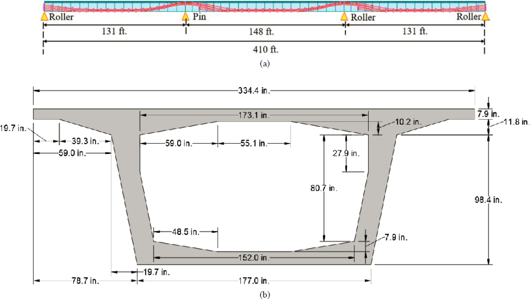
5.2 Example 1: Concrete Segmental Bridge Constructed with the Span-by-Span Method
The purpose of this example is to demonstrate the process of load rating a concrete segmental bridge constructed with the span-by-span method. The elevation and cross section of the bridge is shown in Figure 5-1. The complete set of load rating examples is provided in Appendix C (Load Rating Examples) of the Guideline.
5.3 Example 2: Concrete Segmental Bridge Constructed with the Cast-in-Place Balanced Cantilever Method
The purpose of this example is to demonstrate the process of load rating a concrete segmental bridge constructed with the cast-in-place concrete balanced cantilever method. The elevation and cross section of the bridge is shown in Figure 5-2. The term FSM refers to the full staging method and means that the segments within the green rectangle are fully shored when erected. In addition, the phrase key segment refers to the closure segment. The complete set of load rating examples is provided in Appendix C of the Guideline.
5.4 Example 3: Concrete Segmental Bridge Constructed with the Incremental Launching Method
The purpose of this example is to demonstrate the process of load rating a concrete segmental bridge constructed with the incremental launching method. The elevation and cross section of the bridge is shown in Figure 5-3. The complete set of load rating examples is provided in Appendix C of the Guideline.
5.5 Example 4: Concrete Segmental Bridge Constructed with the Cable-Stayed Method
The purpose of this example is to demonstrate the process of load rating a concrete segmental bridge constructed with the cable-stayed method. The elevation and cross section of the bridge is shown in Figure 5-4. The complete load rating example is provided in the load rating example document.


