Bus Operator Barrier Design: Guidelines and Considerations (2024)
Chapter: 2 Approach to Bus Operator Barrier Designs

CHAPTER 2
Approach to Bus Operator Barrier Designs
The goal of TCRP Project C-25, “Bus Operator Barrier Design,” was to produce information for North American public transportation agencies, standards committees, and government and non-government policy-making organizations on designing, procuring, and installing bus operator barriers to prioritize the health and safety of essential operators and the public they serve. The approach was to survey the transit bus industry, collect reference materials on the designs of barriers and heavy low-floor transit buses, summarize the design criteria, and produce three concept barrier configurations that may mitigate the risks to transit bus operator safety and health. The risks to bus operator health and safety specified by the TCRP Project C-25 panel for this research effort were
- physical attack,
- spitting attack,
- air quality,
- temperature extremes,
- ADA accessibility,
- usability and ergonomics, and
- driving visibility.
Risks considered in bus operator barrier designs are also affected by costs to manufacture, install or integrate, and maintain. Therefore, relative cost and complexity were considered as categories in the identification of the three concept bus operator barrier designs that would be produced. A range of transit agency needs and priorities also have to be considered by stakeholders developing guidance and regulations. Transit agency personnel with roles as managers, technicians, and operators are likely to have different preferences for types of bus operator barrier configurations. Some may prefer a higher prioritization for customer service and engagement and therefore desire a lower profile barrier, while others may prefer more security or even complete separation of the bus operator workstation compartment.
Besides considering preferences among bus operator barrier designs, the approach to developing all three bus operator barrier designs accounts for federal transportation requirements and standards that help ensure minimum safety and accessibility for the public while affecting procurement and funding for bus purchases that depend on these standards. Passengers with ambulatory impairments require handholds and stanchions to assist with navigating entryways and aisles. Additionally, persons with disabilities who use mobility devices require adequate clearance through doorways and aisles.
Another important consideration when adding a barrier in the bus operator workstation is material strength and transparency. Standards and recommended practices exist to define the safety, durability, and transmittance of parts of the barrier that must be viewed during driving. Selection of the materials used in a barrier, especially barriers that remain in place during driving operations, needs to take these requirements into consideration.
Multiple design guidelines provide criteria that either directly or indirectly impact bus operator barrier designs. These are available from APTA, published from the European Bus System of the Future (EBSF), the International Organization for Standardization (ISO), and TCRP under TRB and the National Academies of Sciences.
The approach for TCRP Project C-25 includes combining these sources of information to develop three concept bus operator barrier design configurations that address risks for bus operators while being grounded in the standards and transit bus designs common today and those that hold promise for tomorrow. To meet the need to address future transit bus designs, the research team applied the novel solution provided by the Bus of the Future team that was awarded by the FTA to develop a bus operator workstation compartment that would meet bus driver health and safety needs. The compartment included a concept bus operator barrier that completely separates the bus operator workstation from the passenger area or the passenger front entryway (or both, depending on the bus model). The Bus of the Future team was led by the International Transportation Learning Center (ITLC) in partnership with RLS & Associates, the Amalgamated Transit Union, and STYL&TECH. The research team worked directly with RLS & Associates on this TCRP project.
Survey on Transit Bus Barriers
The purpose of the survey was to collect preferences and needs for bus operator barriers, identify the design boundaries for bus operator barrier configurations for retrofit on existing buses, and collect traditional and novel barrier designs recently used by transit agencies. VTTI conducted the survey with the assistance of the ITLC for recruitment. The information collected in the survey was intended to support the goals of the project to produce information for stakeholders of North American public transit bus operations. Representatives from North American transit agencies and unions were sought to complete the survey. Outreach was made through direct e-mails, transit industry newsletters, and during conferences.
Respondents completed the survey through an online method on QuestionPro. It was estimated that the survey would take approximately 20–25 minutes to complete. Before completing the survey, respondents were asked to review a study information sheet explaining the purpose and use of the survey, which, when completed, implied consent. The survey research protocol was approved by the Virginia Tech Institutional Review Board. Data collected in the survey included
- basic demographics related to the respondent’s job and work history;
- bus operator barrier use, purpose, and requirements;
- descriptions of bus operator barrier designs in use and operational features;
- barrier maintenance requirements;
- barrier costs;
- barrier effectiveness;
- implementation challenges;
- training;
- benefits and positive outcomes;
- return on investment;
- future design recommendations and suggestions; and
- option to e-mail images of bus operator barriers in use at the survey respondent’s agency.
Guidelines, Standards, and Previous Research
North American and global recommended practices, guidelines, and standards were considered in the information collected to find related criteria for bus operator barrier designs.
Guidelines
Criteria and guidelines that pertain to bus operator workstations and bus operator barriers were reviewed and collected from APTA (7), EBSF (8), ISO (9), and TCRP (10).
Standards
Minimum requirements for accessibility for persons with disabilities on transit buses are defined in 49 CFR Part 37, Transportation Services for Individuals with Disabilities (ADA), and Part 38, ADA Accessibility Specifications for Transportation Vehicles.
In recent years, especially since the COVID-19 pandemic, barriers of many types have been developed by and for transit agencies as they have sought to protect their bus operators from air quality risks or attack. That demand brought many ideas for bus operator barriers to the industry. Because these barriers interface with the bus operator near the workstation, the designs could be placed in locations that in the past were considered as glazing (e.g., glass windows) used during vehicle driving tasks. Therefore, developers of glazing materials and bus operator barriers sought to understand the impacts of related standards on glazing.
In 2020, a bus dealer requested an interpretation from the NHTSA regarding whether transparent material used in shielding on bus operator barriers needed to comply with Federal Motor Vehicle Safety Standard (FMVSS) No. 205 on glazing materials. In a letter dated June 4 of that year, the NHTSA stated that this “shield assembly, located immediately to the right of a driver, is an interior partition composed of motor vehicle glazing that must comply with FMVSS No. 205.” (11) The letter continued to discuss the applications of FMVSS No. 205 to motor vehicles before first purchase and to aftermarket glazing for use in motor vehicles. Additional details noted that the manufacturer that cuts the glazing is responsible for certifying the glazing, but the assembler of an aftermarket bus operator barrier, as the manufacturer, is responsible for ensuring that the product is free from safety-related defects. The letter further denoted that “any portion of the glazing [in the bus operator barrier] that the driver would see through in order to view windows requisite for driving visibility would also be considered requisite for driving visibility.” (11)
Therefore, glazing materials used in bus operator barriers must meet 49 CFR 571.205 FMVSS Standard No. 205 for glazing materials. This federal regulation references other standards and practices that, among other requirements, cover strength, safety, and transmittance of glazing; examples include SAE J3097/ANSI Z26.1-MAY2019, “Standard for Safety Glazing Materials for Glazing Motor Vehicles and Motor Vehicle Equipment Operating on Land Highways—Safety Standard,” and J673-JUL2021, “Automotive Safety Glazing Materials.”
Visibility through glass during inclement weather and under differential external or internal humidity and moisture levels is covered by a standard and recommended practices for defrosting/defogging: 49 CFR 571.103 FMVSS Standard No. 103, “Windshield Defrosting and Defogging Systems,” and SAE J381-JUN2020, “Windshield Defrosting Systems Test Procedure and Performance Requirements—Trucks, Buses, and Multipurpose Vehicles.”
These are a selection of standards collected and reviewed to understand how they affect the design and integration of bus operator barriers on transit buses. It is important that agencies consult with bus procurement guidelines and federal agencies to ensure all relevant standards are considered before purchase and installation.
Previous Research
VTTI researchers on the TCRP Project C-25 team completed a series of projects in recent years that investigated transit bus barriers and produced guidelines and recommendations
for implementing retrofit barriers in existing buses and new workstation designs, which were applied to this effort. These project reports include TCRP Report 185: Bus Operator Workstation Design for Improving Occupational Health and Safety (12); FTA Report 0219, Transit Bus Mirror Configuration Pilot Project: Final Report (13); and FTA Report 0224, FTA Standards Development Program: Transit Bus Operator Temporary Barrier to Reduce COVID-19 Exposure (14). VTTI applied knowledge and expertise gained during these highly relevant projects to the development of bus operator barrier designs.
TCRP Report 185: Bus Operator Workstation Design for Improving Occupational Health and Safety
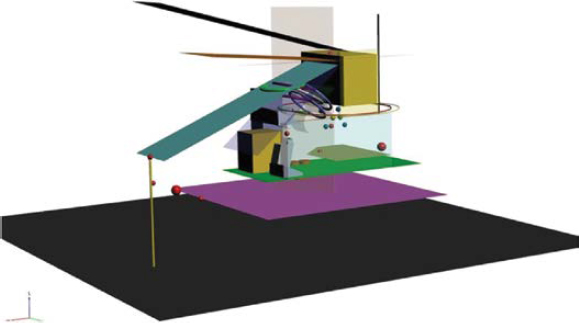
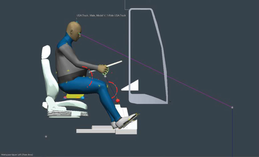
In TCRP Report 185, VTTI produced a global summary of bus operator workstation design requirements (see Table 1) and developed a universal file–formatted computer-aided design (CAD) model to serve transit agencies during procurement (Figure 1). The report demonstrated the design constraints present in current production transit buses in North America.
A bus operator workstation model was built as a simulation feasibility exercise to compare the guideline criteria with a transit bus in production in North America at that time (Figure 2). This project used TCRP Report 185 as background and again worked with a transit bus manufacturer to demonstrate the concept bus operator barrier designs inside a current production electric vehicle bus model.
Transit Bus Mirror Configuration Pilot Project: Final Report
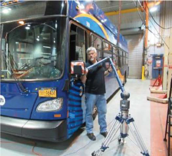
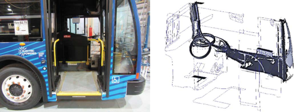
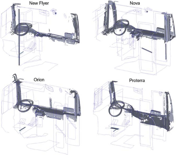
In this previous research, four transit buses were measured using a six-axis computer measurement machine and a laser light scanning device to produce 3-D CAD reverse-engineering transit bus operator workstation and visibility boundary models (Figure 3) at the New York
Table 1. Global bus operator workstation design guidelines compiled by VTTI for TCRP Report 185.
| Design Variables | TCRP Report 25 Guidelines | APTA Specification Guidelines | European Bus System of the Future | ISO 16121-1 through 4 | Updated for TCRP Report 25 | |
|---|---|---|---|---|---|---|
| Door Control | Location | N/A | Shall be located in the operator’s area within the hand reach envelope described in SAE Recommended Practice J287, “Driver Hand Control Reach.” Shall provide tactile feedback to indicate commanded door position and resist inadvertent door actuation. | N/A | N/A | Represented by 3-D CAD Models |
| Bus Floor | Height Above Ground | N/A | No more than 406 mm | N/A | N/A | No |
| Driver Platform | Height | N/A | Allows a seated bus operator to see a target positioned 610 mm in front of the bumper and 1067 mm above the ground. The height of the platform shall also allow the bus operator’s vertical upward view is less than 15°. | 300 (±50) mm above the bus floor and be reachable by a single step. If the platform height is greater than 350 mm, steps with equal height shall be provided with a maximum height of 250 mm and a minimum height of 125 mm. | Clear and unrestricted access to the bus operator’s workplace shall be ensured, with a passage width of at least 500 mm. | Yes |
NOTE: N/A = not applicable.
City Transit Department of Buses (NYCT DOB) maintenance facility. During this research, the VTTI team also measured and modeled the security barriers installed in each of the four transit bus configurations (Figure 4 and Figure 5). The research team applied information from these designs to identify typical components and design elements considered in the concept bus operator barrier designs.
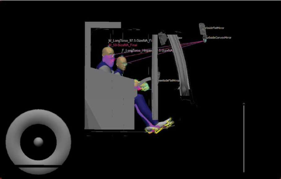
Using the 3-D bus operator workstation models, VTTI used human simulation tools to compare the bus visibility benchmarking performance comparisons of the four buses (Figure 6) and applied the performance measures to develop direct and mirror visibility guidance that led to
a novel mirror design for demonstration in New York City. VTTI applied the sight line and visibility performance data to guide development of the bus operator barrier designs.
FTA Standards Development Program: Transit Bus Operator Temporary Barrier to Reduce COVID-19 Exposure
During the COVID-19 pandemic, researchers at VTTI performed field testing with three transit bus HVAC configurations and evaluated their ventilation performance (Figure 7) during static and dynamic operation of three high-volume in-service transit buses in North America
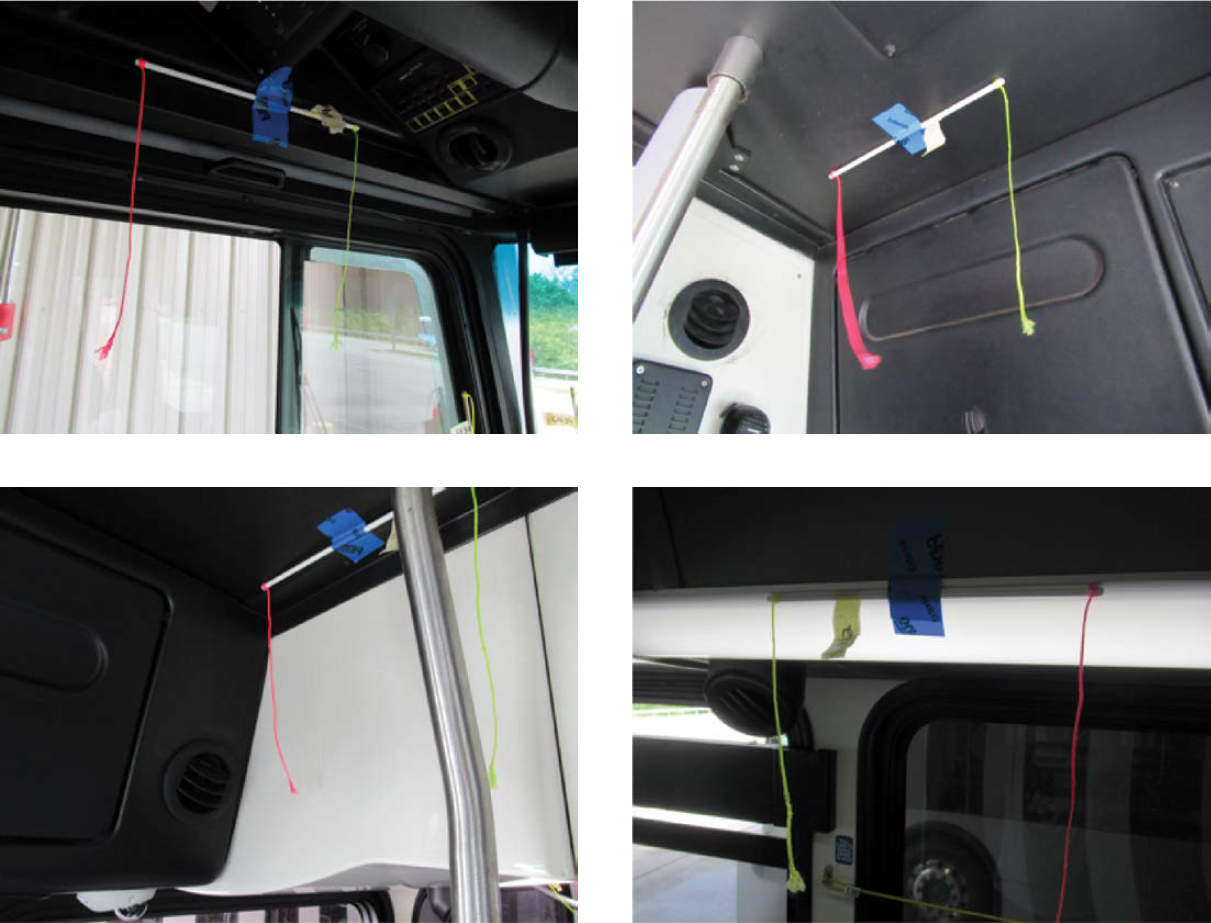
(e.g., rear/mid and rear HVAC intakes on New Flyer and Gillig models). VTTI cooperated with two local transit agencies in Blacksburg and Roanoke, Virginia, to apply barriers to buses for testing between service periods. A concept barrier designed by VTTI was tested to determine whether it could create a negative pressure zone at the front of the barrier, thereby reducing the open-air mixture between the bus operator workstation and the passenger area (Figure 8).
Testing revealed that temporary barriers were successful in buses equipped with rear-intake passenger HVAC configurations. The research team produced a technical brief and a 3-D CAD model of the temporary barrier that was made available for public download and implementation. This research led to FTA Report 0224, which offered recommendations to transit agencies on practical principles they could use to reduce exposure for bus operators and bus passengers (Figure 9 and Figure 10).
The findings of FTA Report 0224 illustrate the complex variables to be considered when developing guidelines for transit bus operator workstation security and health, and the design of barriers intended to support both. The addition of barriers can lead to changes in the airflow that may

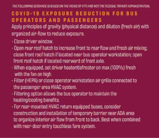

improve or degrade existing HVAC systems. Other performance, such as heating, cooling, and defrosting/defogging, can also be affected. That performance can affect the thermal comfort of the bus operator. Additional glazing and surfaces between the bus operator and side glass or onboard passengers may also affect the bus operator’s ability to see the roadway or to monitor and serve passengers. Bus operator barriers may require additional air treatment to manage different temperatures and humidity levels on each side of the barrier.
FTA Report 0224 also highlights the challenge of managing air quality on buses. For example, some barrier designs may reduce risks to bus operators of passengers sneezing on them, but viral risks have recently been recognized to extend beyond droplet contact. This research observed the influences of air pressure on the exterior of the bus while the bus is in motion, which will affect the air pressure and airflow inside the bus. Likewise, low-flow airflow zones inside the bus were observed when all exterior windows and hatches or defrosting ducts were closed. This effect on pressure varied by bus configuration. Some bus HVAC systems had little to no controlled fresh air intake, especially those that had rear-mounted HVAC units. Other buses with roof-mounted HVAC units always operated with 20% fresh air intake. Future designs of rear- and roof-mounted units may come with a combination of fresh air intake solutions. The primary takeaway was that it is important to select a solution that considers the complete vehicle and HVAC system and the differences between bus configurations when designing and implementing bus operator barriers.
Bus of the Future Redesign of Transit Bus Operator Compartment to Improve Safety, Operational Efficiency, and Passenger Accessibility Program
TCRP Project C-25, “Bus Operator Barrier Design,” was performed in collaboration with members of the team who worked on the Bus of the Future project. This project was funded by the FTA in 2020, and the research was performed by the ITLC to find ways to protect operators from assault and to improve their view of the road through innovative designs (15). The team was composed of experts from the Amalgamated Transit Union, STYL&TECH, AC Transit, RLS & Associates, and Vision Systems. The research objectives were to improve ineffective transit bus barriers, improve operator visibility, and create a separate operator workstation. The separate operator workstation was intended to maximize security, provide a sealed compartment that might be capable of positive air pressure on the operator side of the barriers, provide bus operator access through a pneumatically powered barrier door with glazing, and provide options to eliminate barrier reflections.
The team developed a bus operator workstation and concept bus operator barriers on a previously existing chassis not in production at this time. This bus chassis provided the team with the
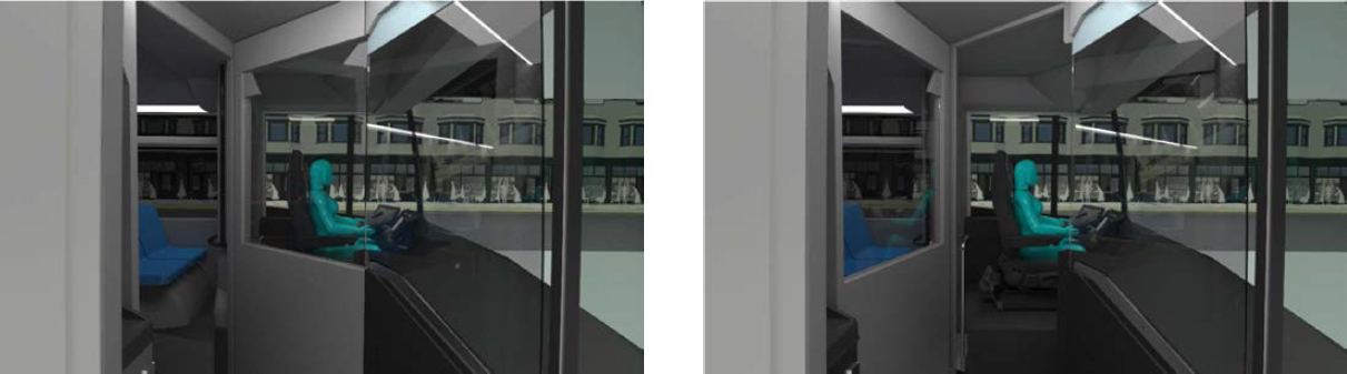
Figure 11. Concept Bus of the Future separate bus operator workstation with integrated door in the passenger entry mode position (left) and bus driving mode position (right).
opportunity to check the feasibility of the concept against an example transit bus configuration. The resulting workstation concept is demonstrated in Figure 11.
The security and separation of the air space was a priority for the design. The concept created a separate boundary at the typical standee line that allowed the bus operator workstation door to be opened and closed and securely sealed the front of the bus from either the entire passenger front entryway or the entire passenger compartment (Figure 12).
Another priority for the design was to prevent the bus operator barrier and door from creating new obstructions and furthermore to improve visibility for driving, passenger boarding and deboarding, and passenger service. To accomplish this, the two positions of the door were intended to allow the bus operator to drive the bus without any new surfaces between the operator and the windshield or the passenger front entry door, which is considered to support visibility for driving and boarding operations similar to the driver-side window on the street side of the bus. The additional static barriers added to the front of the bus were designed to avoid creating additional obstructions from the perspective of a bus operator looking at the curbside A-pillar, the vertical structure on the front side of the front passenger entry door (Figure 13). The bus
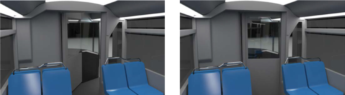
Figure 12. Concept Bus of the Future passenger compartment from the perspective of the bus operator workstation with the door in the passenger entry mode position (left) and bus driving mode position (right).
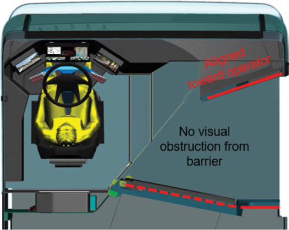
Figure 13. Concept Bus of the Future bus operator workstation compartment from top view demonstrating the bus operator barrier door in the driving mode position and angle of static barrier near the curbside A-pillar aligned with the viewing angle of the bus operator.
operator workstation design also included concept cameras and displays positioned to avoid obstructing forward visibility and to improve the size of objects and clarity of images usually viewed in the exterior side rearview mirrors (Figure 14).
The Bus of the Future team collaborated with the TCRP C-25 research team to provide information and design detail to support the illustration of one of the three concept bus operator barriers demonstrated in this project.
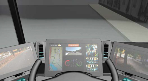
Figure 14. Concept Bus of the Future bus operator workstation with a view from the driver’s perspective looking down at the displays in front of the steering wheel, which show views through the rearview cameras that replace the exterior side mirrors.
Design Criteria
Design criteria were collected from the following sources: APTA, EBSF, ISO, and TCRP. The collection of criteria for designing bus operator barriers built on a previous exercise of criteria collection produced in TCRP Report 185 (16). One tool developed with this report was Design Tool 1, the International Transit Bus Operator Workstation Guideline Matrix. This design criteria matrix was collected from three non-TCRP sources (i.e., APTA, EBSF, and ISO) and TCRP Report 25: Bus Operator Workstation Evaluation and Design Guidelines (17) to produce a full list of bus operator workstation design variables. The collection of these criteria was applied in the selection of design variables that affect bus operator barriers. Criteria from other sources, such as military standard MIL-STD-1472G (18), SAE, Code of Federal Regulations Parts 37 and 38 (ADA), FMVSS, and some miscellaneous sources (e.g., NHTSA Letter of Interpretation on Driver Shield for Buses and Vans), were also included in the collection.
The design variables included in the bus operator barrier requirement matrix are organized by area or component and features of that component. All features are provided in Appendix A. The areas and components are listed as follows:
- Operator Workstation;
- Seat;
- Steering Wheel;
- Pedals;
- Farebox;
- Door Control (Passenger Entry);
- Bus Floor;
- Driver’s Area;
- Ventilation, Climate;
- Ventilation, Airflow;
- Driver Area Barrier;
- Modesty Panels;
- Driver-Side Window;
- Passenger Doors;
- ADA Wheelchair;
- General Safety;
- Side Windows;
- Bus Operator Barrier;
- Bus Operator Barrier, Door; and
- Mirror.
Feature design variables in the matrix are enumerated with each component design variable. For example, feature variables for the “Bus Operator Barrier” component variable are General; Panels; Materials, Strength; Materials, Fire Safety; Materials, Transparency; and Passenger Service, Fare. Each individual feature variable is classified according to the level of interface with a bus operator barrier design along one of multiple levels: primary, secondary, tertiary, clearance, and reference only. Examples of these levels and features are examined in this section.
A feature variable criterion that directly affects the design of a bus operator barrier is classified as “primary.” For example, the FMVSS criterion for the feature variable “Materials, Strength” under the variable “Bus Operator Barrier” states, “According to NHTSA, any transparent material to the right of a driver is an interior partition motor vehicle glazing that must comply with FMVSS No. 205, Glazing materials. FMVSS No. 205 requires by reference that the material comply with ANSI/SAE Z26.1-1996 fracture test.” Therefore, this criterion directly impacts the strength requirement of selected glazing used in the bus operator barrier design.
A feature variable criterion that has a second-degree indirect interface with the design of a bus operator barrier is classified as secondary. For example, the FMVSS criterion for feature variable “Controls and Temperature Uniformity” under the variable “Ventilation, Climate” states,
Per FMVSS No. 103, S4. Except as provided in paragraph (b) of this section [applicable to non-continental US bus manufacturing], each passenger car shall meet the requirements specified in S4.1, S4.2, and S4.3, and each multipurpose passenger vehicle, truck, and bus shall meet the requirements specified in S4.1. S4.1: Each vehicle shall have a windshield defrosting and defogging system. Criteria should be applied from SAE J381-JUN2020 Recommended Practice for defrosting performance of windshield target and defrosting performance of side window project mirror perimeter.
This criterion indirectly affects the bus operator barrier, as criteria for the HVAC defrosting and defogging performance of glazing on the bus operator barrier between the bus operator and windshield, curbside mirror, or passenger entry door glass could affect driving visibility.
A feature variable criterion that has a third-degree indirect interface with the design of the bus operator barrier is classified as tertiary. For example, the EBSF criterion for feature variable “Spacing” under the variable “Pedals” states, “Accelerator pedal: longitudinal spacing with bodywork (≥50 mm); lateral spacing with bodywork (≥30 mm).” This pedal positioning and spacing determines the position of the bus operator in the workstation. The bus operator barrier is intended to maximize coverage of the bus operator for security. Clearances around the bus operator’s feet and shoes on the pedals could affect dash panels and the size and position of the bus operator barrier relative to the bus operator workstation pedals and dash near the workstation. This area near the workstation often includes the farebox as well. The position and size of the farebox are related to these criteria for bus operator workstation clearance and closeout.
A feature variable criterion that has a clearance interface with the design of the bus operator barrier was classified as “clearance.” For example, the ISO 16121 criterion for the feature variable “Workplace Width” under the variable “Operator Workstation” states, “The bus operator compartment should allow for clearance to the operator’s shoulders and elbows (min. 800 mm cross-bus).” The bus operator needs to have sufficient clearance for their arms and elbows to move in the seat and adjust the steering wheel rotation while driving. Therefore, this clearance should be afforded in the bus operator barrier design. It is not a primary-level criterion because this criterion is not a property of the barrier itself, but this clearance remains important.
Some feature variable criteria did not have a direct, indirect, or clearance interface with the design of bus operator barriers. However, the criteria are informative as a “reference” to designers and implementers when developing a solution. For example, the APTA criterion for feature variable “Strength” under the variable “Modesty Panels” states, “The modesty panel and its mounting shall withstand a static force of 250 lbs applied to a 4 × 4-in. area in the center of the panel without permanent visible deformation.” This criterion may be useful as a security and strength test for surfaces that are neither glazed nor affected by FMVSS No. 205 criteria but that still need to withstand damage from intentional force directed at the bus operator.
Design for Risk Mitigation
The bus operator barrier designs were conceived on the basis of priorities requested by the TCRP panel, including assault prevention, air quality and ventilation, and thermal considerations; bus operator visibility, protection, security, safety, health, mobility, and comfort; ADA compliance for bus access and mobility; and emergency egress. Three concept bus operator barrier configurations were developed to mitigate these risks to bus operators while recognizing that transit agencies will seek a range of options based on cost, complexity, and prioritization of risks for new and existing buses. The first two concepts, A and B, were developed with a focus on existing bus production in North America. These two concepts were intended to
be capable of being integrated and manufactured in first-purchase production or aftermarket transit buses. However, the third concept, C, was based on the expectation that the bus operator workstation would be integrated with the entire bus body at first-purchase production in future buses.
The research team at VTTI applied the information collected from the TCRP panel, guidelines, standards, previous research, and the survey to develop a target risk mitigation approach for the three bus barrier concepts. The target assignment of risk mitigation to bus operator barrier design concept and relative cost and complexity is provided in Table 2.
Concept A Risk Mitigation Targets
- Type: Retrofit/integrated
- This concept was intended to be retrofit on existing buses or integrated into first-purchase buses. The barrier was composed primarily of one panel that also served as the door for the bus operator to access the bus operator workstation.
- Cost: Low
- The barrier was intended to be developed, manufactured, and installed at relatively low cost and complexity.
- Physical attack mitigation: Medium
- The barrier was made large enough to limit most physical attacks by passengers reaching toward the bus operator. This was assessed at a medium risk mitigation.
- Spitting attack mitigation: Low
- The barrier does not extend to the windshield and therefore will provide low risk mitigation for spitting attack, because passengers who intend to expectorate on the bus operator may be able to get around the barrier.
- Air quality mitigation: Low
- The barrier does not extend to the windshield and therefore will provide low risk mitigation for air quality, considering that air mixture and airflow will not be affected by the barrier.
- Temperature mitigation: Low
- The barrier does not extend to the windshield and therefore will provide low risk mitigation for temperature.
- ADA accessibility mitigation: High
- The barrier design was intended to avoid interference with (1) handholds for passengers who have ambulatory impairments and (2) the minimum ADA wheelchair access, thus targeting a high risk mitigation.
Table 2. Bus operator barrier design concepts, type, relative cost and complexity, and risk control mitigation.
| Concept/Type/Cost | Risk Controls | ||||||||
|---|---|---|---|---|---|---|---|---|---|
| Concept | Type | Cost | Physical | Spitting | Air | Temperature | ADA | Usability | Visibility |
| A | Retrofit/Integrated | Low | Medium | Low | Low | Low | High | Medium | Medium |
| B | Retrofit/Integrated | Moderate | High | Medium | Medium (pressure) | Medium | High | High | High |
| C | Integrated | High | High | High | High (filtration) | High | High (mid-door) | High | High |
- Usability mitigation: Medium
- The barrier is operated manually by the bus operator and does not need to be adjusted between passenger entry and driving mode positions, which leads to a medium usability risk mitigation target.
- Visibility mitigation: Medium
- Because the location of the barrier is fixed during the passenger boarding and driving modes of revenue operations, the glazing of the barrier must not extend into the line of sight for the range of all driver eyepoints when the bus operator looks at the curbside mirror. The glazing was intended to extend to a height that may be in the line of sight to the front entry door to limit physical attacks. Therefore, the concept targeted a medium visibility risk mitigation owing to the possibility of glare on the glazing when the bus operator looks at the passenger front entry door.
Concept B Risk Mitigation Targets
- Type: Retrofit/integrated
- This concept was intended to be retrofit on existing buses or integrated into first-purchase buses. The barrier was designed to be assembled with a door panel and additional panels to create closeouts between the passenger front entry door area and the front right wheel panel on the curbside of the bus.
- Cost: Moderate
- The barrier was intended to be developed, manufactured, and installed at relatively moderate cost. This will be achieved through automatic features that will be integrated with other bus controls. Furthermore, the additional closeout panels between the passenger front entryway and the passenger compartment may increase costs above the first concept barrier.
- Physical attack mitigation: High
- The barrier extends to the windshield but not to the interior roof of the bus and therefore was intended to provide high risk mitigation for physical attack.
- Spitting attack mitigation: Medium
- The barrier extends to the windshield but not to the interior roof of the bus and therefore was intended to provide medium risk mitigation for spitting attack.
- Air quality mitigation: Medium (air pressure capable)
- The closeouts between the passenger front entryway and the passenger compartment, along with the size of the barrier, were intended to minimize gaps to 1 in. This design was intended to provide a high-pressure zone on the front of the bus operator barrier when HVAC or defrosting fan controls and exterior bus openings are managed to enable this flow away from the bus operator. Therefore, a medium risk mitigation was targeted for air quality.
- Temperature mitigation: Medium
- The size of the barrier was intended to limit cold airflow from the passenger front entry door, but it was not intended to maintain a sealed and separate climate zone for heating and air conditioning temperature management around the workstation. Therefore, the concept targeted a medium risk mitigation for temperature.
- ADA accessibility mitigation: High
- The barrier design was intended to avoid interference with handholds for passengers who have ambulatory impairments and with the minimum ADA wheelchair access, thus targeting high risk mitigation.
- Usability mitigation: High
- The barrier door was intended to be pneumatically powered and to automatically move between passenger entry and driving mode positions with electromagnetic latching at each position, which leads to a high usability risk mitigation. This operation required additional complexity to tie the system to the passenger entry door setting. Additionally, a manual
- Visibility mitigation: High
- Because the position of the barrier automatically adjusts during the driving mode, the glazing of the barrier can extend into the line of sight for the range of driver eyepoints when the bus operator is looking at the curbside rearview mirror and front entry door. Thus, Concept B still targets a high visibility risk mitigation.
override was intended to be included to allow the bus operator to move the barrier door while the passenger entry door is closed during periods of customer service. An emergency egress latch was also necessary in case the bus is involved in a collision and the driver needs to physically release the door without shutting down power from inside the bus.
Concept C Risk Mitigation Targets
- Type: Integrated only
- This concept was intended to be developed and integrated into first-purchase buses on a new bus body and chassis. The concept was composed of a door panel with drop glass and additional stationary panels to seal and separate the workstation from the bus passenger front entryway or from the passenger compartment.
- Cost: High
- Because the barrier was intended to be developed as part of a new body and chassis design, the cost to develop, manufacture, and install was anticipated to be high.
- Physical attack mitigation: High
- Because the barrier completely separates the bus operator from the passenger front entryway and passenger compartment, this concept was intended to provide high risk mitigation for physical attack, unless the driver decides to leave the drop glass lowered.
- Spitting attack mitigation: High
- Because the barrier completely separates the bus operator from the passenger front entryway and passenger compartment, this concept was intended to provide high risk mitigation for spitting attack, unless the driver decides to leave the drop glass lowered. This sealed doorway may also target an additional risk mitigation, reducing stress on bus operators from verbal abuse or attack.
- Air quality mitigation: High
- This concept was intended to provide a high-pressure zone on the front of the bus operator barrier, at least when the bus operator workstation is closed. Therefore, a high risk mitigation was targeted for air quality.
- Temperature mitigation: High
- Because the design was intended to seal the airspace between the bus operator and the passenger front entryway or passenger compartment, separate climate zones were intended for heating and air conditioning. This could lead to a need to defrost and defog these additional glazing surfaces with HVAC ducts near the barrier door and glazing. These opportunities come with added complexity and cost to the bus HVAC and defrosting systems.
- ADA accessibility mitigation: High (mid or rear door)
- The barrier design was intended to convert the primary entry door to the mid or rear positions for all passengers or at least for persons with ambulatory or ADA accessibility challenges. With this conversion in mind and assuming the docking operations in the future could be modified to provide for ADA mid/rear door entry, the target for ADA risk mitigation was high. If these assumptions cannot be met, then other solutions for separating the bus operator workstation would need to be developed, or lower risk mitigation would need to be targeted in future production design exercises.
- Usability mitigation: High
- As with Concept B, the barrier was intended to be pneumatically powered and to automatically move between passenger entry and driving mode positions with electromagnetic
- Visibility mitigation: High
- This concept barrier door also includes a drop-glass feature, allowing the driver the choice to keep the glazing lowered during driving and customer service periods. According to the Bus of the Future team, the stationary barrier panels near the curbside entry area and A-pillar were designed to be in the line of sight of the existing A-pillar to avoid additional visibility obstructions beyond those present as part of the bus body structure. The bus operator workstation design also included rearview mirror cameras and integrated displays; therefore, this design targeted high visibility risk mitigation. If all these features could be executed and implemented well in final production, this bus operator workstation would be considered best in class for visibility.
latching at each position, which leads to a high usability risk mitigation. Production designs may include a separate door control feature such as the passenger entry door, allowing bus operators to leave the door in either position. This operation requires additional complexity to tie the system to the passenger entry door setting or develop a separate barrier door control. Additionally, a manual override was intended to be included to allow the bus operator to move the barrier door while the passenger entry door is closed during periods of customer service. An emergency egress latch was also necessary in case the bus is involved in a collision and the driver needs to physically release the door without shutting down power from inside the bus.


