Background and Resources for the Design and Construction of Bonded and Unbonded Post-Tensioned Concrete Bridge Elements (2025)
Chapter: Appendix C: Design Examples
APPENDIX C
Design Examples
The design examples in Appendix C follow the AASHTO LRFD Bridge Design Specifications (BDS), 9th Edition, 2020, with proposed modifications based on the results from NCHRP Project 12-118. Further details on these proposed modifications can be found in the “Proposed AASHTO Specification Changes” document, which can be downloaded from the NCHRP Project 12-118 webpage at https://apps.trb.org/cmsfeed/TRBNetProjectDisplay.asp?ProjectID=4569.
Design Example 1
Simple Span Spliced Bulb-T Bridge
This design example follows the AASHTO LRFD Bridge Design Specifications (BDS), 9th Edition, 2020, with proposed modifications based on results from the NCHRP Project 12-118. Modifications to the current AASHTO BDS equations, notation, and articles are shown in Bold and/or Underlined.
195'-0" Span from CL to CL of abutments
11 - 90" Bulb T Girders labeled GA to GK spaced at 5'-9" o/c with 8" CIP composite deck
3 - Bulb T Girder segments: 31'-3", 128'-0", 31'-3" w/ 2'-0" CIP splices between girder segments and 3'-0 ⅞" CIP PT anchor block diaphragm
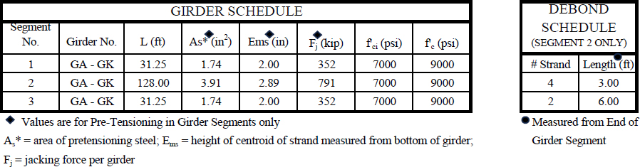
Precast Girder Concrete: f'ci = 7000 psi at release, f'c = 9000 psi at 28-days
CIP Splice Concrete: f'ci = 4500 psi at tendon stressing, f'c = 7250 psi at 28-days
CIP Deck Concrete: f'c = 4500 psi at 28-days
(4) 12-0.6" strand post-tensioning tendons stressed to 43.5 kip per strand (522 kip per tendon) with (2) tendons bonded and (2) tendons unbonded
Bulb-T Girder pre-tensioning per Girder Schedule below and shown in girder cross section details.
All pre-tensioning and post-tensioning strands are 0.6" diameter 270 ksi low relaxation
Shear reinforcement is (2) #4 stirrups in the girder web spaced at 6" at the girder ends.


Flexure Example
Calculate Moment Capacity at Midspan
| [LRFD Eq. 5.6.3.2.2-1 as modified by LRFD Art. 5.6.3.1.3b] | |
| [LRFD Eq. 5.6.3.1.1-1 as modified by LRFD Art. 5.6.3.1.3b] |
| [LRFD Eq. 5.6.3.1.2-1 as modified by LRFD Art. 5.6.3.1.3b] | |
| a = β1c | [LRFD Art. 5.6.2.2] |
| [LRFD Fig. C5.6.2.1-1] |
For T-section behavior:
| [LRFD Eq. 5.6.3.1.3b-1] |
For rectanglular section behavior:
| [LRFD Eq. 5.6.3.1.3b-2] |
Minimum Bonded Reinforcement:
| Abond_min = 0.004Act | [LRFD Art. 5.6.3.1.2] |
| Act = area of that part of cross section between the flexural tension face and centroid of gross section (in2) | [LRFD Art. 5.6.3.1.2] |
Section Design Information for Moment at Midspan:
| fpe = | 165.5 | ksi | Effective stress in prestressing steel after all instantaneous and time-dependent losses. Losses are calculated at the girder section per Art. 5.9.3.5. |
| fpu = | 270.0 | ksi | Specified ultimate tensile strength of prestressing steel |
| k = | 0.28 | Factor for low relaxation strand | |
| Apsb = | 9.114 | in2 | Area of bonded prestressted reinforcement, includes pre-tensioned and post-tensioned bonded strands |
| Apsu = | 5.208 | in2 | Area of unbonded prestressed reinforcement |
| dpb = | 93.48 | in | Depth to centroid of bonded prestressing from extreme comp. fiber |
| dpu = | 83.25 | in | Depth to centroid of unbonded prestressing from extreme comp. fiber |
| As = | 0.00 | in2 | Area of nonprestressed tension reinforcement |
| fy = | 60.00 | ksi | Specified minimum yield stress of As |
| ds = | 0.00 | in | Depth to centroid of As from extreme compressive fiber |
| A's = | 3.85 | in2 | Area of compression reinforcement (longitudinal deck reinforcement) |
| f'y = | 60.00 | ksi | Specified minimum yield stress of A's |
| d's = | 4.16 | in | Depth to centroid of A's from extreme compressive fiber |
| le = | 199.17 | ft | Effective tendon length between anchorages. Calculated as average tendon length. |
| f'c_girder = | 9.0 | ksi | Specified 28-day compressive strength of girder concrete |
| f'c_deck = | 4.5 | ksi | Specified 28-day compressive strength of deck concrete |
| β1_girder = | 0.65 | Stress block factor relative to neutral axis for girder concrete | |
| α1_girder = | 0.85 | Stress block factor for girder concrete | |
| β1_deck = | 0.825 | Stress block factor relative to neutral axis for deck concrete | |
| α1_deck = | 0.85 | Stress block factor for deck concrete | |
| b = | 69.00 | in | Composite deck width |
| bw = | 7.00 | in | Girder gross web width |
| hf = | 8.00 | in | Composite deck thickness |
| h = | 98.00 | in | Composite girder height |
| Mu = | 19960 | k-ft | Factored ultimate moment at section calculated per Strength I - V load combinations in LRFD Table 3.4.1-1 |
Calculate values for c, fpsu, and fpsb
Note: Iterative calculations shown for illustration. In practice, design programs and spreadsheets can be prepared with automated processes for this calculation.
Iteration #1
Assume initial value for c and iterate calcuations. Assume T-section behavior. Per Articles C5.6.2.2 and 5.6.3.2.6, utilize the lower concrete strength between the deck and girder for conservative results.
set c = 42.00 in
assume: f's = f'y
Calculate fpsb and fpsu, then check c.
| [LRFD Eq. 5.6.3.1.2-1 as modified by LRFD Art. 5.6.3.1.3b] | |
| [LRFD Eq. 5.6.3.1.1-1 as modified by LRFD Art. 5.6.3.1.3b] | |
| [LRFD Eq. 5.6.3.1.3b-1] |
Iteration #2
Calculate values for fpsu and fpsb using previous c value, then check c.
| fpsu = | 180.4 | ksi | [LRFD Eq. 5.6.3.1.2-1 as modified by LRFD Art. 5.6.3.1.3b] | |
| fpsb = | 234.6 | ksi | [LRFD Eq. 5.6.3.1.1-1 as modified by LRFD Art. 5.6.3.1.3b] | |
| c = | 43.00 | in | NG. Iterate Calculation. | [LRFD Eq. 5.6.3.1.3b-1] |
Iteration #3
Calculate values for fpsu and fpsb using previous c value, then check c.
| fpsu = | 180.7 | ksi | [LRFD Eq. 5.6.3.1.2-1 as modified by LRFD Art. 5.6.3.1.3b] | |
| fpsb = | 235.2 | ksi | [LRFD Eq. 5.6.3.1.1-1 as modified by LRFD Art. 5.6.3.1.3b] | |
| c = | 43.30 | in | Within 1%. OK | [LRFD Eq. 5.6.3.1.3b-1] |
Iteration #4
Calculate final values for fpsu and fpsb using accepted c value.
| fpsu = | 180.5 | ksi | Within 1%. OK | [LRFD Eq. 5.6.3.1.2-1 as modified by |
| LRFD Art. 5.6.3.1.3b] | ||||
| fpsb = | 235.0 | ksi | Within 1%. OK | [LRFD Eq. 5.6.3.1.1-1 as modified by LRFD Art. 5.6.3.1.3b] |
Check assumption: f's = f'y
| [LRFD Art. 5.6.2.1] |
Calculate "a", verify a > hf, and check that Tension equals Compression
| a = (0.825)(43.30)
a = 35.72 in | [LRFD Art. 5.6.2.2] |
is a > hf? Yes. T-section behavior confirmed.
T = (9.114)(235.0) + 5.208 180.5 + (0)(60)
T = 3082 kip
C = (0.85)(4.50)(69 − 7.0)(8.0) + (0.85) 4.50 (7.0)(35.72) + (3.85)(60)
C = 3085 kip
Check T = C T = C within 1%. OK
Calculate nominal moment capacity Mn.
| [LRFD Eq. 5.6.3.2.2-1 as modified by LRFD Art. 5.6.3.1.3b] |
Check if section is tension-controlled, compression controlled, or transition.
| εtl = | 0.005 | Tension controlled strain limit | [LRFD Art. 5.6.2.1] | |
| εcl = | 0.002 | Compression controlled strain limit | [LRFD Art. 5.6.2.1] | |
| dt = | 96.00 | in | Depth to extreme tension steel from the extreme compression fiber | [LRFD Fig. C5.6.2.1-1] |
| Transition Section | [LRFD Fig. C5.6.2.1-1] | |||
Calculate Moment Resistance Factor
| φcc = | 0.75 | Compression-controlled resistance factor | [LRFD Art. 5.5.4.2] |
| φtc = | 0.90 | Tension-controlled resistance factor for sections with unbonded tendons | [LRFD Art. 5.5.4.2] |
| Linear interpolation equation |
Check minimum bonded reinforcement criteria.
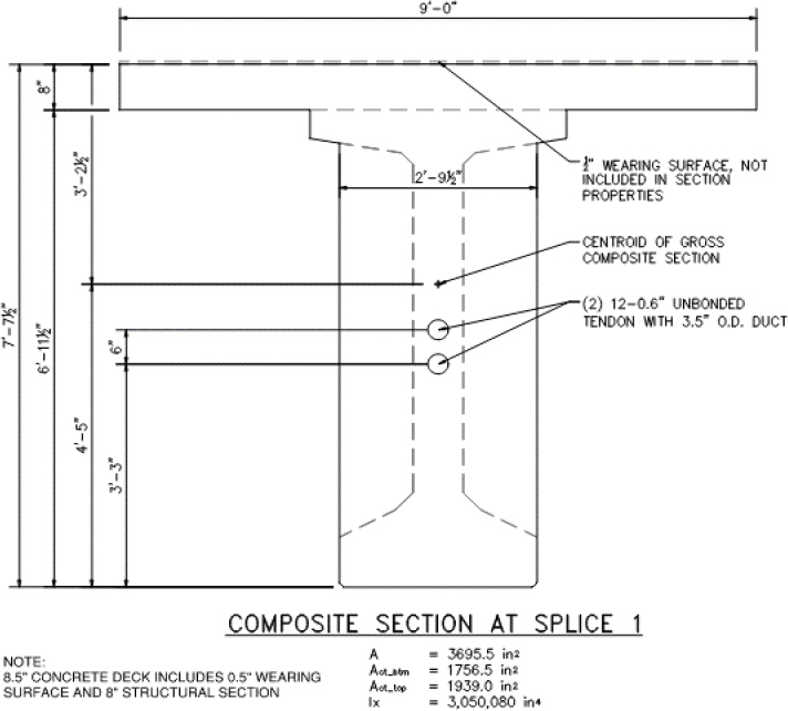
| Act = | 610.6 | in2 | From midspan composite section properties in Figure DE1-4 | [LRFD Art. 5.6.3.1.2] |
| Asb_min = Apsb = | 2.442 9.114 | in2 in2 | OK | [LRFD Art. 5.6.3.1.2] |
Check that φ Mn ≥ Mu
| φ Mn = | 17,540 | k-ft | |
| Mu = | 19,960 | k-ft | NG! |
Note that the calculated moment capacity does not include the contribution of the top flange of the precast girder in the compression block. Recalculate c and Mn while including the rectangular portion the girder top flange. Continue using f'c_deck for conservatism. Alternately, the designer may use strain compatibility for a more refined estimate of flexural capacity. See Article C5.6.2.2 for more information.
Only the final iteration is shown for illustrative purposes.
set c = 27.87 in
assume: f's = f'y
Calculate fpsb and fpsu, then check c.
| fpsu = | 186.4 | ksi | [LRFD Eq. 5.6.3.1.2-1 as modified by LRFD Art. 5.6.3.1.3b] |
| fpsb = | 247.5 | ksi | [LRFD Eq. 5.6.3.1.1-1 as modified by LRFD Art. 5.6.3.1.3b] |
| [LRFD Eq. 5.6.3.1.3b-1] |
Calculate final values for fpsu and fpsb using accepted c value.
| fpsu = | 186.4 | ksi | Within 1%. OK | [LRFD Eq. 5.6.3.1.2-1] |
| fpsb = | 247.5 | ksi | Within 1%. OK | [LRFD Eq. 5.6.3.1.1-1] |
Check assumption: f's = f'y
| 6.70 | > 3. OK | [LRFD Art. 5.6.2.1] |
Calculate "a", verify a > (hf + tf_girder), and check that Tension equals Compression
| a = | 23.00 | in | [LRFD Art. 5.6.2.2] |
is a > hf + 3.5 in? Yes. T-section behavior confirmed.
T = (9.114)(247.5) + 5.208 186.4 + (0)(60)
T = 3226 kip
C = (0.85)(4.50)(69 − 7.0)(8.0) + (0.85)(4.50)(43.0 − 7.0)(3.5) + (0.85)(4.50)(7.0)(23.00) + (3.85)(60)
C = 3226 kip T = C within 1%. OK
Calculate nominal moment capacity Mn.
| [LRFD Eq. 5.6.3.2.2-1 as modified by LRFD Article 5.6.3.1.3b] |
Check if section is tension-controlled, compression controlled, or transition.
| εtl = | 0.005 | Tension controlled strain limit | [LRFD Art. 5.6.2.1] | |
| εcl = | 0.002 | Compression controlled strain limit | [LRFD Art. 5.6.2.1] | |
| dt = | 96.00 | in | ||
| εt = | 0.0073 | Tension-Controlled Section | [LRFD Fig. C5.6.2.1-1] |
Calculate Moment Resistance Factor
| φcomp = | 0.75 | Compression-controlled resistance factor | [LRFD Art. 5.5.4.2] |
| φten = | 0.90 | Tension-controlled resistance factor for sections with unbonded tendons | [LRFD Art. 5.5.4.2] |
| φ = | 0.900 |
Check minimum bonded reinforcement criteria.
| Act = | 610.61 | in2 | From midspan composite section properties in Figure DE1-4 | [LRFD Art. 5.6.3.1.2] |
| Ab_min = | 2.44 | in2 | [LRFD Art. 5.6.3.1.2] | |
| Apsb = | 9.11 | in2 | OK |
Check that φ Mn ≥ Mu
| φ Mn = | 20,350 k-ft | |
| Mu = | 19,960 k-ft | OK |
Shear Example
Calculate Shear Capacity at Girder End Using Sectional Design Model
Vn equals the lesser of:
| Vn = Vc + Vs + Vp | [LRFD Eq. 5.7.3.3-1] |
| Vn = 0.25f'cbvdv + Vp | [LRFD Eq. 5.7.3.3-2] |
where:
| [LRFD Eq. 5.7.3.3-3] | |
| [LRFD Eq. 5.7.3.3-4] |
where for α = 90 degrees:
| [LRFD Eq. C5.7.3.3-1] | |
| [LRFD Eq. 5.7.3.4.2-1] | |
| [LRFD Eq. 5.7.3.4.2-3] | |
| [LRFD Eq. 5.7.3.4.2-4] |
Where:
| fpo = 0.7 fpu | appropriate for typical levels of prestressing | [LRFD Art. 5.7.3.4.2] |
| |Mu| shall not be less than: |Vu − Vp|dv | [LRFD Art. 5.7.3.4.2] | |
Minimum Transverse Reinforcement:
| [LRFD Eq. 5.7.2.5-1] |
Maximum Spacing of Transverse Reinforcement:
For vu < 0.125f'c:
| smax = 0.8dv ≤ 24.0 in | [LRFD Eq. 5.7.2.6-1] |
For vu ≥ 0.125f'c:
| smax = 0.4dv ≤ 12.0 in | [LRFD Eq. 5.7.2.6-2] |
Where:
| [LRFD Eq. 5.7.2.8-1] | |
| [LRFD Eq. C5.7.2.8-1 as modified by LRFD Art. C5.7.2.8] |
And:
| dv ≥ greater of: 0.9de or 0.72h | [LRFD Art. 5.7.2.8] |
in which:
| [LRFD Eq. 5.7.2.8-2 as modified by LRFD Art. C5.7.2.8] |
Section Design Information for Shear:
| fpe = | 170.2 | ksi | Effective stress in prestressing steel after all instantaneous and time-dependent losses calculated for this section per Art. 5.9.3.5. Note, there is less friction loss at this section relative to the midspan section used above. |
| fpu = | 270.0 | ksi | Specified ultimate tensile strength of prestressing steel |
| k = | 0.28 | Factor for low relaxation strand | |
| Apsb = | 6.944 | in2 | Area of bonded prestressted reinforcement |
| Apsu = | 5.208 | in2 | Area of unbonded prestressed reinforcement |
| dpb = | 87.98 | in | Depth to centroid of bonded prestressing from extreme comp. fiber |
| dpu = | 52.16 | in | Depth to centroid of unbonded prestressing from extreme comp. fiber |
| Av = | 0.40 | in2 | Transverse reinforcement = 2 - #4 stirrups in web |
| s = | 6.00 | in | Spacing of transverse reinforcement at section |
| α = | 90.00 | deg | Transverse reinforcement angle of inclination to longitudinal axis |
| As = | 0.00 | in2 | Area of nonprestressed reinforcement |
| fy = | 60.00 | ksi | Specified minimum yield stress of As |
| ds = | 0.00 | in | Depth to centroid of As from extreme comp. fiber |
| A's = | 3.85 | in2 | Area of compression reinforcement (longitudinal deck reinforcement) |
| f'y = | 60.00 | ksi | Specified minimum yield stress of A's |
| d's = | 4.16 | in | Depth to centroid of A's from extreme comp. fiber |
| Es = | 29000 | ksi | Modulus of elasticity of steel reinforcement |
| Ep = | 28500 | ksi | Modulus of elasticity of prestressing steel |
| le = | 199.25 | ft | Effective tendon length between anchorages |
| f'c_girder = | 9.00 | ksi | Specified 28-day compressive strength of girder concrete |
| f'c_deck = | 4.50 | ksi | Specified 28-day compressive strength of deck concrete |
| λgirder = | 1.00 | Concrete density modification factor for girder concrete | |
| λdeck = | 1.00 | Concrete density modification factor for deck concrete | |
| β1_girder = | 0.65 | Stress block factor relative to neutral axis for girder concrete | |
| α1_girder = | 0.85 | Stress block factor for girder concrete | |
| β1_deck = | 0.825 | Stress block factor relative to neutral axis for deck concrete | |
| α1_deck = | 0.85 | Stress block factor for deck concrete | |
| b = | 69.00 | in | Composite deck width |
| bw = | 7.00 | in | Girder gross web width |
| bv = | 3.50 | in | Girder effective web width reduced by duct diameter |
| dduct = | 3.50 | in | PT Duct outside diameter |
| hf = | 8.00 | in | Composite deck thickness |
| h = | 98.00 | in | Composite girder height |
| Vu = | 448.3 | kip | Factored ultimate verical shear at section calculated per Strength I - V load combinations in LRFD Table 3.4.1-1 |
| Vp = | 145.2 | kip | Vertical component of post-tensioning force at section |
| Mu = | 3070 | k-ft | Factored ultimate moment at section calculated per Strength I - V load combinations in LRFD Table 3.4.1-1 |
| Nu = | -1873.5 | kip | Factored axial force at section at section calculated per Strength I - V load combinations in LRFD Table 3.4.1-1 (negative indicates compression) |
Calculate values of Mn, fpsb, fpsu, and de needed for calculation of dv
Only final iteration shown for illustrative purposes.
Assume initial value for c and iterate calcuations. Assume T-section behavior.
Per Articles C5.6.2.2 and 5.6.3.2.6, utilize the lower concrete strength between the deck and girder for conservative results.
set c = 24.62 in
Calculate fpsb and fpsu, then check c.
| fpsu = | 180.6 | ksi | [LRFD Eq. 5.6.3.1.2-1] | |
| fpsb = | 248.8 | ksi | [LRFD Eq. 5.6.3.1.1-1] | |
| c = | 24.45 | in | Within 1%. OK | [LRFD Eq. 5.6.3.1.3b-1] |
Calculate final values for fpsu and fpsb using accepted c value.
| fpsu = | 180.6 | ksi | Within 1%. OK | [LRFD Eq. 5.6.3.1.2-1] |
| fpsb = | 249.0 | ksi | Within 1%. OK | [LRFD Eq. 5.6.3.1.1-1] |
Calculate nominal moment capacity Mn.
| a = | 20.17 | in | a > hf, T-section behavior confirmed. | [LRFD Art. 5.6.2.2] |
| Mn = | 185,810 | k-in = | 15,480 k-ft | [LRFD Eq. 5.6.3.2.2-1 as modified by LRFD Article 5.6.3.1.3b] |
Calculate value of de
| [LRFD Eq. 5.7.2.8-2 as modified by LRFD Art. C5.7.2.8] |
Calculate value of dv
| [LRFD Eq. C5.7.2.8-1 as modified by LRFD Art. C5.7.2.8] |
but not lesser than the greater of:
| 0.9de = (0.9)(75.36) = | 67.82 in | [LRFD Art. 5.7.2.8] |
| or | ||
| 0.72h = (0.72)(98) = | 70.56 in | [LRFD Art. 5.7.2.8] |
| dv = 70.56 in | Final value of dv |
Calculate values of β and θ needed for calculation of Vc and Vs.
| [LRFD Eq. 5.7.3.4.2-4] |
Check Mu ≥ |Vu-Vp|dv
|
|Vu − Vp|dv = |448.3 − 145.2|(70.56) =
= 21,387 k-in OK | [LRFD Art. 5.7.3.4.2] |
| [LRFD Eq. 5.7.3.4.2-1] | |
| θ = 29 + 3500(0)
θ = 29 | [LRFD Eq. 5.7.3.4.2-3] |
Calculate values of Vc and Vs.
| Vc = 112.4 kip | [LRFD Eq. 5.7.3.3-3] |
| Vs = 509.2 kip | [LRFD Eq. 5.7.3.3-4] | |
| φ = 0.85 | For shear in prestressed members having unbonded tendons. | [LRFD Art. 5.5.4.2] |
Check minimum transverse reinforcement and maximum transverse reinforcement spacing.
| Av_min = 0.07 in2 OK | [LRFD Eq. 5.7.2.5-1] |
| 0.125f'c = (0.125)(9.00) = 1.13 ksi | [LRFD Eq. 5.7.2.6-1] and [LRFD Eq. 5.7.2.6-2] |
| [LRFD Eq. 5.7.2.8-1] | |
| smax = 0.4(70.56) ≤ 12.0 in | |
| smax = 12.0 in > s, O.K. | [LRFD Eq. 5.7.2.6-2] |
Calculate factored shear resistance and check against ultimate shear load.
| Vn = 112.4 + 509.2 + 145.2 | |
| = 766.8 kip | [LRFD Eq. 5.7.3.3-1] |
but not greater than:
| Vn = 0.25(9.00)(3.50)(70.56) + 145.2 | |
| = 700.9 kip | [LRFD Eq. 5.7.3.3-2] |
| Vn = | 700.9 | kip | |
| φ Vn = | 595.7 | kip | |
| Vu = | 448.3 | kip | < φVn, OK |
Design Example 2
3-Span Continuous Spliced Bulb-T Bridge
This design example follows the AASHTO LRFD Bridge Design Specifications (BDS), 9th Edition, 2020, with proposed modifications based on results from the NCHRP Project 12-118. Modifications to the current AASHTO BDS equations, notation, and articles are shown in Bold and/or Underlined.
Span configuration: 123'-0" - 200'-0" - 126'-0" from CL to CL of piers along bridge CL.
Pier 3 and Pier 6 skew angle = 0.0°, Pier 4 and Pier 5 skew angle = 38.0°
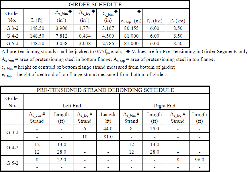
4 - 83.5" Bulb T Girder lines spaced at 9'-0" o/c with 8.5" CIP composite deck (8" structural and 0.5" sacrificial)
Each girder line has a different span configuration due to the skewed interior bents. Investigate Girder Line 2.
Girder Line 2 span configuration: 119'-5 ⅞" - 200'-0" - 129'-3 ⅛"
3 - Bulb T Girder segments: 148'-6", 148'-6", 148'-6" w/ 1'-6" CIP splices between girder segments and 3'-0" Precast PT anchor block and 3'-0" thickened web transition
Precast Girder Concrete: f'ci = 6.00 ksi at release, f'c = 8.50 ksi at 28-days
CIP Splice Concrete: f'ci = 4.50 ksi at tendon stressing, f'c = 6.00 ksi at 28-days
CIP Deck Concrete: f'c = 4.00 ksi at 28-days
(2) 12-0.6" strand undbonded post-tensioning tendons with 3.5" OD duct stressed to 0.75fpu (527.3 kip per tendon)
Bridge is erected with staged construction. Center span drop-in girder segment is supported from cantiliver overhang of the end girder segments using embedded steel erection corbels.
Bulb-T Girder pre-tensioning per Girder Schedule below and shown in girder cross section details.
All pre-tensioning and post-tensioning strands are 0.6" diameter 270 ksi low relaxation


Flexure Example
Check Positive and Negative Moment Capacity at Splice 1
| [LRFD Eq. 5.6.3.2.2-1 as modified by LRFD Art. 5.6.3.1.3b] | |
| [LRFD Eq. 5.6.3.1.1-1 as modified by LRFD Art. 5.6.3.1.3b] | |
| [LRFD Eq. 5.6.3.1.2-1 as modified by LRFD Art. 5.6.3.1.3b] | |
| [LRFD Art. 5.6.2.2] | |
| [LRFD Fig. C5.6.2.1-1] |
For T-section behavior:
| [LRFD Eq. 5.6.3.1.3b-1] |
For rectanglular section behavior:
| [LRFD Eq. 5.6.3.1.3b-2] |
Minimum Bonded Reinforcement:
| Abond_min = 0.004Act | [LRFD Art. 5.6.3.1.2] |
Act = area of that part of cross section between the flexural tension face and centroid of gross section (in2) | [LRFD Art. 5.6.3.1.2] |
Section Design Information for Moment:
| fpe = | 158.2 | ksi | Effective stress in prestressing steel after all instantaneous and time-dependent losses. Losses are calculated at the girder section per Art. 5.9.3.5. |
| fpu = | 270.0 | ksi | Specified ultimate tensile strength of prestressing steel |
| k = | 0.28 | Factor for low relaxation strand | |
| Apsb = | 0 | in2 | Area of bonded prestressed reinforcement |
| Apsu = | 5.208 | in2 | Area of unbonded prestressed reinforcement |
| dpb = | 0.00 | in | Depth to centroid of bonded prestressing from extreme comp. fiber |
| dpu_pos = | 49.50 | in | Depth to centroid of unbonded prestressing from extreme comp. fiber for positive moment |
| dpu_neg = | 42.00 | in | Depth to centroid of unbonded prestressing from extreme comp. fiber for negative moment |
| As = | varies | in2 | Area of nonprestressed tension reinforcement, equal to As_btm for positive moment and As_deck for negative moment |
| A's = | varies | in2 | Area of compression reinforcement, equal to As_deck for positive moment and As_btm for negative moment |
| As_deck = | 5.58 | in2 | Area of nonprestressed reinforcement in the composite deck (#5 spaced at 6" o/c) |
| fy_deck = | 60.00 | ksi | Specified minimum yield stress of As_deck |
| ds_deck = | 2.81 | in | Depth to centroid of As_deck from top of composite section |
| As_btm = | 2.64 | in2 | Area of nonprestressed reinforcement in the girder bottom flange (6-#6 centered at 4.5" above bottom of section) |
| fy_btm = | 60.00 | ksi | Specified minimum yield stress of As_btm |
| ds_btm = | 87.00 | in | Depth to centroid of As_btm from top of composite section |
| le = | 449.38 | ft | Effective tendon length between anchorages. Calculated as average tendon length. |
| f'c_splice = | 6.00 | ksi | Specified 28-day compressive strength of CIP splice concrete |
| f'c_deck = | 4.00 | ksi | Specified 28-day compressive strength of deck concrete |
| β1_splice = | 0.75 | Stress block factor relative to neutral axis for girder concrete | |
| α1_splice = | 0.85 | Stress block factor for girder concrete | |
| β1_deck = | 0.85 | Stress block factor relative to neutral axis for deck concrete | |
| α1_deck = | 0.85 | Stress block factor for deck concrete | |
| b = | 108.00 | in | Composite deck width |
| bw = | 33.50 | in | Girder gross web width at splice |
| hf = | 8.00 | in | Composite deck thickness |
| h = | 91.50 | in | Composite girder height |
| Mu_pos = | 367 | k-ft | Factored ultimate positive moment at section calculated per Strength I - V load |
| combinations in LRFD Table 3.4.1-1 | |||
| Mu_neg = | -3925 | k-ft | Factored ultimate negative moment at section calculated per Strength I - V load combinations in LRFD Table 3.4.1-1 |
Check Positive Moment Capacity
Calculate values for c and fpsu. Note that fpsb is not used because there is no bonded prestressed reinforcement at the CIP splice section.
Note: Iterative calculations shown for illustration. In practice, design programs and spreadsheets can be prepared with automated processes for this calculation.
Iteration #1
Assume initial value for c and iterate calcuations. Assume rectangular section behavior with compression in deck concrete.
set c = 4.00 in
As_deck = A's and As_btm = As
assume: fs = fy and f's = f'y
Calculate fpsu, then check c.
| [LRFD Eq. 5.6.3.1.2-1 as modified by LRFD Art. 5.6.3.1.3b] | |
| [LRFD Eq. 5.6.3.1.3b-1] |
Iteration #2
Calculate values for fpsu using previous c value, then check c.
| fpsu = | 166.1 | ksi | [LRFD Eq. 5.6.3.1.2-1 as modified by LRFD Art. 5.6.3.1.3b] | |
| c = | 2.21 | in | Within 1%. OK | [LRFD Eq. 5.6.3.1.3b-1] |
Iteration #3
Calculate final values for fpsu using accepted c value.
| fpsu = | 166.1 | ksi | Within 1%. OK | [LRFD Eq. 5.6.3.1.2-1 as modified by LRFD Art. 5.6.3.1.3b] |
Calculate "a", verify a < hf and a > d's
| a = (0.85)(2.18) | [LRFD Art. 5.6.2.2] | |
| a = 1.88 in | ||
| is a < hf? | Yes. Rectangular section behavior confirmed. | |
| is a > d's? | No. Compression steel located outside compression block. Recalculate c. |
Iteration #4 Recalculate c without compression steel.
set c = 3.26 in
As_btm = As
assume: fs = fy
Calculate fpsu, then check c.
| fpsu = | 165.9 | ksi | |
| c = | 3.28 | in | Within 1%. OK |
Check assumption: fs = fy
| [LRFD Art. 5.6.2.1] |
Calculate "a", verify a < hf, and check that Tension equals Compression
| a = | 2.78 | in | [LRFD Art. 5.6.2.2] | |
| is a < hf? | Yes. Rectangular section behavior confirmed. | |||
T = (5.208)(165.9) + (2.64)(60)
T = 1022 kip
C = (0.85)(4.0)(108)(2.78)
C = 1022 kip
Check T = C T = C within 1%. OK
Calculate nominal moment capacity Mn.
| [LRFD Eq. 5.6.3.2.2-1 as modified by LRFD Art. 5.6.3.1.3b] |
Mn = 55,130 k-in = 4,590 k-ft
Note: Per LRFD Art. 5.6.3.2.3, for rectangular sections bw shall be taken as b in LRFD Eq. 5.6.3.2.2-1
Check if section is tension-controlled, compression controlled, or transition.
| εtl = | 0.005 | Tension controlled strain limit | [LRFD Art. 5.6.2.1] | |
| εcl = | 0.002 | Compression controlled strain limit | [LRFD Art. 5.6.2.1] | |
| dt = | 89.00 | in | Depth to extreme tension steel from the extreme compression fiber | [LRFD Fig. C5.6.2.1-1] |
| Tension-Controlled Section | [LRFD Fig. C5.6.2.1-1] | |||
Calculate Moment Resistance Factor
| φcc = | 0.75 | Compression-controlled resistance factor | [LRFD Art. 5.5.4.2] | |
| φtc = | 0.90 | Tension-controlled resistance factor for sections with unbonded tendons | [LRFD Art. 5.5.4.2] | |
| φ = | 0.900 |
Check minimum bonded reinforcement criteria.
| Act = | 1756.5 | in2 | From midspan composite section properties in Figure DE2-4 | [LRFD Art. 5.6.3.1.2] |
| Asb_min = | 7.026 | in2 | [LRFD Art. 5.6.3.1.2] | |
| As_btm = | 2.64 | in2 | NG. Provide additional bonded reinforcement |
add 16 #5 bars centered at 3'-3" above bottom of girder section at splice
| Asb_prov = 2.64 + (16)(0.31) = | 7.60 in2 | OK |
Check that φ Mn ≥ Mu
| φ Mn = | 4,130 | k-ft | |
| Mu = | 367 | k-ft | OK |
Check Negative Moment Capacity
Calculate values for c and fpsu. Note that fpsb is not used because there is no bonded prestressed reinforcement at the CIP splice section.
Note: Iterative calculations shown for illustration. In practice, design programs and spreadsheets can be prepared with automated processes for this calculation.
Iteration #1
Assume initial value for c and iterate calcuations. Assume rectangular section behavior with compression in CIP splice concrete.
set c = 7.00 in
As_deck = As and As_btm = A's
assume: fs = fy and f's = f'y
Calculate fpsu, then check c.
| [LRFD Eq. 5.6.3.1.2-1 as modified by LRFD Art. 5.6.3.1.3b] | |
| [LRFD Eq. 5.6.3.1.3b-1] |
Iteration #2
Calculate values for fpsu using previous c value, then check c.
| fpsu = | 165.1 | ksi | [LRFD Eq. 5.6.3.1.2-1 as modified by LRFD Art. 5.6.3.1.3b] | |
| c = | 8.09 | in | Within 1%. OK | [LRFD Eq. 5.6.3.1.3b-1] |
Iteration #3
Calculate final values for fpsu using accepted c value.
| fpsu = | 165.1 | ksi | Within 1%. OK | [LRFD Eq. 5.6.3.1.2-1 as modified by LRFD Art. 5.6.3.1.3b] |
Calculate "a", verify a < precast girder depth and a > d's
| a = (0.75)(8.09) | [LRFD Art. 5.6.2.2] |
a = 6.07 in
| is a < precast depth? | Yes. Rectangular section behavior confirmed. |
| d's = h - ds_btm = 91.5 - 85.5 = | 4.50 in |
| is a > d's? Yes. Compression steel located in compression block | |
Check assumption: fs = fy
| [LRFD Art. 5.6.2.1] |
Check assumption: f's = f'y
The compression steel has not yielded. Per Article 5.6.2.1 the stress in the compression steel shall be determined using strain compatibility. Alternatively, the compression steel may be ignored. For this example, calculate the stress in the compression steel using strain compatibility.
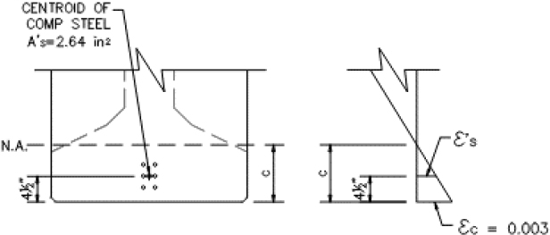 | |
| where: Es = 29,000 ksi |
Calculate values for c, f's, and fpsu. Note that fpsb is not used because there is no bonded prestressed reinforcement at the CIP splice section.
Note: Iterative calculations shown for illustration. In practice, design programs and spreadsheets can be prepared with automated processes for this calculation.
Iteration #1
Assume initial value for c and iterate calcuations. Assume rectangular section behavior with compression in CIP splice concrete. As_deck = As, As_btm = A's, and fs = fy
set c = 8.09 in
Calculate values for f's and fpsu, then check c.
| [LRFD Eq. 5.6.3.1.2-1 as modified by LRFD Art. 5.6.3.1.3b] | |
| [LRFD Eq. 5.6.3.1.3b-1] |
Iteration #2
Calculate values for f's and fpsu using previous c value, then check c.
| f's = | 40.82 | ksi | ||
| fpsu = | 165.0 | ksi | [LRFD Eq. 5.6.3.1.2-1 as modified by LRFD Art. 5.6.3.1.3b] | |
| c = | 8.48 | in | Within 1%. OK | [LRFD Eq. 5.6.3.1.3b-1] |
Iteration #3
Calculate final values for f's and fpsu using accepted c value.
| f's = | 40.83 | ksi | Within 1%. OK | |
| fpsu = | 165.0 | ksi | Within 1%. OK | [LRFD Eq. 5.6.3.1.2-1 as modified by LRFD Art. 5.6.3.1.3b] |
Calculate "a", verify a < precast girder depth and a > d's
| a = 0.75 8.48 a = 6.36 in | [LRFD Art. 5.6.2.2] |
| is a < precast depth? | Yes. Rectangular section behavior confirmed. | |
| d's = h - ds_btm = 91.5 - 87.0 = | 4.50 in | |
| is a > d's? | Yes. Compression steel located in compression block | |
Check assumption: fs = fy
| [LRFD Art. 5.6.2.1] |
T = (5.208)(165.0) + (5.58)(60)
T = 1194 kip
C = (0.85)(6.0)(33.50)(6.36) + (2.64)(40.83)
C = 1194 kip
| Check T = C | T = C within 1%. OK |
Calculate nominal moment capacity Mn.
| [LRFD Eq. 5.6.3.2.2-1 as modified by LRFD Art. 5.6.3.1.3b] |
Mn = -61,850 k-in = -5,150 k-ft
Note: Per LRFD Art. 5.6.3.2.3, for rectangular sections bw shall be taken as b in LRFD Eq. 5.6.3.2.2-1
Check if section is tension-controlled, compression controlled, or transition.
| εtl = | 0.005 | Tension controlled strain limit | [LRFD Art. 5.6.2.1] | |
| εcl = | 0.002 | Compression controlled strain limit | [LRFD Art. 5.6.2.1] | |
| dt = | 88.69 | in | Depth to extreme tension steel from the extreme compression fiber | [LRFD Fig. C5.6.2.1-1] |
| [LRFD Fig. C5.6.2.1-1] | ||||
| εt = | 0.0299 | Tension-Controlled Section | ||
Calculate Moment Resistance Factor
| φcc = | 0.75 | Compression-controlled resistance factor | [LRFD Art. 5.5.4.2] | |
| φtc = | 0.90 | Tension-controlled resistance factor for sections with unbonded tendons | [LRFD Art. 5.5.4.2] | |
| φ = | 0.900 |
Check minimum bonded reinforcement criteria.
| Act = | 1939.0 | in2 | From Splice 1 composite section properties in Figure DE2-4 | [LRFD Art. 5.6.3.1.2] |
| Asb_min = | 7.756 | in2 | [LRFD Art. 5.6.3.1.2] | |
| As_deck = | 5.58 | in2 | NG. Provide additional bonded reinforcement |
add 8 #5 bars centered at 6'-0" above bottom of girder section at splice
Asb_prov = 5.58 + (8)(0.31) = 8.06 in2 OK
Check that φ Mn ≥ Mu
| φ Mn = | -4,640 | k-ft | |
| Mu = | -3,925 | k-ft | OK |
Shear Example
Calculate Shear Capacity at Splice 1 for Positive and Negative moment envelopes
Vn equals the lesser of:
| Vn = Vc + Vs + Vp | [LRFD Eq. 5.7.3.3-1] |
| Vn = 0.25f'cbvdv + Vp | [LRFD Eq. 5.7.3.3-2] |
where:
| [LRFD Eq. 5.7.3.3-3] | |
| [LRFD Eq. 5.7.3.3-4] |
where for α = 90 degrees:
| [LRFD Eq. C5.7.3.3-1] | |
| [LRFD Eq. 5.7.3.4.2-1] | |
| [LRFD Eq. 5.7.3.4.2-3] | |
| [LRFD Eq. 5.7.3.4.2-4] |
Where:
| fpo = 0.7 fpu | appropriate for typical levels of prestressing | [LRFD Art. 5.7.3.4.2] |
| |Mu| shall not be less than: |Vu − Vp|dv | [LRFD Art. 5.7.3.4.2] | |
Minimum Transverse Reinforcement:
| [LRFD Eq. 5.7.2.5-1] |
Maximum Spacing of Transverse Reinforcement:
| [LRFD Eq. 5.7.2.6-1] | ||
| [LRFD Eq. 5.7.2.6-2] | ||
Where:
| [LRFD Eq. 5.7.2.8-1] |
| [LRFD Eq. C5.7.2.8-1 as modified by LRFD Art. C5.7.2.8] |
And:
| dv ≥ greater of: 0.9de or 0.72h | [LRFD Art. 5.7.2.8] |
in which:
| [LRFD Eq. 5.7.2.8-2 as modified by LRFD Art. C5.7.2.8] |
Section Design Information for Shear:
| fpe = | 158.2 | ksi | Effective stress in prestressing steel after all instantaneous and time-dependent losses calculated for this section per Art. 5.9.3.5. |
| fpu = | 270.0 | ksi | Specified ultimate tensile strength of prestressing steel |
| k = | 0.28 | Factor for low relaxation strand | |
| Apsb = | 0 | in2 | Area of bonded prestressed reinforcement |
| Apsu = | 5.208 | in2 | Area of unbonded prestressed reinforcement |
| dpb = | 0 | in | Depth to centroid of bonded prestressing from extreme comp. fiber |
| dpu_pos = | 49.5 | in | Depth to centroid of unbonded prestressing from extreme comp. fiber for positive moment |
| dpu_neg = | 42.00 | in | Depth to centroid of unbonded prestressing from extreme comp. fiber for negative moment |
| Av = | 0.80 | in2 | Transverse reinforcement = 4 - #4 stirrups in web |
| s = | 4.00 | in | Spacing of transverse reinforcement at section |
| α = | 90.00 | deg | Transverse reinforcement angle of inclination to longitudinal axis |
| As = | varies | in2 | Area of nonprestressed tension reinforcement, equl to As_btm for positive moment and As_deck for negative moment |
| A's = | varies | in2 | Area of compression reinforcement, equl to As_deck for positive moment and As_btm for negative moment |
| As_deck = | 5.58 | in2 | Area of nonprestressed reinforcement in the composite deck (#5 spaced at 6" o/c) |
| fy_deck = | 60.00 | ksi | Specified minimum yield stress of As_deck |
| ds_deck = | 2.81 | in | Depth to centroid of As_deck from top of composite section |
| As_btm = | 2.64 | in2 | Area of nonprestressed reinforcement in the girder bottom flange (8-#5 at 4" above bottom of section) |
| fy_btm = | 60.00 | ksi | Specified minimum yield stress of As_btm |
| ds_btm = | 87.00 | in | Depth to centroid of As_btm from top of composite section |
| Es = | 29000 | ksi | Modulus of elasticity of steel reinforcement |
| Ep = | 28500 | ksi | Modulus of elasticity of prestressing steel |
| le = | 449.38 | ft | Effective tendon length between anchorages |
| f'c_splice = | 6.00 | ksi | Specified 28-day compressive strength of CIP splice concrete |
| f'c_deck = | 4.00 | ksi | Specified 28-day compressive strength of deck concrete |
| λsplice = | 1.00 | Concrete density modification factor for girder concrete | |
| λdeck = | 1.00 | Concrete density modification factor for deck concrete | |
| β1_splice = | 0.75 | Stress block factor relative to neutral axis for girder concrete | |
| α1_splice = | 0.85 | Stress block factor for girder concrete |
| β1_deck = | 0.85 | Stress block factor relative to neutral axis for deck concrete | |
| α1_deck = | 0.85 | Stress block factor for deck concrete | |
| b = | 108.00 | in | Composite deck width |
| bw = | 33.50 | in | Girder gross web width |
| bv = | 30.00 | in | Girder effective web width reduced by duct diameter |
| dduct = | 3.50 | in | PT Duct outside diameter |
| hf = | 8.00 | in | Composite deck thickness |
| h = | 91.50 | in | Composite girder height |
| Vu_pos = | 225.7 | kip | Factored ultimate verical shear at section in positive moment envelope calculated per Strength I - V load combinations in LRFD Table 3.4.1-1 |
| Vu_neg = | 462.6 | kip | Factored ultimate verical shear at section in negative moment envelope calculated per Strength I - V load combinations in LRFD Table 3.4.1-1 |
| Vp = | 84 | kip | Vertical component of post-tensioning force at section taken as positive if resisting the applied shear |
| Mu_pos = | 367 | k-ft | Factored ultimate positive moment at section calculated per Strength I - V load combinations in LRFD Table 3.4.1-1 |
| Mu_neg = | -3925 | k-ft | Factored ultimate negative moment at section calculated per Strength I - V load combinations in LRFD Table 3.4.1-1 |
| Nu = | -699.3 | kip | Factored axial force at section calculated per Strength I - V load combinations in LRFD Table 3.4.1-1 (negative indicates compression) |
Check Shear for Positive moment envelope
From the moment calcuations above the values of Mn and fpsu for positive moment are shown below.
Note that fpsb is not used because there is no bonded prestressed reinforcement at the CIP splice.
| fpsu = | 165.9 | ksi | [LRFD Eq. 5.6.3.1.2-1 as modified by LRFD Art. 5.6.3.1.3b] | |
| Mn = | 55,130 | k-in = | 4,590 k-ft | [LRFD Eq. 5.6.3.2.2-1 as modified by LRFD Article 5.6.3.1.3b] |
Calculate de and dv
| [LRFD Eq. 5.7.2.8-2 as modified by LRFD Art. C5.7.2.8] |
Calculate value of dv
| [LRFD Eq. C5.7.2.8-1 as modified by LRFD Art. C5.7.2.8] |
but not lesser than the greater of:
| 0.9de = (0.9)(55.31) = | 48.53 in | [LRFD Art. 5.7.2.8] |
| or | ||
| 0.72h = (0.72)(91.50) = | 65.88 in | [LRFD Art. 5.7.2.8] |
| dv = | 65.88 | in | Final value of dv |
Check Mu ≥ |Vu-Vp|dv for positive and negative moment
| |Vu − Vp|dv = |225.7 − 84.0|(65.88) = = 9,335 k-in >Mu, use this value | [LRFD Art. 5.7.3.4.2] |
Calculate values of β and θ needed for calculation of Vc and Vs.
| [LRFD Eq. 5.7.3.4.2-4] | |
| [LRFD Eq. 5.7.3.4.2-1] | |
| θ = 29 + 3500(0) θ = 29 | [LRFD Eq. 5.7.3.4.2-3] |
Calculate values of Vc and Vs.
| [LRFD Eq. 5.7.3.3-3] | |
| [LRFD Eq. 5.7.3.3-4] |
| φ = | 0.85 | For shear in prestressed members having unbonded tendons. | [LRFD Art. 5.5.4.2] |
Check minimum transverse reinforcement and maximum transverse reinforcement spacing.
| [LRFD Eq. 5.7.2.5-1] | |
| 0.125f'c = (0.125)(6.00) = 0.75 ksi | [LRFD Eq. 5.7.2.6-1] and [LRFD Eq. 5.7.2.6-2] |
| [LRFD Eq. 5.7.2.8-1] | |
| smax = 0.8(65.88) ≤ 24.0 in smax = 24.0 in > s, O.K. | [LRFD Eq. 5.7.2.6-2] |
Calculate factored shear resistance and check against ultimate shear load.
| Vn = 820.0 + 1426.2 + 84.0 = 2330.2 kip | [LRFD Eq. 5.7.3.3-1] |
but not greater than:
| Vn = 0.25(6.00)(30.0)(65.88) +84.0 = 3048.6 kip Vn = 2330.2 kip | [LRFD Eq. 5.7.3.3-2] |
| φ Vn = 1980.7 kip |
| Vu = 225.7 kip < φVn, OK |
Check Shear for Negative moment envelope
From moment calcuations above the values of Mn and fpsu for negative moment are shown below.
Note that fpsb is not used because there is no bonded prestressed reinforcement at the CIP splice.
| fpsu = | 165.0 | ksi | [LRFD Eq. 5.6.3.1.2-1 as modified by LRFD Art. 5.6.3.1.3b] | |
| Mn = | -61,850 | k-in = | -5,150 k-ft | [LRFD Eq. 5.6.3.2.2-1 as modified by LRFD Article 5.6.3.1.3b] |
Calculate de and dv
| [LRFD Eq. 5.7.2.8-2 as modified by LRFD Art. C5.7.2.8] |
Calculate value of dv
| [LRFD Eq. C5.7.2.8-1 as modified by LRFD Art. C5.7.2.8] |
but not lesser than the greater of:
| 0.9de = (0.9)(36.42) = | 32.77 in | [LRFD Art. 5.7.2.8] |
| or | ||
| 0.72h = (0.72)(91.50) = | 65.88 in | [LRFD Art. 5.7.2.8] |
| dv = | 65.88 | in | Final value of dv |
Check Mu ≥ |Vu-Vp|dv for positive and negative moment
| |Vu − Vp|dv = |462.6 − 84.0|(65.88) = = 24,942 k-in use Mu | [LRFD Art. 5.7.3.4.2] |
Calculate values of β and θ needed for calculation of Vc and Vs.
| εs = -0.00154 | Negative value. Use 0. | [LRFD Eq. 5.7.3.4.2-4] |
| [LRFD Eq. 5.7.3.4.2-1] | ||
| θ = 29 + 3500(0) θ = 29 | [LRFD Eq. 5.7.3.4.2-3] |
Calculate values of Vc and Vs.
| [LRFD Eq. 5.7.3.3-3] | ||
| [LRFD Eq. 5.7.3.3-4] | ||
| φ = 0.85 | For shear in prestressed members having unbonded tendons. | [LRFD Art. 5.5.4.2] |
Check minimum transverse reinforcement and maximum transverse reinforcement spacing.
| [LRFD Eq. 5.7.2.5-1] |
| 0.125f'c = (0.125)(6.00) = | 0.75 | ksi | [LRFD Eq. 5.7.2.6-1] and [LRFD Eq. 5.7.2.6-2] |
| [LRFD Eq. 5.7.2.8-1] | |
| smax = 0.8(65.88) ≤ 24.0 in smax = 24.0 in > s, O.K. | [LRFD Eq. 5.7.2.6-2] |
Calculate factored shear resistance and check against ultimate shear load.
| Vn = 820.0 + 1426.2 + 84.0 = 2330.2 kip | [LRFD Eq. 5.7.3.3-1] |
but not greater than:
| Vn = 0.25(6.00)(30.0)(65.88) +84.0 = 3048.6 kip Vn = 2330.2 kip | [LRFD Eq. 5.7.3.3-2] |
| φ Vn = 1980.7 kip |
| Vu = 225.7 kip < φVn, OK |
Design Example 3
3-Span Balanced Cantilever Precast Segmental Box Bridge
This design example follows the AASHTO LRFD Bridge Design Specifications (BDS), 9th Edition, 2020, with proposed modifications based on results from the NCHRP Project 12-118. Modifications to the current AASHTO BDS equations, notation, and articles are shown in Bold and/or Underlined.
Span configuration: 180'-0" - 312'-0" - 180'-0" from CL to CL of piers along bridge CL.
Variable depth double cell box girder erected using balanced cantilever method.
Precast Segment Concrete: f'ci = 4.50 ksi at release, f'c =6.50 ksi at 28-days
CIP Splice Concrete: f'ci = 4.00 ksi at tendon stressing, f'c = 6.00 ksi at 28-days
Cantilever Tendons: Tendons A - T: 11-0.6" strand PT tendons with 3.5" OD duct stressed to 0.78fpu (502.7 kip per tendon). Tendon U: 5-0.6" strand PT tendons with 2.5" OD duct stressed to 0.78fpu (228.5 kip per tendon). Cantilever tendons A to J are considered to be bonded at the completion of segment erection. Cantilever tendons K to T are considered unbonded at the completion of segment erection. All cantilever tendons are bonded for final service conditions. Refer to the most current version of PT M55.1 Specification for Grouting of Post-Tensioned Structures for time limits between stressing and grouting of tendons.
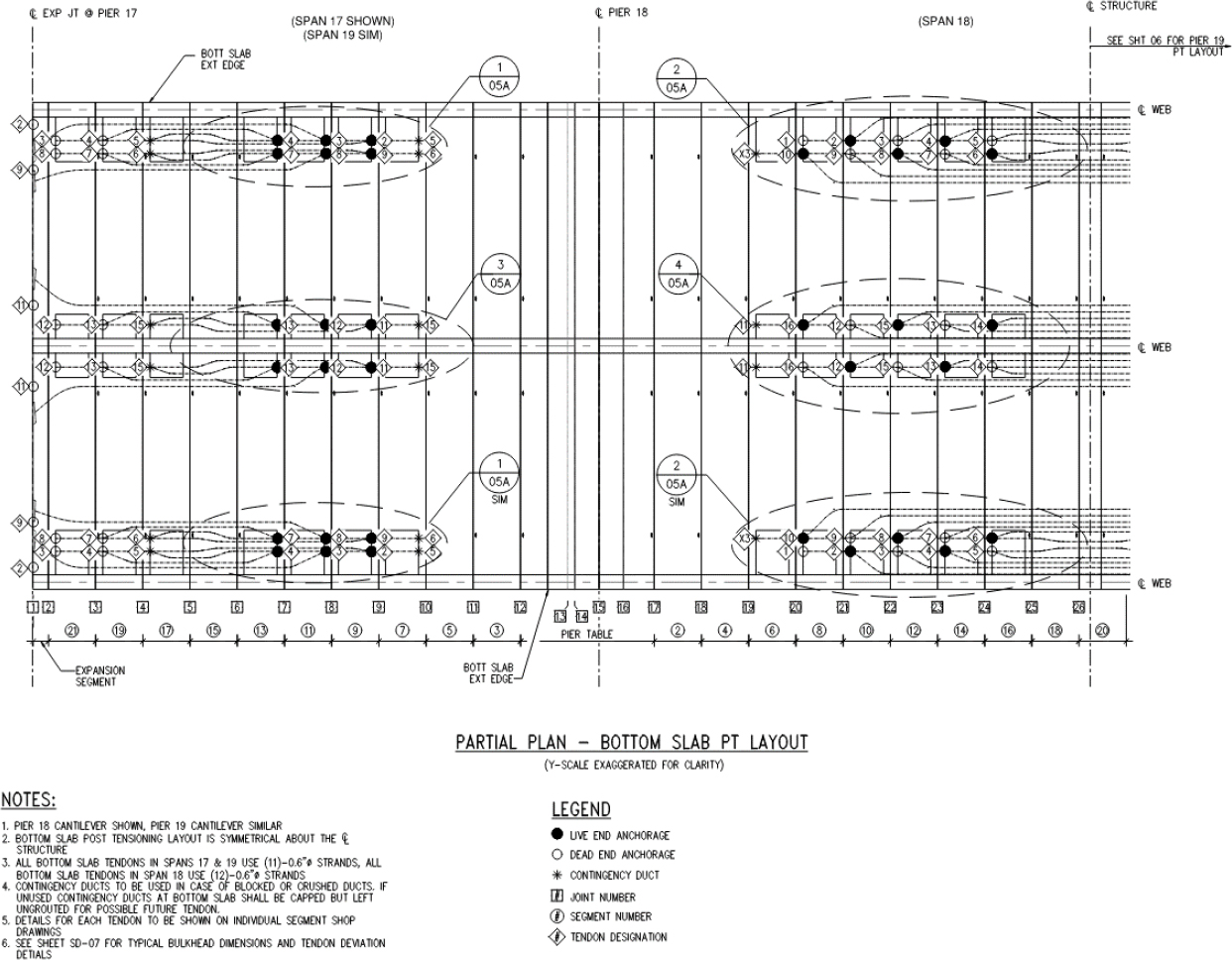
Bottom Slab Tendons: Spans 17 and 19, Tendons 2-4, 7-9, 11-13: 11-0.6" strand PT tendons with 3.5" OD duct stressed to 0.78fpu (502.7 kip per tendon).
Span 18, Tendons 1-10, 12-16: 12-0.6" strand PT tendons with 3.5" OD duct stressed to 0.78fpu (548.4 kip per tendon). All bottom slab tendons are bonded for final service conditions.
Draped Tendons: (4) 19-0.6" strand external PT tendons stressed to 0.78fpu (868.3 kip per tendon). All draped tendons are external and unbonded for final service conditions.
All post-tensioning strands are 0.6" diameter 270 ksi low relaxation


Flexure Example
Negative Moment at Joint 16 during construction and in final service
Note: At this stage all precast segments have been erected, but the closure segment has not been cast. For the purposes of this example, at this stage of construction: cantilever tendons A to J are considered to be bonded, cantilever tendons K to T are considered to be unbonded, draped tendons are installed, and Tendon U is not installed. Note that Tendon A is anchored at joint 16, and therefore is not considered to be active across the joint. Refer to the most current version of PT M55.1 Specification for Grouting of Post-Tensioned Structures for time limits between stressing and grouting of tendons.
| [LRFD Eq. 5.6.3.2.2-1 as modified by LRFD Art. 5.6.3.1.3b] | |
| [LRFD Eq. 5.6.3.1.1-1 as modified by LRFD Art. 5.6.3.1.3b] | |
| [LRFD Eq. 5.6.3.1.2-1 as modified by LRFD Art. 5.6.3.1.3b] | |
| [LRFD Art. 5.6.2.2] | |
| [LRFD Fig. C5.6.2.1-1] |
For T-section behavior:
| [LRFD Eq. 5.6.3.1.3b-1] |
For rectanglular section behavior:
| [LRFD Eq. 5.6.3.1.3b-2] |
Minimum Bonded Reinforcement:
| Abond_min = 0.004Act | [LRFD Art. 5.6.3.1.2] |
Act = area of that part of cross section between the flexural tension face and centroid of gross section (in2) | [LRFD Art. 5.6.3.1.2] |
Section Design Information for Moment:
| fpe_con = | 179.4 | ksi | Effective stress in prestressing steel after all instantaneous and time-dependent losses during construction. Losses are calculated at section per Art. 5.9.3.5. |
| fpe_fin = | 164.3 | ksi | Effective stress in prestressing steel after all instantaneous and time-dependent losses in final service. Losses are calculated at section per Art. 5.9.3.5. |
| fpu = | 270.0 | ksi | Specified ultimate tensile strength of prestressing steel |
| k = | 0.28 | Factor for low relaxation strand | |
| Apsb_con = | 64.449 | in2 | Area of bonded prestressed negative moment reinforcement during construction |
| Apsb_fin = | 138.229 | in2 | Area of bonded prestressed negative moment reinforcement in final service condition |
| Apsu_con = | 88.102 | in2 | Area of unbonded prestressed negative moment reinforcement during construction |
| Apsu_fin = | 16.492 | in2 | Area of unbonded prestressed negative moment reinforcement in final service condition |
| dpb_con = | 206.11 | in | Depth to centroid of bonded negative moment prestressing from extreme compression fiber during construction |
| dpb_fin = | 207.26 | in | Depth to centroid of bonded negative moment prestressing from extreme compression fiber in final service condition |
| dpu_con = | 204.23 | in | Depth to centroid of unbonded negative moment prestressing from extreme compression fiber during construction |
| dpu_fin = | 187.00 | in | Depth to centroid of unbonded negative moment prestressing from extreme compression fiber in final service condition |
| As = | 0.00 | in2 | Area of nonprestressed tension reinforcement |
| fy = | 60.00 | ksi | Specified minimum yield stress of As |
| ds = | 0.00 | in | Depth to centroid of As_deck from top of section |
| A's = | 0.00 | in2 | Area of compression reinforcement |
| f'y = | 60.00 | ksi | Specified minimum yield stress of A's |
| d's = | 0.00 | in | Depth to centroid of A's from top of section |
| le_con = | 230.54 | ft | Effective tendon length between anchorages. Use average tendon length for unbonded tendons during construction stage considered. |
| le_fin = | 193.10 | ft | Effective tendon length between anchorages. Use average tendon length for unbonded tendons at final service. |
| f'c = | 6.50 | ksi | Specified 28-day compressive strength of segment concrete |
| β1 = | 0.725 | Stress block factor relative to neutral axis for girder concrete | |
| α1 = | 0.85 | Stress block factor for segement concrete | |
| b = | 600.00 | in | Width of segment bottom slab |
| bw = | 54.00 | in | Segment gross web width |
| hf = | 18.00 | in | Thickness segment bottom slab |
| h = | 217.00 | in | Segment structural section depth |
| Mu_con = | -31,935 | k-ft | Factored ultimate negative moment during construction at section calculated per Strength I - V load combinations in LRFD Table 3.4.1-1 |
| Mu_fin = | -349,425 | k-ft | Factored ultimate negative moment in final service at section calculated per Strength I - V load combinations in LRFD Table 3.4.1-1 |
Check Negative Moment Capacity During Construction
Calculate values for c, fpsu, and fpsb.
Note: Iterative calculations shown for illustration. In practice, design programs and spreadsheets can be prepared with automated processes for this calculation.
Iteration #1
Assume initial value for c and iterate calcuations. Assume rectangular section behavior with compression in the segment bottom slab.
set c = 18.00 in
Calculate fpsu, then check c.
| [LRFD Eq. 5.6.3.1.2-1 as modified by LRFD Art. 5.6.3.1.3b] | |
| [LRFD Eq. 5.6.3.1.1-1 as modified by LRFD Art. 5.6.3.1.3b] |
| [LRFD Eq. 5.6.3.1.3b-1] |
Iteration #2
Calculate values for fpsu using previous c value, then check c.
| fpsu = | 240.7 | ksi | [LRFD Eq. 5.6.3.1.2-1 as modified by LRFD Art. 5.6.3.1.3b] | |
| fpsb = | 264.2 | ksi | [LRFD Eq. 5.6.3.1.1-1 as modified by LRFD Art. 5.6.3.1.3b] | |
| c = | 15.91 | in | Within 1%. OK | [LRFD Eq. 5.6.3.1.3b-1] |
Iteration #3
Calculate final values for fpsu using accepted c value.
| fpsu = | 240.7 | ksi | Within 1%. OK | [LRFD Eq. 5.6.3.1.2-1 as modified by |
| fpsb = | 264.2 | ksi | Within 1%. OK | LRFD Art. 5.6.3.1.3b] |
Calculate "a", verify a < precast girder depth and a > d's
| a = (0.725)(15.91) a = 11.53 in | [LRFD Art. 5.6.2.2] |
| is a < bottom slab depth? | Yes. Rectangular section behavior confirmed. |
T = (88.102)(240.7) + (64.449)(264.2)
T = 38228 kip
C = (0.85)(6.50)(600.0)(11.53)
C = 38231 kip
Check T = C T = C within 1%. OK
Calculate nominal moment capacity Mn.
| [LRFD Eq. 5.6.3.2.2-1 as modified by LRFD Art. 5.6.3.1.3b] |
Mn = -7,619,000 k-in = -634,920 k-ft
Note: Per LRFD Art. 5.6.3.2.3, for rectangular sections bw shall be taken as b in LRFD Eq. 5.6.3.2.2-1
Check if section is tension-controlled, compression controlled, or transition.
| εtl = | 0.005 | Tension controlled strain limit | [LRFD Art. 5.6.2.1] | |
| εcl = | 0.002 | Compression controlled strain limit | [LRFD Art. 5.6.2.1] | |
| dt = | 209.50 | in | Depth to extreme tension steel from the extreme compression fiber | [LRFD Fig. C5.6.2.1-1] |
| [LRFD Fig. C5.6.2.1-1] | ||||
| Tension-Controlled Section | ||||
Calculate Moment Resistance Factor
| φcc = | 0.75 | Compression-controlled resistance factor | [LRFD Art. 5.5.4.2] | |
| φtc = | 0.90 | Tension-controlled resistance factor for sections with unbonded tendons | [LRFD Art. 5.5.4.2] | |
| φ = | 0.900 |
Check minimum bonded reinforcement criteria.
| Act = | 18349.0 | in2 | From segment section properties in Figure DE3-6 | [LRFD Art. 5.6.3.1.2] |
| Asb_min = | 73.396 | in2 | [LRFD Art. 5.6.3.1.2] | |
| Apsb_con = | 64.449 | in2 | NG. Provide additional bonded reinforcement |
** Note: Tendons K thru U will be bonded prior to casting the closure pour. This is a temporary condition that occurs only under construction loading. After all cantilever tendons are bonded, the minimum reinforcement criteria will be met (this check is performed in negative moment capacity calculations for final design). Because
the stress in the unbonded tendons is less than fpy non-ductile behavior may occur. Based on engineering judgement, check that φMn ≥ 1.33Mu for construction loads at this stage.
Check that φ Mn ≥ Mu
| φ Mn = | -571,430 | k-ft | |
| Mu = | -31,935 | k-ft | OK |
Check Negative Moment Capacity for Final Design
Calculate values for c, fpsu, and fpsb.
Note: Iterative calculations shown for illustration. In practice, design programs and spreadsheets can be prepared with automated processes for this calculation.
Iteration #1
Assume initial value for c and iterate calcuations. Assume rectangular section behavior with compression in the segment bottom slab.
set c = 18.00 in
Calculate fpsu, then check c.
| [LRFD Eq. 5.6.3.1.2-1 as modified by LRFD Art. 5.6.3.1.3b] | |
| [LRFD Eq. 5.6.3.1.1-1 as modified by LRFD Art. 5.6.3.1.3b] | |
| [LRFD Eq. 5.6.3.1.3b-1] |
Iteration #2
Calculate values for fpsu using previous c value, then check c.
| fpsu = | 240.4 | ksi | [LRFD Eq. 5.6.3.1.2-1 as modified by LRFD Art. 5.6.3.1.3b] | |
| fpsb = | 263.9 | ksi | [LRFD Eq. 5.6.3.1.1-1 as modified by LRFD Art. 5.6.3.1.3b] | |
| c = | 16.83 | in | Within 1%. OK | [LRFD Eq. 5.6.3.1.3b-1] |
Iteration #3
Calculate final values for fpsu using accepted c value.
| fpsu = | 240.4 | ksi | Within 1%. OK | [LRFD Eq. 5.6.3.1.2-1 as modified by |
| fpsb = | 263.8 | ksi | Within 1%. OK | LRFD Art. 5.6.3.1.3b] |
Calculate "a", verify a < precast girder depth and a > d's
| a = (0.725)(16.83) | [LRFD Art. 5.6.2.2] | |
| a = 12.20 in | ||
| is a < bottom slab depth? | Yes. Rectangular section behavior confirmed. |
T = (16.492)(240.4) + (138.229)(263.8)
T = 40433 kip
C = (0.85)(6.50)(600.00)(12.20)
C = 40438 kip
Check T = C T = C within 1%. OK
Calculate nominal moment capacity Mn.
| [LRFD Eq. 5.6.3.2.2-1 as modified by LRFD Art. 5.6.3.1.3b] |
Mn = -8,053,060 k-in = -671,090 k-ft
Note: Per LRFD Art. 5.6.3.2.3, for rectangular sections bw shall be taken as b in LRFD Eq. 5.6.3.2.2-1
Check if section is tension-controlled, compression controlled, or transition.
| εtl = | 0.005 | Tension controlled strain limit | [LRFD Art. 5.6.2.1] | |
| εcl = | 0.002 | Compression controlled strain limit | [LRFD Art. 5.6.2.1] | |
| dt = | 209.50 | in | Depth to extreme tension steel from the extreme compression fiber | [LRFD Fig. C5.6.2.1-1] |
| [LRFD Fig. C5.6.2.1-1] | ||||
| Tension-Controlled Section | ||||
Calculate Moment Resistance Factor
| φcc = | 0.75 | Compression-controlled resistance factor | [LRFD Art. 5.5.4.2] | |
| φtc = | 0.90 | Tension-controlled resistance factor for sections with unbonded tendons | [LRFD Art. 5.5.4.2] | |
| φ = | 0.900 |
Check minimum bonded reinforcement criteria.
| Act = | 18349.0 | in2 | From segment section properties in Figure DE3-5 | [LRFD Art. 5.6.3.1.2] |
| Asb_min = | 73.396 | in2 | [LRFD Art. 5.6.3.1.2] | |
| Apsb_fin = | 138.23 | in2 | OK |
Check that φ Mn ≥ Mu
| φ Mn = | -603,980 | k-ft | |
| Mu = | -349,425 | k-ft | OK |
Shear Example
Calculate Shear Capacity at Joint 16 During Construction and in Final service
Vn equals the lesser of:
| Vn = Vc + Vs + Vp | [LRFD Eq. 5.7.3.3-1] |
| Vn = 0.25f'cbvdv + Vp | [LRFD Eq. 5.7.3.3-2] |
where:
| [LRFD Eq. 5.7.3.3-3] | |
| [LRFD Eq. 5.7.3.3-4] |
where for α = 90 degrees:
| [LRFD Eq. C5.7.3.3-1] | |
| [LRFD Eq. 5.7.3.4.2-1] | |
| [LRFD Eq. 5.7.3.4.2-3] | |
| [LRFD Eq. 5.7.3.4.2-4] |
Where:
| fpo = 0.7 fpu | appropriate for typical levels of prestressing | [LRFD Art. 5.7.3.4.2] |
| |Mu| shall not be less than: |Vu − Vp|dv | [LRFD Art. 5.7.3.4.2] | |
Minimum Transverse Reinforcement:
| [LRFD Eq. 5.7.2.5-1] |
Maximum Spacing of Transverse Reinforcement:
| [LRFD Eq. 5.7.2.6-1] | ||
| [LRFD Eq. 5.7.2.6-2] | ||
Where:
| [LRFD Eq. 5.7.2.8-1] | |
| [LRFD Eq. C5.7.2.8-1 as modified by LRFD Art. C5.7.2.8] |
And:
| dv ≥ greater of: 0.9de or 0.72h | [LRFD Art. 5.7.2.8] |
in which:
| [LRFD Eq. 5.7.2.8-2 as modified by LRFD Art. C5.7.2.8] |
Section Design Information for Shear:
| fpe_con = | 179.4 | ksi | Effective stress in prestressing steel after all instantaneous and time-dependent losses during construction calculated at section per Art. 5.9.3.5. |
| fpe_fin = | 164.3 | ksi | Effective stress in prestressing steel after all instantaneous and time-dependent losses in final service calculated at section per Art. 5.9.3.5. |
| fpu = | 270.0 | ksi | Specified ultimate tensile strength of prestressing steel |
| k = | 0.28 | Factor for low relaxation strand | |
| Apsb_con = | 64.449 | in2 | Area of bonded prestressed negative moment reinforcement during construction |
| Apsb_fin = | 138.229 | in2 | Area of bonded prestressed negative moment reinforcement in final service condition |
| Apsu_con = | 88.102 | in2 | Area of unbonded prestressed negative moment reinforcement during construction |
| Apsu_fin = | 16.492 | in2 | Area of unbonded prestressed negative moment reinforcement in final service condition |
| dpb_con = | 206.11 | in | Depth to centroid of bonded negative moment prestressing from extreme compression fiber during construction |
| dpb_fin = | 207.26 | in | Depth to centroid of bonded negative moment prestressing from extreme compression fiber in final service condition |
| dpu_con = | 204.23 | in | Depth to centroid of unbonded negative moment prestressing from extreme compression fiber during construction |
| dpu_fin = | 187.00 | in | Depth to centroid of unbonded negative moment prestressing from extreme compression fiber in final service condition |
| Av = | 4.74 | in2 | Transverse reinforcement =6 - #8 stirrups in web |
| s = | 6.00 | in | Spacing of transverse reinforcement at section |
| α = | 90.00 | deg | Transverse reinforcement angle of inclination to longitudinal axis |
| As = | 0.00 | in2 | Area of nonprestressed tension reinforcement |
| fy = | 60.00 | ksi | Specified minimum yield stress of As |
| ds = | 0.00 | in | Depth to centroid of As_deck from top of section |
| A's = | 0.00 | in2 | Area of compression reinforcement |
| f'y = | 60.00 | ksi | Specified minimum yield stress of A's |
| d's = | 0.00 | in | Depth to centroid of A's from top of section |
| Es = | 29000 | ksi | Modulus of elasticity of steel reinforcement |
| Ep = | 28500 | ksi | Modulus of elasticity of prestressing steel |
| le = | 230.54 | ft | Effective tendon length between anchorages |
| f'c = | 6.50 | ksi | Specified 28-day compressive strength of segment concrete |
| λ = | 1.00 | Concrete density modification factor for segment concrete | |
| β1 = | 0.725 | Stress block factor relative to neutral axis for girder concrete | |
| α1 = | 0.85 | Stress block factor for segement concrete | |
| b = | 600.00 | in | Width of segment bottom slab |
| bw = | 54.00 | in | Segment gross web width |
| bv = | 54.00 | in | Segment effective web width reduced by duct diameter |
| dduct = | 3.50 | in | PT Duct outside diameter |
| hf = | 18.00 | in | Thickness segment bottom slab |
| h = | 217.00 | in | Segment structural section depth |
| Vu_con = | 2,892 | kip | Factored ultimate verical shear at section during construction calculated per Strength I - V load combinations in LRFD Table 3.4.1-1 |
| Vu_fin = | 6,120 | kip | Factored ultimate verical shear at section in final service calculated per Strength I - V load combinations in LRFD Table 3.4.1-1 |
| Vp = | 0 | kip | Vertical component of post-tensioning force at section taken as positive if resisting the applied shear |
| Mu_con = | -31,935 | k-ft | Factored ultimate negative moment during construction at section calculated per Strength I - V load combinations in LRFD Table 3.4.1-1 |
| Mu_fin = | -349,425 | k-ft | Factored ultimate negative moment in final service at section calculated per Strength I - V load combinations in LRFD Table 3.4.1-1 |
| Nu_con = | -19,470 | kip | Factored axial force during construction at section calculated per Strength I - V load combinations in LRFD Table 3.4.1-1 (negative indicates compression) |
| Nu_fin = | -18,960 | kip | Factored axial force in final service at section calculated per Strength I - V load combinations in LRFD Table 3.4.1-1 (negative indicates compression) |
Check Shear Capacity During Construction
From moment calcuations above the values of Mn, fpsu, and fpsb during construction are shown below.
| fpsu = | 240.7 | ksi | [LRFD Eq. 5.6.3.1.2-1 as modified by LRFD Art. 5.6.3.1.3b] | |
| fpsb = | 264.2 | ksi | [LRFD Eq. 5.6.3.1.1-1 as modified by LRFD Art. 5.6.3.1.3b] | |
| Mn = | -7,619,000 | k-in = | -634,920 k-ft | [LRFD Eq. 5.6.3.2.2-1 as modified by LRFD Article 5.6.3.1.3b] |
Calculate de and dv
| [LRFD Eq. 5.7.2.8-2 as modified by LRFD Art. C5.7.2.8] |
Calculate value of dv
| [LRFD Eq. C5.7.2.8-1 as modified by LRFD Art. C5.7.2.8] |
but not lesser than the greater of:
| 0.9de = (0.9)(205.07) = | 184.56 in | [LRFD Art. 5.7.2.8] |
| or | ||
| 0.72h = (0.72)(217.0) = | 156.24 in | [LRFD Art. 5.7.2.8] |
| dv = | 199.30 | in | Final value of dv |
Check Mu ≥ |Vu-Vp|dv for negative moment
| |Vu − Vp|dv = |2892 − (0)|(199.30) = = 576,382 k-in >Mu, use this value | [LRFD Art. 5.7.3.4.2] |
Calculate values of β and θ needed for calculation of Vc and Vs.
| [LRFD Eq. 5.7.3.4.2-4] | |
| [LRFD Eq. 5.7.3.4.2-1] | |
| θ = 29 + 3500(0) | |
| θ = 29 | [LRFD Eq. 5.7.3.4.2-3] |
Calculate values of Vc and Vs.
| [LRFD Eq. 5.7.3.3-3] | ||
| [LRFD Eq. 5.7.3.3-4] | ||
| φ = 0.85 | For shear in prestressed members having unbonded tendons. | [LRFD Art. 5.5.4.2] |
Check minimum transverse reinforcement and maximum transverse reinforcement spacing.
| [LRFD Eq. 5.7.2.5-1] | |
| 0.125f'c = (0.125)(6.50) = 0.81 ksi | [LRFD Eq. 5.7.2.6-1] and [LRFD Eq. 5.7.2.6-2] |
| [LRFD Eq. 5.7.2.8-1] |
| smax = 0.8(199.30) ≤ 24.0 in smax = 24.0 in > s, O.K. | [LRFD Eq. 5.7.2.6-2] |
Calculate factored shear resistance and check against ultimate shear load.
| Vn = 4161.9 + 17042.7 + 0 | |
| = 21204.6 kip | [LRFD Eq. 5.7.3.3-1] |
but not greater than:
| Vn = 0.25(6.50)(54.0)(199.26) + 0 | |
| = 17488.8 kip | [LRFD Eq. 5.7.3.3-2] |
| Vn = 17488.8 kip | |
| φ Vn = 14865.5 kip | |
| Vu = 2892.0 kip < φVn, OK |
Check Shear Capacity for Final Design
From moment calcuations above the values of Mn, fpsu, and fpsb during construction are shown below.
| fpsu = | 240.4 | ksi | [LRFD Eq. 5.6.3.1.2-1 as modified by LRFD Art. 5.6.3.1.3b] | |
| fpsb = | 263.9 | ksi | [LRFD Eq. 5.6.3.1.1-1 as modified by LRFD Art. 5.6.3.1.3b] | |
| Mn = | -8,053,060 | k-in = | -671090 k-ft | [LRFD Eq. 5.6.3.2.2-1 as modified by LRFD Article 5.6.3.1.3b] |
Calculate de and dv
| [LRFD Eq. 5.7.2.8-2 as modified by LRFD Art. C5.7.2.8] |
Calculate value of dv
| [LRFD Eq. C5.7.2.8-1 as modified by LRFD Art. C5.7.2.8] |
but not lesser than the greater of:
| 0.9de = (0.9)(205.27) = | 184.74 in | [LRFD Art. 5.7.2.8] |
| or | ||
| 0.72ℎ = (0.72)(217.0) = | 156.24 in | [LRFD Art. 5.7.2.8] |
| dv = 199.14 in | Final value of dv |
Check Mu ≥ |Vu-Vp|dv for positive and negative moment
| |Vu − Vp|dv = |6120 − (0)|(199.14) = | [LRFD Art. 5.7.3.4.2] | |||
| = | 1,218,764 | k-in | >Mu, use this value | |
Calculate values of β and θ needed for calculation of Vc and Vs.
| [LRFD Eq. 5.7.3.4.2-4] | |
| [LRFD Eq. 5.7.3.4.2-1] | |
| θ = 29 + 3500(0) | |
| θ = 29 | [LRFD Eq. 5.7.3.4.2-3] |
Calculate values of Vc and Vs.
| [LRFD Eq. 5.7.3.3-3] |
| [LRFD Eq. 5.7.3.3-4] | ||
| φ = 0.85 | For shear in prestressed members having unbonded tendons. | [LRFD Art. 5.5.4.2] |
Check minimum transverse reinforcement and maximum transverse reinforcement spacing.
Av_min = 0.44 in2 OK | [LRFD Eq. 5.7.2.5-1] |
| 0.125f'c = (0.125)(6.50) = 0.81 ksi | [LRFD Eq. 5.7.2.6-1] and [LRFD Eq. 5.7.2.6-2] |
| [LRFD Eq. 5.7.2.8-1] | |
| vu = 0.67 ksi < 0.125f'c | |
| smax = 0.4(199.14) ≤ 12.0 in | |
| smax = 24.0 in > s, O.K. | [LRFD Eq. 5.7.2.6-2] |
Calculate factored shear resistance and check against ultimate shear load.
| Vn = 4158.5 + 17028.8 + 0 | |
| = 21187.8 kip | [LRFD Eq. 5.7.3.3-1] |
| but not greater than: | |
| Vn = 0.25(6.50)(54.0)(199.14) − 1652 | |
| = 17474.9 kip | [LRFD Eq. 5.7.3.3-2] |
| Vn = | 17474.9 | kip | |
| φ Vn = | 14853.7 | kip | |
| Vu = | 6120.0 | kip | < φVn, OK |


