Airfield Vehicle Service Road Design and Operations (2025)
Chapter: 2 Planning and Design

CHAPTER 2
Planning and Design
Operational Areas
The operational areas at an airport depend on the type of operations occurring, the associated security regulations that must be followed, and whether the airport has an airport traffic control tower (ATCT). Airports that serve air carrier operations with more than nine passenger seats (with some exceptions for airports in Alaska) or unscheduled air carrier operations with more than 30 passenger seats are required to be certificated under Title 14 CFR Part 139 to ensure they comply with safety and emergency response requirements specified. Advisory Circular (AC) 150/5300-13B provides standards and guidelines for airport design at civil airports and is one acceptable means to meet requirements in Part 139. The AC identifies the following airport operational areas:
- Air Operations Area (AOA):
- For Part 139 airports, the AOA is the portion of an airport serving commercial air carriers in which Title 49 CFR Part 1540 security measures apply. This area includes aircraft movement areas, aircraft parking areas, loading ramps, and safety areas for use by aircraft regulated under Title 49 CFR Part 1544 or Title 49 CFR Part 1546, and any adjacent areas that are not separated by adequate security systems, measures, or procedures (FAA AC 150/5300-13B 2022).
- For non-Part 139 airports, the AOA is the paved and unpaved areas of the airport that facilitate aeronautical operations where local security measures apply. Typically, the AOA encompasses the part of the airport within the perimeter fence (FAA AC 150/5300-13B 2022).
- Movement Area: Part 139 defines this as the “runways, taxiways, and other areas of an airport that are used for taxiing, takeoff, and landing of aircraft, exclusive of loading ramps and aircraft parking areas.” AC 150/5300-13B defines the movement area as an area at a towered airport designated by the ATCT for positive control of aircraft, vehicles, and personnel.
- Non-movement Area: The areas of an airport that are used for taxiing, hover taxiing, or air taxiing aircraft, including helicopters and tilt-rotors, but are not part of the movement area, such as loading aprons and aircraft parking areas (FAA AC 150/5300-13B 2022).
Airport security programs are required and approved by TSA. Part 1540 regulates security at commercial service airports and further identifies operational areas that VSRs operate within:
- Secured Area: For airports with regular service operations of an aircraft operator, the secured area “means a portion of an airport specified in the airport security program in which certain security measures specified in Title 49 CFR Part 1542 are carried out. In this area, aircraft operators and foreign air carriers, with a security program under Part 1544 or Part 1546, enplane and deplane passengers and sort and load baggage (CFR Part 1540 2024).” The secured area must have measures for controlling entry (CFR Part 1542 2024).
- Security Identification Display Area (SIDA): The portion of an airport specified in the airport security program in which security measures specified in Part 1542 are carried out. This area includes the secured area and may consist of other airport areas (CFR Part 1540 2024).
Each airport’s security program and security boundaries are unique. For example, at some of the interviewed airports, the SIDA encompasses the entire area within the AOA or the secure area. Other airports excluded a portion of the AOA from the SIDA to facilitate certain activities, such as parking and storing general aviation (GA) aircraft. At these airports, SIDA areas are protected by security gates or barricades at the boundary, while entrances to the secured area are guarded by motorized gates controlled by a security badge, potentially with an electronic key.
At airports not subject to Part 1542, TSA provides guidelines “intended to provide GA airport owners, operators, sponsors, and entities charged with oversight of GA landing facilities, including tenants or users, with recommendations that address GA security concepts, technology, and enhancements” (TSA 2017).
Vehicle Service Road Types
For this report, a VSR is defined as any dedicated route, whether standalone or as part of another facility, for the movement of airport vehicles within an airport’s airfield. The FAA identifies four types of VSRs at airports, which are described in the following and identified in Figure 2:
- AOA VSR: These roadways are dedicated routes within the AOA for the movement of ground vehicles without impeding aircraft movements. VSRs enhance safety by channelizing ground vehicle traffic to areas that minimize interaction with aircraft operations (AC 150/5300-13B 2022). A subset of AOA VSRs are Apron VSRs, designated roadways concentrating vehicle operations on the apron for safe maneuvering and interaction with taxiing and parked aircraft. Apron VSRs are primarily used by vehicles servicing aircraft and often positioned behind (tail-of-stand) or in front (head-of-stand) aircraft, with head-of-stand apron VSRs placed under fixed segments that connect to passenger loading bridges (Ricondo & Associates, Inc., et al. 2013).
- Aircraft Rescue and Fire Fighting (ARFF) Access Road: These roadways provide ARFF vehicles with unimpeded access to potential accident areas at a certificated airport. They also facilitate
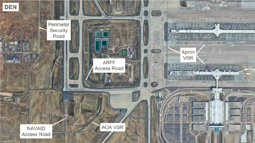
Figure 2. Examples of VSR types.
- access for mutual aid vehicles, ambulances, and other emergency operations and equipment (FAA AC 150/5300-13B 2022).
- Perimeter Security Road: These roadways are placed alongside the perimeter fence for inspection and monitoring. A TSA security vulnerability assessment may justify the installation of a perimeter security road to facilitate monitoring of the AOA fence line at a certificated airport. (FAA AC 150/5300-13B 2022).
- Navigational Aid (NAVAID) Access Road: Some NAVAID facilities (e.g., precisions approach path indicator, glide slope, localizer, runway visual range sensors, wind cones, and so forth.) are fixed-by-function. NAVAID equipment often resides within or near runway safety areas (RSAs) and object-free areas (OFAs) of runways and taxiways. These roadways provide access to these facilities for inspection, monitoring, and maintenance (FAA AC 150/5300-13B 2022).
VSRs primarily reside in non-movement areas (e.g., airfields and non-controlled apron areas) but may also be present in movement areas of space-constrained airports. Denver International Airport (DEN) indicated that its airport maintains a letter of agreement with its ATCT, allowing vehicles to cross taxiways in the movement area on designated VSRs without controller coordination. Other airports indicated that drivers are restricted to specific routes or areas within the AOA.
AC 150/5210-20A states that “airport operators should keep vehicular and pedestrian activity in the movement and safety areas of the airport to the minimum required for operations, and these areas should be limited to vehicles necessary to support the operation of aircraft, cargo, and passenger operations, emergency services, and maintenance of the airport.” The AC also indicates that vehicles should use VSR or public roads and avoid crossing movement areas whenever possible.
Vehicles and Personnel
The types of vehicles that operate on VSRs are wide ranging and vary between airports. Airports may have varying levels of passenger air carrier, cargo, military, and GA activity. In airports with passenger air carrier activity, many of the vehicles on the VSRs near the terminal area are related to supporting aircraft ground operations, including passenger buses, aircraft towing equipment, potable water vehicles, lavatory trucks, aircraft fueling pump trucks, baggage vehicles and belt loaders, aircraft stairs, catering trucks, aircraft maintenance trucks, and other aircraft servicing vehicles. Similarly, VSRs in the vicinity of cargo areas of an airport have cargo tractors and dollies, as well as cargo platform loading vehicles. GA and military aprons may have a mix of these vehicles operating on VSRs near these facilities (Ricondo & Associates, Inc., et al. 2013).
Other vehicles operating on VSRs are airport and airline operations and police vehicles, ARFF and emergency vehicles, aircraft fuel tanker trucks, aircraft deicing trucks, snow removal equipment, pavement sweepers/cleaners, tractors, airport maintenance vehicles, and delivery trucks. One of the interview questions related to identifying critical and unique vehicles that operate on their VSRs. Airport personnel reported mostly airport-related vehicles operating on their VSRs but indicated several critical vehicles also operate on their VSRs. The heaviest vehicles reported by airport personnel were towbarless towing vehicles (TLTVs), construction vehicles such as dump trucks, and those carrying large quantities of liquids—namely, fuel tanker trucks, ARFF vehicles, and aircraft deicing-related vehicles. A review of vehicle manufacturer’s specifications indicates that the heaviest vehicles that typically operate on VSRs are 8 × 8 ARFF trucks that carry over 5,000 gallons of fluid (max weight of 124,000 pounds), fuel trucks that carry over 15,000 gallons (max weight of 150,000 pounds), TLTVs (max weight of 70,000 pounds), and deicing vehicles (max weight of 55,000 pounds). Several airports reported that semi-trailer
trucks are present on their VSRs for delivering goods to terminal buildings. U.S. federal regulations limit single-trailer semi-trucks operating on federal highways to a maximum weight of 80,000 pounds (Title 23 CFR Part 658 2019). Two of the interviewed airports reported that their rules and regulations restrict or require approval of vehicles exceeding a maximum gross vehicle weight or axle weight limit.
The airports reported that the widest and longest vehicles operating on VSRs were fueling trucks (lengths up to 50 feet), ARFF vehicles (widths up to 13 feet and lengths up to 52 feet), passenger buses (widths up to 16 feet and lengths up to 60 feet), TLTVs (widths up to 15 feet), and semi-trailer trucks (lengths up to 75 feet). The airports also indicated that many snow removal vehicles are too wide for VSRs and typically operate only on aircraft pavement of runways, taxiways, taxilanes, and aprons.
TLTVs were discussed in several of the interviews. These vehicles are often present at airports with widebody aircraft activity or significant aircraft maintenance activity. One of the interviewees indicated that their airport restricted TLTVs according to their rules and regulations to prevent them from operating on the airfield. Other airports have airlines with a letter of agreement with the local ATCT that allows airlines to operate TLTVs on the airfield without towing an aircraft. During the interviews, one of the airports indicated that the width and low clearance of TLTVs are better suited to operate on taxiways/taxilanes than on VSRs.
Appendix C identifies several airport vehicles that operate at airports, including a description of the vehicle, the typical maximum length, width, inner turn radius, and weight for select vehicle types.
Dimensions and Maneuvering
The latest version of AC 150/5300-13B was published on March 31, 2022, and Section 6.5 provides standards and design considerations related to the various types of airfield roadways within the AOA. The previous version of the AC, published in 2014, did not include standards or guidelines for the planning and design of airport roadways (FAA AC 150/5300-13A 2014).
The dimensions of AOA VSRs are primarily driven by the type of vehicles utilizing the roadway. Most surveyed airports indicated that VSR lanes are 10 to 12 feet wide, consistent with FAA guidelines identifying typical VSR widths of 20 to 25 feet (FAA AC 150/5300-13B 2022). The FAA provides no guidelines on design speed limits or for providing VSR shoulders. As discussed in the previous section, several vehicles operating within the AOA have widths over 12 feet, such as TLTVs, ARFF vehicles, snow removal equipment, and cargo loaders.
ACRP Report 96: Apron Planning and Design Guidebook recommends that planners coordinate with airport operators and tenants during the planning process to understand the type, size, and frequency of vehicles operating on the aprons (Ricondo & Associates, Inc., et al. 2013). Two of the interviewed airports indicated their airport had VSRs with lane widths of up to 20 feet to accommodate wider vehicles with larger turning radii, such as fuel trucks, snow removal equipment, or buses. As shown in Figure 3, different lane widths are used for the main VSR (20-foot lane width) and the tail-of-stand VSR near the terminal (10-foot lane width) at Ontario International Airport (ONT). At DEN, a wider roadway has been constructed adjacent to a VSR to allow snow vehicles to stage without interrupting the flow of vehicles on the primary VSR (Figure 4).
FAA guidelines indicate that perimeter security roads should be 12 to 15 feet wide (FAA AC 150/5300-13B 2022). At the interviewed airports, perimeter roads, when not part of an AOA VSR, are typically configured to accommodate passenger vehicles traveling along the security fence in a single direction. Similarly, NAVAIDs access roads were reported to be constructed with a wider single lane to accommodate maintenance vehicles.
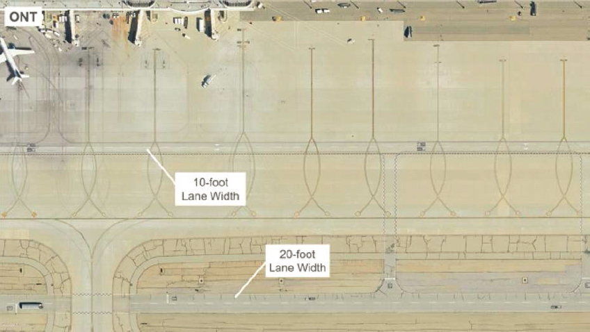
Figure 3. Varying VSR lane widths at ONT.

Figure 4. Snow removal equipment VSR at DEN.
ARFF vehicles typically have designated roads to ensure unimpeded access to meet response performance requirements in Part 139. AC 150/5300-13B recommends that the width of ARFF access roads allows for two-way traffic to accommodate emergency vehicles. The AC also indicates that typical ARFF roadway widths range from 20 to 30 feet and that turn radii can accommodate fully loaded ARFF vehicles with speeds of up to 70 miles per hour (mph).
None of the interviewees indicated any design standards related to the centerline or edge radii of VSRs. A review of aerial photography of the interviewed airports showed that the edge radii of VSR intersections ranged from 20 to 40 feet. The AASHTO guidebook A Policy on Geometric Design of Highways and Streets provides design research and practices for geometric design, including information on turning paths and vehicle turning radii. Vehicle maneuvering software that works within computer-aided design platforms can simulate the movement of airport ground vehicles to ensure roadway layouts provide sufficient clearances.
Traffic Volume and Capacity
AC 150/5300-13B recommends considering the frequency of ground vehicle traffic in non-movement areas but does not suggest a required number of lanes for a VSR. The Highway Capacity Manual is the standard manual for quantifying traffic congestion and highway capacity (TRB 2022).
Most interviewees did not report any issues with congestion and had not completed any traffic volume studies. Indianapolis International Airport (IND) and DEN reported having dual-lane VSRs at their airports to accommodate higher traffic volumes, facilitate slow vehicle passing, and accommodate turn lanes. The dual-lane VSRs at DEN were planned as part of the original construction of the airport. At IND, a cargo carrier completed a study to estimate traffic volumes caused by buses continuously operating between a cargo facility on one side of a runway and a pilot center on the opposite side. The study determined that additional lanes were needed to accommodate traffic, and travel time could be reduced by constructing a shorter dual-lane VSR between the facilities and allowing the passing of slower-moving vehicles (see Figure 5). A VSR adjacent to the terminal area at Seattle-Tacoma International Airport (SEA) incorporates a slow lane to aid in the movement of vehicles through the often-congested area (Figure 6).
At Nashville International Airport (BNA), the end of a pier concourse is configured with dual taxilanes that provide access from the airfield to the concourse and an adjacent concourse. Two security gates are located across the taxilanes and provide the main access point for vehicles entering the terminal areas (Figure 7). Traffic congestion between the concourse and the security gates was a continuing concern for the airport because of increased aircraft and passenger activity and potential expansion to the apron and terminal complex. The movement of aircraft and vehicles was simulated to confirm that the existing VSR configuration across the taxilanes would be sufficient.
Clearances
AC 150/5300-13B provides information on locating VSRs outside the limits of the runway and taxiway safety and object-free areas except when necessary to cross a taxiway or taxilane. The AC also states that VSRs should not be routed across runways or through an RSA. Since RSAs have grading requirements, when VSRs cross an RSA, the AC indicates that they should be constructed flush with the adjacent grade to maintain control of an aircraft during an excursion event when an aircraft departs the runway during takeoff or landing. The AC indicates that runway OFAs, which are wider than RSAs, provide an area clear of above-ground objects protruding above the elevation of the nearest point of the RSA.
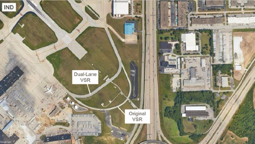
Figure 5. Dual-lane VSR at IND.
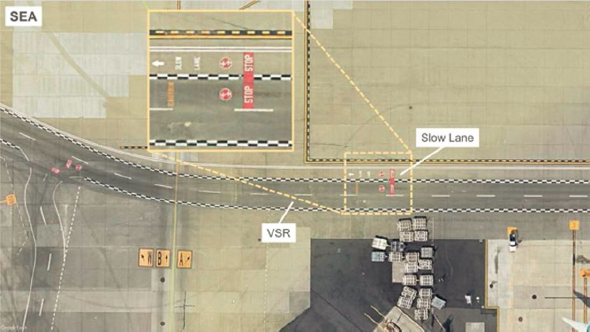
Figure 6. VSR with slow lane at SEA.
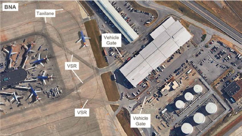
Figure 7. VSRs from security posts crossing dual taxilanes at BNA.
The AC also states that apron VSRs should follow established clearances from taxiway/taxilane centerlines, and where this is not achievable, surface markings such as hold lines and signs should be provided to ensure adequate distance from aircraft. These signs and markings increase driver situational awareness. Apron VSRs should also provide a minimum clearance of 10 feet from parked aircraft, but this can be reduced to 6 feet if there is at least 5 feet of vertical clearance between the nearest point of the aircraft and the top of the tallest vehicle expected to operate on the apron VSR.
For perimeter security roads, TSA guidelines indicate that the effectiveness of perimeter fencing is improved by having clear areas on both sides of the fence, because doing so facilitates surveillance and maintenance of fencing. TSA suggests that 10 to 30 feet of area be cleared along fences to ensure no objects can be climbed, including parked vehicles (TSA 2017).
Two of the interviewed airports had VSRs that travel through an RSA. At Hollywood Burbank Airport (BUR), vehicles traveling on a VSR located at the approach end must stop and look for aircraft on approach before proceeding through the RSA for Runway 26 (Figure 8). A VSR at SEA is situated under a paved portion of RSA and the approach lighting system (Figure 9). The airport has experienced issues with vehicles striking the bridge support structure and the light system, and height clearance bars have been implemented to warn vehicles of the limitation. The airport also has a VSR inside the runway OFA but outside the RSA. The ATCT does not control the use of the VSR since vehicles on the roadway are situated below the edge elevation of the RSA. The airport also indicated that the proximity of its VSR to the perimeter fence has resulted in vehicles damaging the fence. The airport also has mounted mirrors in some areas where the VSR runs along the fence so drivers can see oncoming vehicles around blind corners.
Design Considerations
AC 150/5300-13B identifies several design considerations for VSRs. The AC recommends that VSRs within RSA be flush to the adjacent grade to allow pilots to maintain control of an aircraft during an excursion event. The AC also indicates that VSRs along the path of a

Figure 8. VSR through an RSA at BUR.
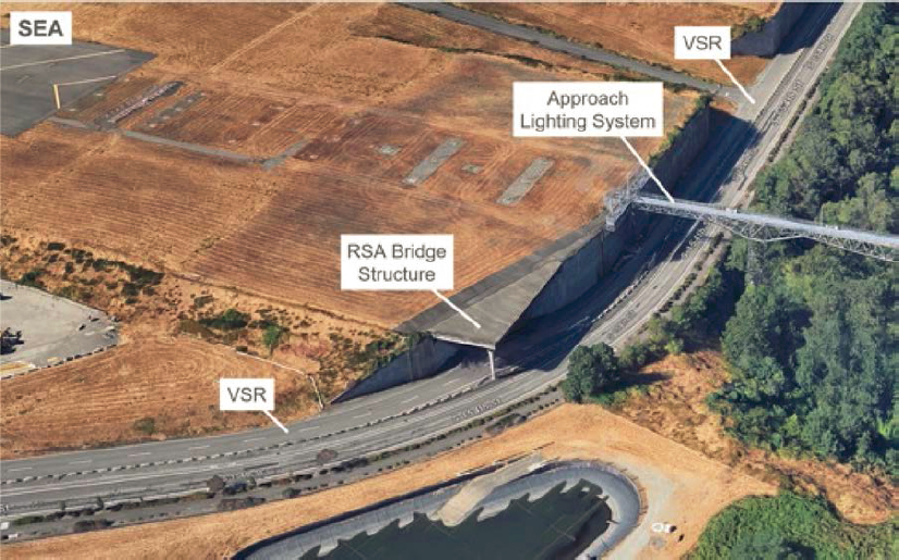
Figure 9. VSR under a paved RSA structure and approach lighting system at SEA.
taxiway bridge should have a separate bridge for vehicle use and be outside OFAs. The AC indicates that local, county, or state specifications are suitable for airfield VSRs. The load bearing of VSRs on commercial and cargo aprons is controlled by the anticipated aircraft loads, which are typically much higher than the heaviest vehicles operating at an airport. The design of GA aprons serving small aircraft should consider potential loading by heavy airport vehicles.
AC 150/5300-13B recommends that ARFF access roads be accessible in all weather conditions. As a design consideration, the AC also indicates that VSRs should not be used as a primary ARFF access route in meeting Part 139 response times.
The AC also recommends that perimeter roads with a low volume of traffic should be composed of a compacted gravel surface that conforms to local, county, or state standards for aggregate surface roadways. Paving segments of perimeter roads with higher traffic volume is also recommended in the AC. Similarly, NAVAID access roads should also be constructed of compacted gravel surface. Gravel roads should be paved within 300 feet of an apron, taxiway, or runway to prevent debris from tracking onto airfield movement areas. The construction of VSRs adjacent to fence lines should consider the potential for runoff to erode soil and create openings below the fence.
The interviewees reported various standards that were used to design VSRs. Several airports reported using state department of transportation standards for roadways, while others adhered to local county specifications. One of the airports reported that they had created design guidelines for VSRs to ensure that the maximum weight of ARFF vehicles could be accommodated. The weight limit at the edge of a VSR bridge was a concern at SEA. The VSR was reduced to one lane, and a marking was added to prevent vehicles, most notably ARFF vehicles, from traveling on that portion of the bridge (Figure 10).

Figure 10. Restricted area marking and single-lane bridge VSR at SEA.
Building Entrances, Tunnels, and Ramps
VSRs often enter buildings to access baggage facilities, interior tunnels, or other facilities. VSRs are also frequently routed through a building, such as a pier concourse, to allow travel to the other side without driving around the building. Most interviewed airports with passenger airline service had VSRs that entered a terminal building.
There is no information on the recommended height limits for VSRs entering buildings. Several of the interviewees reported height clearances at their airports between 8 and 9 feet, and floating or fixed-height clearance bars were used to avoid damage to the building. Some airports reported using stop signs or flashing lights at building entrances or within the building. Pedestrian crossings were also reported at these locations, often with flashing pedestrian crossing signs. At Pittsburgh International Airport (PIT), automatic curtain doors prevent heat escape during winter months.
The interior tunnel at DEN serves as a VSR for baggage and other vehicles traveling between the terminal and three airside concourses. It is restricted to vehicles powered by electricity or compressed natural gas, except for responding emergency vehicles. DEN also has single-lane tunnels as part of its VSR system. The tunnels have stop signs with flashing lights at each end, and vehicles must yield to oncoming traffic (see Figure 11). These airfield tunnels do not have restrictions on hazardous materials. Miami International Airport (MIA) has a midfield tunnel under a runway and parallel taxiways. The tunnel has a vehicle height clearance of 14 feet and a restriction on vehicles exceeding a width of 8.5 feet. Fuel trucks and fuel hydrant pump vehicles are not permitted in the tunnel.
VSRs at the head-of-stand are often placed under fixed passenger loading bridge segments with height clearances. Several interviewees indicated that driving or parking under passenger loading bridges or within their operating area was prohibited at their airports. Driving underneath passenger loading bridges was allowed at Portland (Oregon) International Airport (PDX) only on designated and marked roadways.
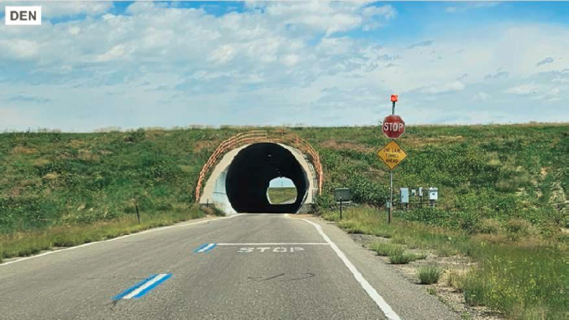
Figure 11. Single-lane airside tunnel at DEN.
Markings
FAA AC 150/5340-1M indicates the types of markings that should be used for VSRs that cross paved areas used by aircraft. These markings include roadway edge markings, roadway edge zipper-style markings, roadway centerlines, and roadway stop line/bar (Figure 12). The AC also indicates that roadways not located on aircraft maneuvering areas should utilize roadway markings consistent with the Manual on Uniform Traffic Control Devices for Streets and Highways (MUTCD; U.S. Department of Transportation 2023). The AC also indicates that markings used by aircraft should not be used for VSRs, and roadway markings should be kept at least 2 feet away from non-movement area boundary markings. The AC indicates that roadway edge zipper-style markings may be used where the airport operator determines that roadway edges need enhanced delineation.
The FAA does not provide guidelines on roadway markings beyond that recommended in AC 150/5340-1M. The latest version of the AC 150/5300-13B indicates that industry best practices
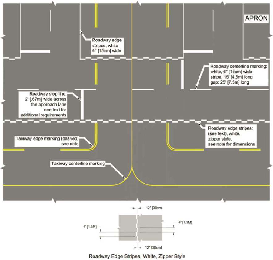
Figure 12. FAA vehicle roadway markings.
and guidelines are available from ACI and A4A for select apron markings not addressed by FAA standards and that installation of such markings should be coordinated with affected parties.
ACI provides guidelines similar to the FAA on the types of centerline and edge markings for apron service roads but recommends double solid white lines to identify the limits of vehicle activity instead of the zipper-style edge lines recommended by the FAA. The ACI guidelines recommend using zipper-style edge lines on VSRs that cross taxiways or taxilanes and using a vehicle stop sign with crossing aircraft, as shown in Figure 13. The ACI guidelines also include examples of providing stand identification/numbers on service roads (ACI 2017). ICAO design manuals have minimal information on VSR markings and reference the best practices in the ACI handbook (ICAO 2021).
A4A provides recommendations for roadway edge and centerline markings, including pedestrian crossings, painted speed limits, and directional signs. It also states that a risk assessment should be completed before any changes to roadway marking schemes (A4A 2017). ACRP Synthesis 122: Airfield Apron and Ramp Surface Markings included survey questions on vehicle markings used on aprons and provided examples of VSR markings at several airports (Polsgrove 2023).
The use and style of stop and yield markings were inconsistent at the interviewed airports. Some airports only used stop markings at intersections, while others used a combination of stop and yield markings depending on the intersection configuration or location of taxilanes/taxiway crossings. In the terminal area of BNA, no yield or stop markings are used at VSR intersections or before taxilane crossings. Several examples of stop, yield, and speed limit markings are shown in Figure 14. Other markings were used at the interviewed airports and included text on VSRs indicating to watch for trucks, one-way/do not enter warnings, wait for escort positions, and information for bus drivers operating on VSRs.
Several interviewed airports reported implementing unique markings as part of their VSR system. PDX has incorporated a red line of demarcation around the terminal area to aid in the training, situational awareness, and prevention of vehicles driving onto movement area taxiways
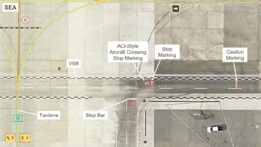
Figure 13. ACI-style aircraft crossing stop sign at SEA.
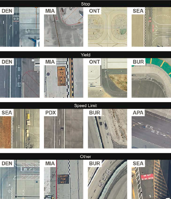
Figure 14. Stop, yield, speed limit, and other markings at various airports.
(Figure 15). The line of demarcation is paired with a zipper-style line and the non-movement boundary line. The limited apron depth prevents the separation of the line of demarcation and non-movement area boundary line from meeting the 2-foot separation recommendation in AC 150/5340-1M. Zipper-style lines are used along the boundary with the movement area, but the interior apron adjacent to non-movement taxilanes is outlined with a solid roadway edge line (Figure 16). Conversely, the zipper-style line is used to outline all VSRs in the terminal area at IND (Figure 17).
SEA also uses a red line of demarcation similar to PDX at the end of its terminal and cargo apron (Figure 18). The airport indicated in the interview that it uses a standard if available; otherwise, a risk assessment is completed to determine how to configure VSRs and markings.
At BUR, zipper-style road edge lines and stop markings are used on VSRs crossing apron entrances and adjacent to a helicopter landing area (Figure 19). Drivers are responsible for stopping and ensuring no helicopters are on approach before proceeding.
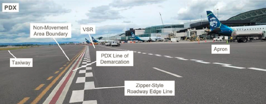
Figure 15. “Line of demarcation” used at PDX.

Figure 16. Zipper-style and solid edge markings at PDX.

Figure 17. Zipper-style markings at IND.

Figure 18. Line of demarcation at SEA.
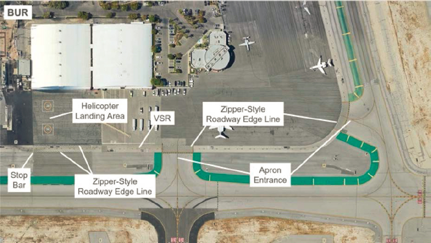
Figure 19. A zipper-style line on VSR adjacent to a helicopter pad at BUR.
At DEN, specific airfield VSRs, known as limited access routes, are restricted to users with an operational need, such as airport operations personnel, drivers on a designated haul route, or employees requiring access to a remote workplace. These roadways are signed at their entrances, and the entirety of the VSR has white centerlines with blue borders (Figure 20). The centerline and signs provide situational awareness for airfield drivers.
At ONT, VSRs in some locations are configured with a solid centerline to indicate that passing slow-moving vehicles is not allowed. The airport also uses a combination of concrete barriers (Jersey barriers or K-rail) and frangible delineators to prevent vehicles from entering restricted areas. The airport indicated that frangible delineators allow the edge of the road to be identified but prevent vehicles from being damaged if they deviate from the roadway (Figure 21).
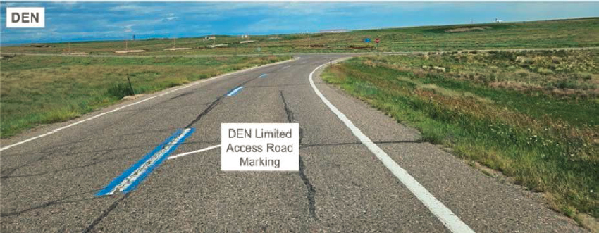
Figure 20. Limited access route centerline marking at DEN.
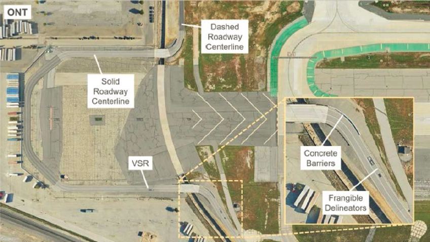
Figure 21. Solid VSR centerline marking and location of frangible delineators and concrete barriers at ONT.
Personnel from PDX indicated that pilots of small aircraft have taxied onto VSRs after mistaking them for taxiways. PDX has used yellow “X” markings on VSRs near the GA apron and other locations throughout the airfield to identify that it is closed to taxiing aircraft (Figure 22).
Another issue raised by airports was the difficulty of distinguishing white VSR markings on the light-colored background of concrete pavement. Some airports addressed this by painting the centerline white and bordering it with black paint (Figure 23). FAA AC 150/5340-1M indicates that this is a proven method for helping enhance the contrast of surface paints but that glass beads should not be used in the black paint. The AC recommends the use of black borders for other markings, such as roadways, on concrete or asphalt pavement that is over two years old. The AC does not provide any guidelines on the use of glass beads in paint for roadway markings.
An issue that two interviewees raised was that paint used for roadways often does not hold up well in the apron environment. Both airports indicated they are using thermoplastic since it is much more durable, and the higher reflective bead materials in the product do not fade as quickly as standard marking paint. The airports reported using thermoplastic for markings in high-traffic areas, such as painted stop and yield signs at vehicle and aircraft intersections. They also reported using thermoplastic for markings that are more difficult to paint with pavement marking equipment, such as zipper-style edge markings. A manufacturer of thermoplastic markings indicated that the material lasts approximately six to 10 times longer than paint. One of the airports reported that the thermoplastic stop lines also act as a rumble strip because of their thickness.
Signage
AC 150/5340-18G provides information on signage for VSRs, including installing standard highway stop or yield signs at roadway intersections with runways and taxiways. The AC also indicates that airports should install “DO NOT PROCEED CONTACT ATC” signage on VSRs
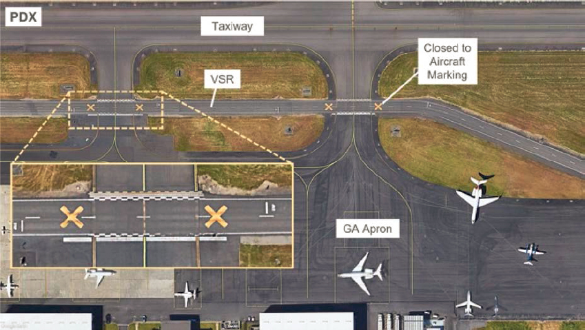
Figure 22. VSR with an “X” marking to signify it is closed to aircraft at PDX.
with roadways that intersect runways and taxiways at airports without a letter of agreement with ATCT allowing drivers to cross taxiways without clearance (Figure 24). The AC also indicates that unlighted runway and taxiway signage should be installed to provide situational awareness to drivers. The AC indicates that signage should conform to the MUTCD but acknowledges that criteria may need to be altered to avoid conflicting with the airfield environment, such as aircraft wingtip clearances and the effects of jet blasts.
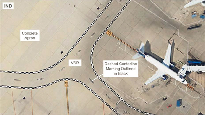
Figure 23. The VSR centerline with a black border on a concrete apron at IND.
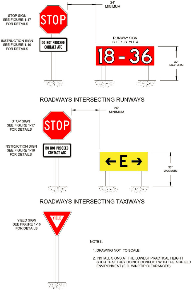
Figure 24. Stop and yield sign assembles for VSRs intersecting runways and taxiways.
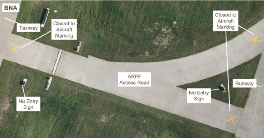
Figure 25. An ARFF access road with an “X” marking to signify it is closed to aircraft at BNA.
ICAO guidelines recommend using road-holding position lights to control vehicular traffic at runway and roadway intersections. The lights consist of red and green signals or flashing red lights instructing vehicles to hold or proceed (ICAO 2021). None of the interviewees reported utilizing road-holding position lights.
ACI provides guidelines that road signs should replicate those used on public roads to ensure driver familiarity. The guidelines also state that signage should be provided to agreed standards, be of adequate size, and be placed in good locations with clear visibility lines to those expected to see them. (ACI 2010). ACI also provides examples of signs, such as jet blast warning signs, typical road traffic signs, and emergency signs for apron users (ACI 2017). In the apron area, elevated signs are often prohibited, or not practical, and painted markings are used (Ricondo & Associates, Inc., et al. 2013).
At BNA, an ARFF access road that enters a runway was being confused as a taxiway by small aircraft pilots because of the roadway width. To better distinguish the ARFF access road, the airport incorporated yellow “X” markings (Figure 25). It also installed no entry signs and frangible delineators to emphasize that the pavement was not available to aircraft (Figure 26). The airport chart was also updated to emphasize that the pavement was for vehicle use only (Figure 27).
General Aviation Considerations
ACRP Report 113: Guidebook on General Aviation Facility Planning guides the planning of GA facilities. The report indicates that remote vehicle parking areas to serve hangar complexes should be considered to accommodate users unfamiliar with the airport. The report also recommends limiting the amount of access that passenger vehicles have to the airside of an airport to enhance safety and reduce the possibility of vehicle/aircraft incidents (Sander et al. 2014).
At most of the interviewed airports not subject to Part 1540, the private vehicles of GA hangar users were often restricted to adjacent parking lots. Airport users entered the airfield on foot through a fence, similar to the example shown in Figure 28. Most airports had escort procedures to allow private vehicles to access airside hangars.
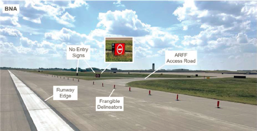
Figure 26. An ARFF access road with No Entry signs and flexible delineators at BNA.
At Centennial Airport, Colorado (APA), one of the busiest GA and reliever airports in the United States, private vehicles are allowed on specific VSR segments to access hangar facilities. As shown in Figure 29, the VSR for the hangars is painted on a taxiway accessing the hangar area. The airport indicated that hangar users are provided with airport rules and a map of the hangar area, but no formal driver training is provided. The airport asks these drivers to use the gate closest to their hangar and always give way to aircraft.
Traffic Flows and Layout
There are minimal industry guidelines on the layout of VSRs. Much of the information focuses on the dimensions, clearance, marking standards, and design considerations provided in AC 150/5300-13B. This AC recommends limiting the number of VSR crossings of taxiways and taxilanes and designing them to cross perpendicular to the taxiway/taxilane centerline. The AC also states that VSRs that parallel taxiway bridges should be constructed on a separate bridge.
The interview discussions indicate that certain vehicles often continuously circulate through an airfield, such as airport operations for security and airfield inspections and airport maintenance vehicles. The flow of other vehicles throughout an airfield largely depends on the locations of facilities and the need for vehicles to travel between them. Several examples were identified during the interviews and include the following:
- Buses transporting cargo pilots between a cargo facility and a pilot facility
- Fueling trucks driving between a fuel farm and cargo or GA facilities located on the other side of the airfield
- Airline catering and cargo vehicles driving between the terminal area and their associated facilities
- Deicing pads located in the middle of the airfield and inaccessible from public roads.
Two interviewees indicated their goal was to separate non-movement and movement area users as much as possible. One of the interviewees stated that it is challenging to provide accessible non-movement area VSRs around the airfield while ensuring it is not so well-connected to the movement area that drivers get distracted and end up in the wrong place.
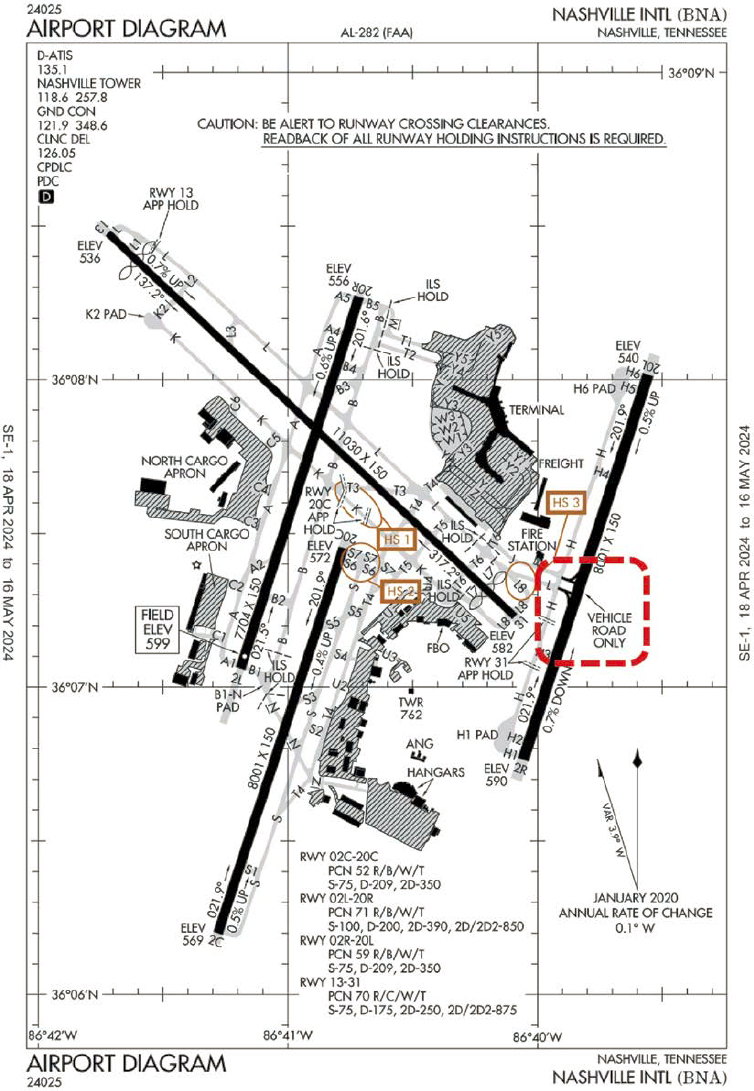
Figure 27. The BNA airport diagram with the ARFF access road emphasized as a vehicle road only.
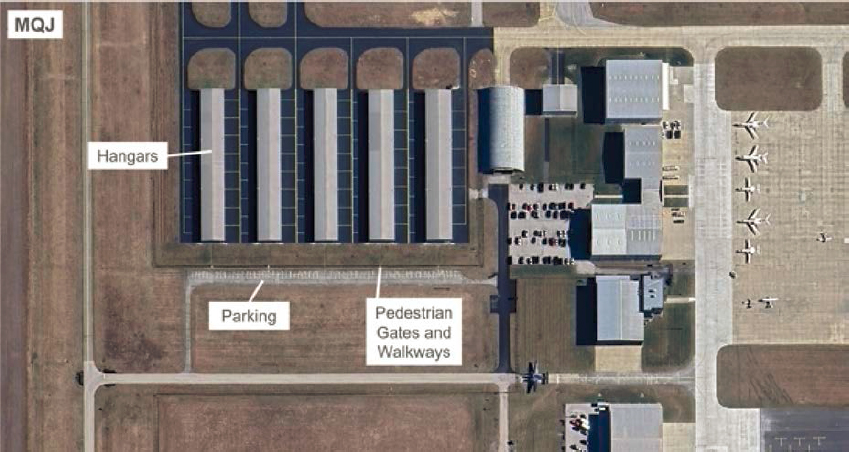
Figure 28. Vehicle parking area for hangars at MQJ, Indianapolis Regional Airport.
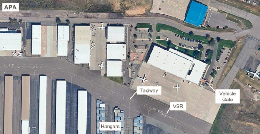
Figure 29. A VSR that coincides with a taxiway at APA.
Distinctive Vehicle Service Road Layouts
The discussions during the airport interviews revealed multiple distinctive VSR layouts. The following describes and shows some of these VSR layouts.
A three-way intersection with two dual-lane roadways at DEN has resulted in vehicles accidentally turning onto taxiways. As shown in Figure 30, vehicles traveling northbound and turning westbound must stop short of the taxiway (a) and, if it is clear, proceed through or turn at
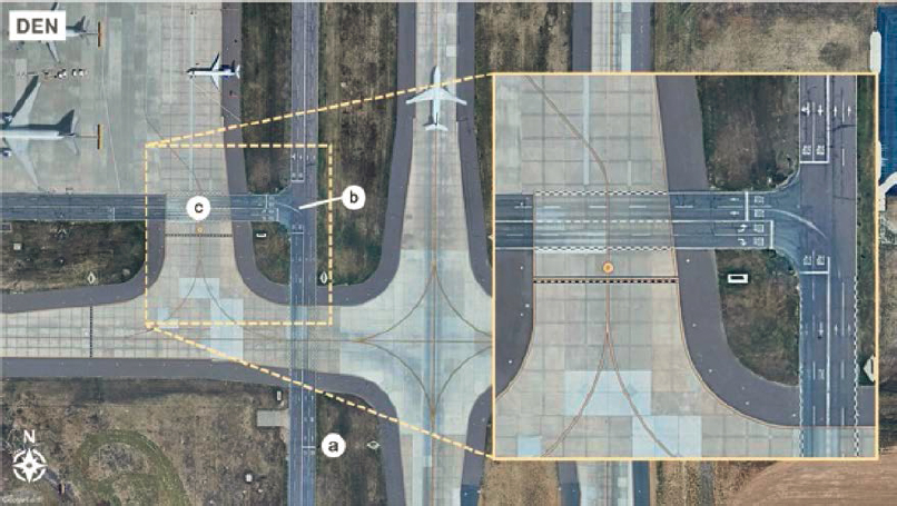
Figure 30. A complex VSR intersection at DEN.
the intersection (b) and ensure the apron entrance (c) is clear before proceeding. Most vehicle movements through this section must navigate two stop signs. This intersection and several others throughout the non-movement area have been identified as vehicle hot spots for drivers, similar to the FAA’s practice of identifying complex airfield locations for pilots.
At BUR, limited space and the location of a support building require the VSR to enter the taxiway OFA (Figure 31). A yield sign (a) is for holding vehicles if an aircraft is taxiing on the adjacent taxiway (b). If the taxiway is clear, the vehicle can proceed on the VSR to the SIDA entry point (c).
At SEA, limited apron space is available, and a VSR is constrained in areas to a single lane (Figure 32). In the figure, a vehicle traveling from left to right must hold before the single-lane bridge (a) and again after the bridge (b) before proceeding on the single-lane VSR. A bypass area (c) allows vehicles to hold at the apron if necessary.
SEA also has a unique layout where VSRs enter an apron alley but discontinue after about 200 feet to accommodate dual taxilanes (Figure 33). The taxilane alley is considered a vehicle traffic area with a reduced speed limit of 10 mph, where vehicles must see and avoid aircraft and other vehicles. In this location and other areas throughout the terminal area, a dashed line is used to identify the taxilane OFA, which in some areas contains a VSR.
ONT has a VSR between two parallel taxiways and crosses through five active taxiways (Figure 34). The airport has painted stop bars and installed lowered stop signs at all crossings. The airport reported that the most significant challenge with this VSR is the crossing of active movement areas and ensuring vehicles do not proceed when aircraft are queuing for departure at the end of the adjacent runway. The airport has created safety campaigns reminding drivers to stop for all aircraft and never assume an aircraft is giving you the right-of-way, as this has caused several movement area incursions.
At Miami-Opa Locka Executive Airport in Florida (OPF), a VSR accessing a fire station is identified with zipper-style roadway edge markings. Instead of the VSR crossing the non-movement area boundary, the boundary has been placed outside the VSR to allow vehicles to access the facility without contacting the ATCT (Figure 35). At Allegheny County Airport in Pennsylvania (AGC), private vehicles can access the VSR system and access hangars on the airfield. Because of space constraints, the VSR merges with the taxiway (Figure 36).
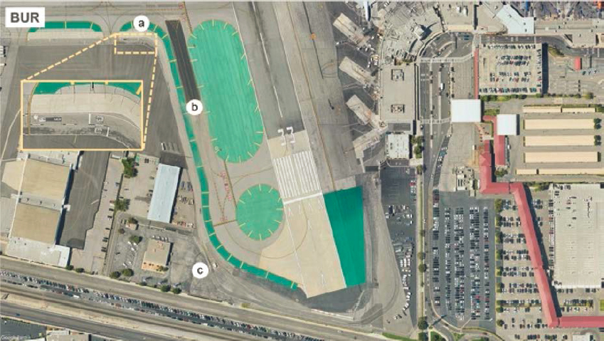
Figure 31. VSR within a taxiway OFA at BUR.
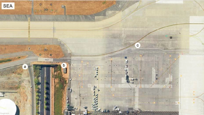
Figure 32. VSR with multiple lane reductions at SEA.
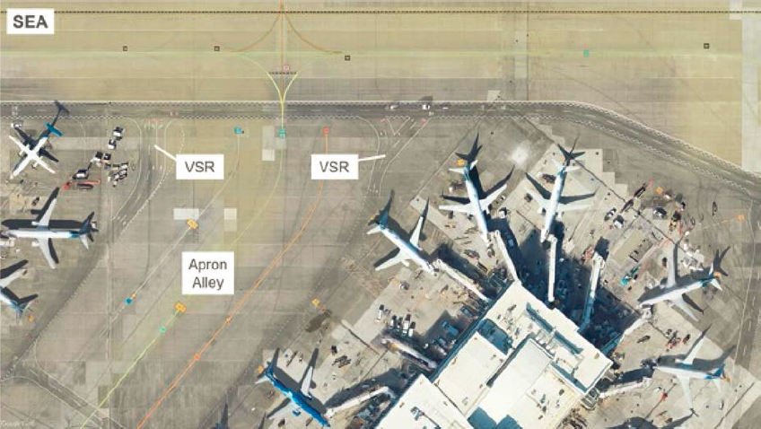
Figure 33. Vehicle traffic area at SEA.

Figure 34. The VSR crossing multiple taxiways at ONT.
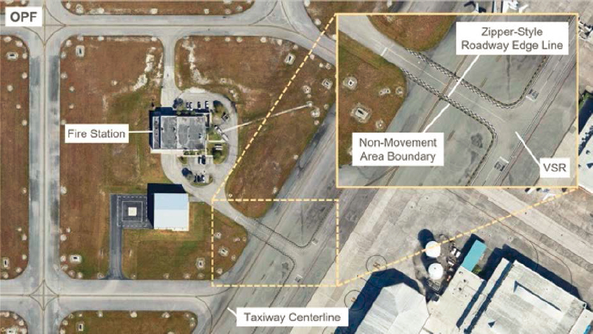
Figure 35. A non-movement boundary excluding a VSR that allows access to a fire station at OPF.

Figure 36. A VSR merges with a taxiway because of space constraints at AGC.


