Guidelines for Evaluating Crashworthiness of Sign Supports and Breakaway Luminaire Poles (2024)
Chapter: 5 Validating Analytical Program: Breakaway Sign Supports, PSST Posts
CHAPTER 5
Validating Analytical Program: Breakaway Sign Supports, PSST Posts
Sign support systems that were developed and validated under NCHRP Project 03-119 were used as the starting point in this project (NCHRP Project 22-43). Additional full-scale crash tests were identified from the literature and used under this study. Testing performed under this project by the Center for Collision Safety and Analysis (CCSA) at FOIL was used to further calibrate and validate these computer models. Comparisons between these new test results and the results from the simulations were made, and based on these comparisons, updates were made to the models such that the results would match. The main change to the model was the soil properties used in the model. The initial simulations had assumed a stronger soil strength, leading to premature post shearing and differing responses of the sign system in some tests. The tests used for validation are listed in Table 31. All validations were run again with the latest models to check that the behavior of previous and new tests could be replicated with the same modeling methodology. Summaries of these validation efforts are included in the following sections.
5.1 FOIL Test Nos. 23004, 23006, 23008, 23010, and 23012
This series of validation tests was performed on PSST sign systems with different panel sizes. A total of five tests (Test Nos. 23004, 23006, 23008, 23010, and 23012) were performed at FOIL.
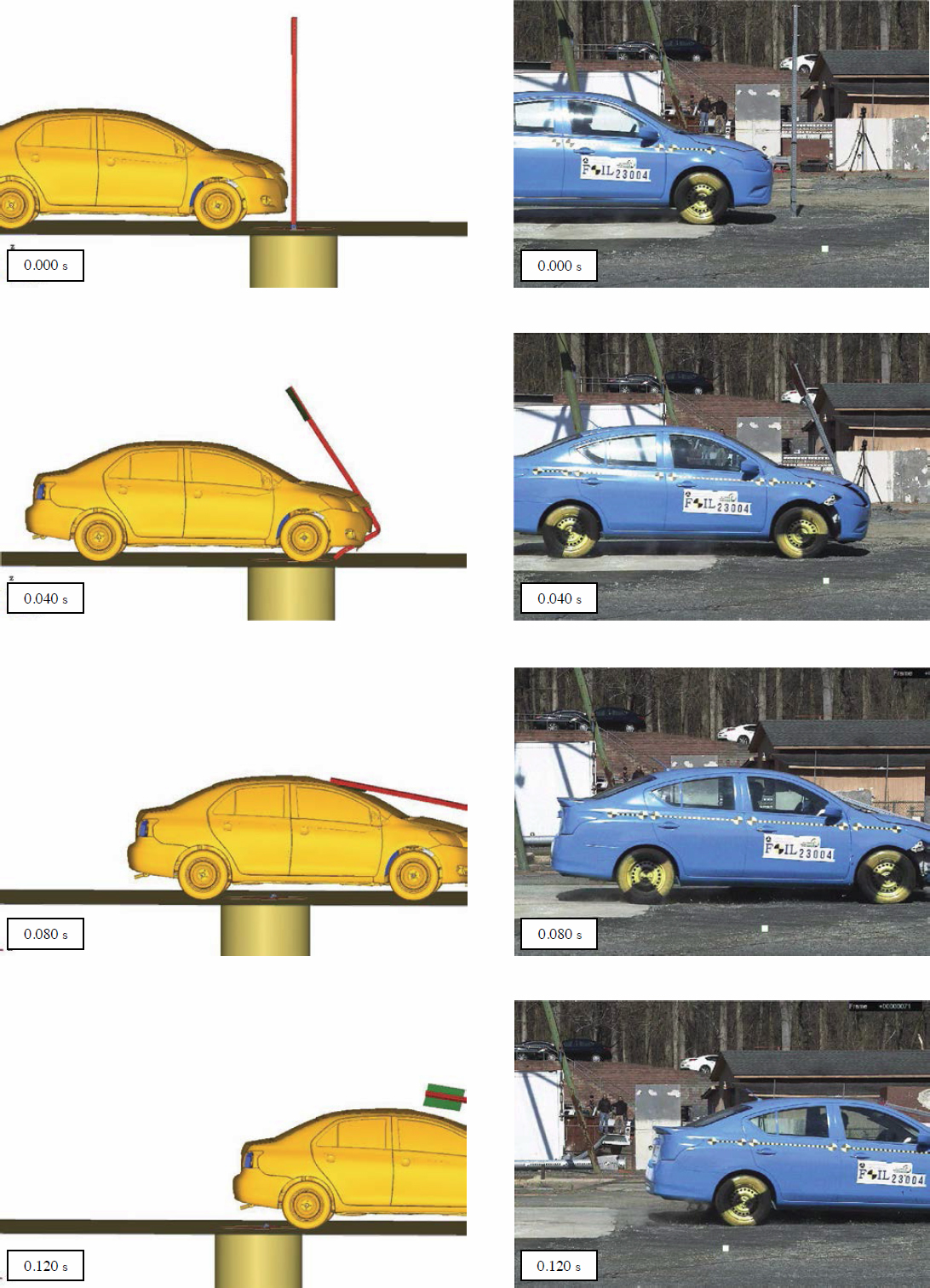
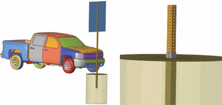
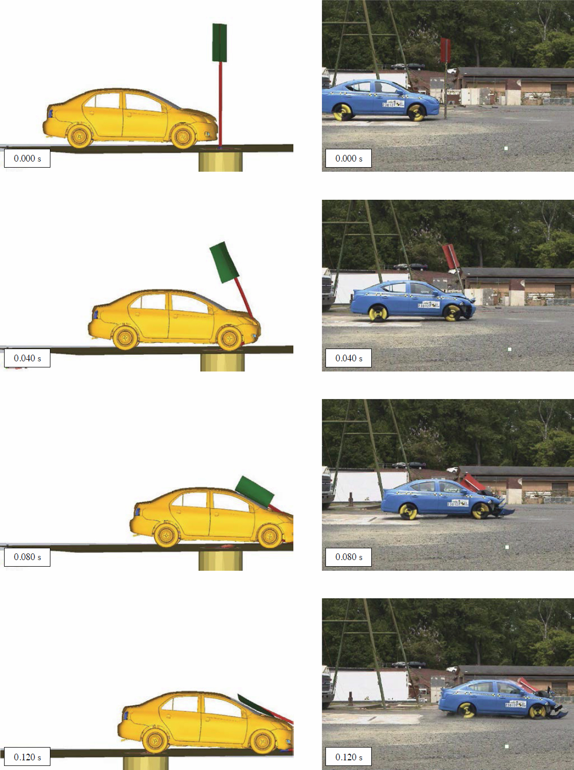
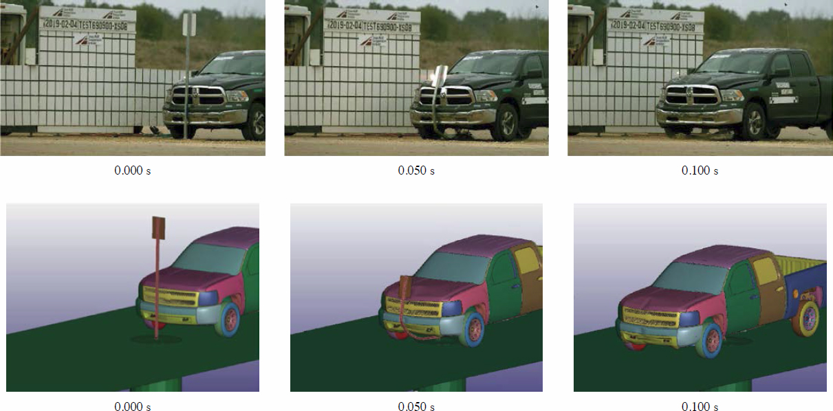
For the first test, Test No. 23004, the sign support system consisted of a 12-gauge, 2¼-in. PSST support. The system was installed in standard soil, and the overall length of the sign support system was 9 ft. The post in this system was anchored to the ground by a 38-in.-long, 12-gauge, 2½-in. PSST sleeve. The sleeve was embedded 36 in. below the ground with 2 in. above the ground. The sign support was inserted into the ground sleeve 8 in. and was 2 in. below the top of the sign panel. The PSST material was galvanized steel with ASTM A1011 Grade 50. A ![]() -in.-diameter corner bolt (Grade 5), nut, and washer were used to anchor the support to the ground sleeve. A 12-in. (width) × 18-in. (height) × 0.08-in. aluminum sign was attached to the support using two ⅜-in.-diameter hex head bolts (Grade 5) with flat washers and nuts. The sign panel was mounted at 7 ft measured from ground level to the base of panel.
-in.-diameter corner bolt (Grade 5), nut, and washer were used to anchor the support to the ground sleeve. A 12-in. (width) × 18-in. (height) × 0.08-in. aluminum sign was attached to the support using two ⅜-in.-diameter hex head bolts (Grade 5) with flat washers and nuts. The sign panel was mounted at 7 ft measured from ground level to the base of panel.
The PSST sign support model details and the simulation setup combined with the vehicle model are shown in Figure 109. Side-by-side comparison plots at different stages of the results are shown in Figures 110 and 111. The figures show the simulation results to be close to the test response; however, the cracking, tearing, and rupture of the roof are not fully captured in the simulation. The research team assumes that, when assessing the system performance, the system would fail the MASH intrusion criteria if one of the corner edges of the sign blank were to contact the vehicle’s roof or windshield.
Table 31. List of tests used for PSST validations.
| Test Type | Test Number | PSST Sign System | Speed |
|---|---|---|---|
| Full-scale: 1100C vehicle | FOIL-23004 | 2¼ in.; 12 ga. (1’ × 1.5’ Al.) 0° | 62 mph |
| Full-scale: 1100C vehicle | FOIL-23006 | 2¼ in.; 12 ga. (4’ × 5’ Al.) 0° | 62 mph |
| Full-scale: 2270P vehicle | FOIL-23008 | 2¼ in.; 12 ga. (4’ × 5’ Al.) 0° | 62 mph |
| Full-scale: 2270P vehicle | FOIL-23010 | 2¼ in.; 12 ga. (1’ × 1.5’ Al.) 0° | 62 mph |
| Full-scale: 1100C vehicle | FOIL-23012 | 2¼ in.; 12 ga. (3’ × 3’ Al.) 25° | 62 mph |
| Full-scale: 1100C vehicle | TTI-690900-XSD4-9 (FHWA Acceptance Letter SS-185) |
2 in.; 14 ga. (1’ × 1.5’ Al.) 0° | 19 mph |
| Full-scale: 1100C vehicle | 2 in.; 14 ga. (1’ × 1.5’ Al.) 0° | 62 mph | |
| Full-scale: 2270P vehicle | 2 in.; 14 ga. (1’ × 1.5’ Al.) 0° | 62 mph | |
| Full-scale: 1100C vehicle | 2 in.; 14 ga. (1’ × 1.5’ Al.) 90° | 19 mph | |
| Full-scale: 1100C vehicle | 2 in.; 14 ga. (1’ × 1.5’ Al.) 90° | 62 mph | |
| Full-scale: 2270P vehicle | 2 in.; 14 ga. (1’ × 1.5’ Al.) 90° | 62 mph | |
| Full-scale: 1100C vehicle |
TTI-469469-07-02 (Bligh et al. 2020) |
2 in.; 12 ga. (3’ × 3’ Al) Diag. 90° | 62 mph |
| Full-scale: 2270P vehicle |
TTI-476460-1-2-B (Bullard et al. 2009) |
2 in.; 12 ga. (3’ × 3’ Wood) | 62 mph |
| Component: 1,183 kg Pendulum | FOIL-19004 B & C | 2 in.; 12 ga. (3’ × 3’ Wood) | 10 mph |
| FOIL-19004 A & D | 2 in.; 12 ga. (3’ × 3’ Wood) | 24 mph | |
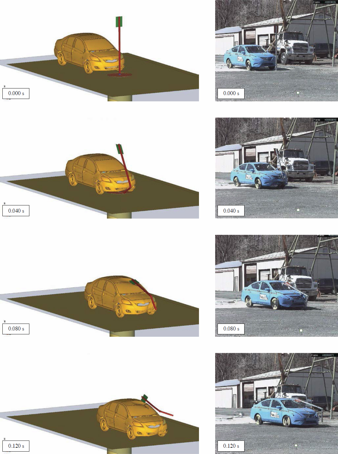
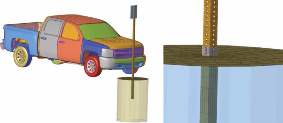
Similar to the previous test, the system in Test No. 23006 consisted of a 12-gauge, 2¼-in. PSST support installed in standard soil. The overall length of the sign support system was 12.5 ft. The post in this system was anchored to the ground by a 38-in.-long, 12-gauge, 2½-in. PSST ground sleeve. The sleeve was embedded 36 in. below the ground with 2 in. above the ground. The sign support was inserted into the ground sleeve 8 in. and was 2 in. below the top of the sign panel. The PSST material was galvanized steel with ASTM A1011 Grade 50. A ⅜-in.-diameter bolt (Grade 5), nut, and washer were used to anchor the support to the ground sleeve. A 4-ft (width) × 5-ft (height) × 0.12-in. aluminum sign was attached to the support using two ⅜-in.-diameter hex head bolts (Grade 5) with flat washers and nuts. The sign panel was mounted at 7 ft measured from ground level to the base of panel.
The PSST sign support model details and the simulation setup combined with the vehicle model are shown in Figure 112. Side-by-side comparison plots at different stages of the results are shown in Figures 113 and 114. The figures show the simulation results to be close to the test response; however, the cracking, tearing, and rupture of the roof are not fully captured in the simulation. The research team assumes that, when assessing the system performance, the system would fail the MASH intrusion criteria if one of the corner edges of the sign blank were to contact the vehicle’s roof or windshield.
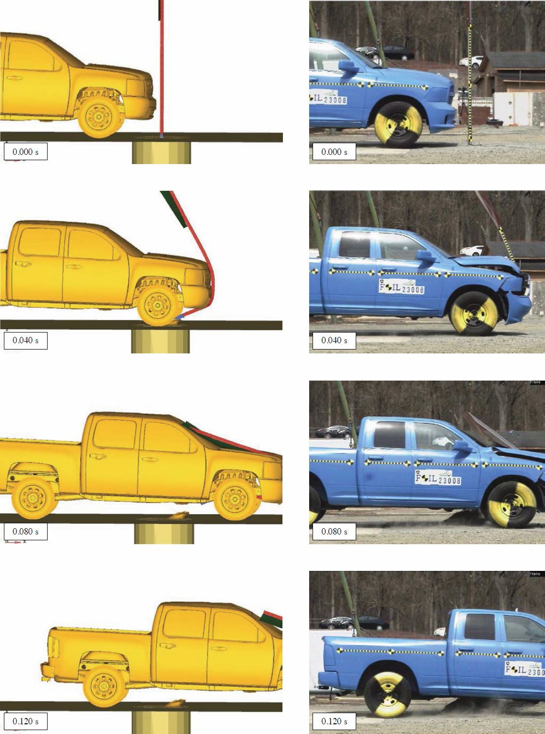
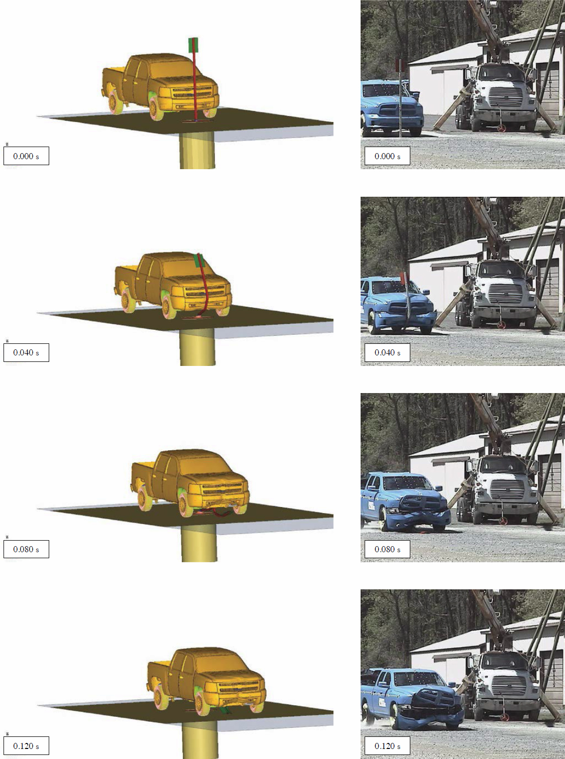
The system in Test No. 23008 consisted of a 12-gauge, 2¼-in. PSST support installed in standard soil. The overall length of the sign support system was 12.5 ft. The post in this system was anchored to the ground by a 38-in.-long, 12-gauge, 2½-in. perforated square steel tube sleeve. The sleeve was embedded 36 in. below the ground with 2 in. above the ground. The sign support was inserted into the ground sleeve 8 in. and was 2 in. below the top of the sign panel. The PSST material was galvanized steel with ASTM A1011 Grade 50. A ⅜-in.-diameter bolt (Grade 5), nut, and washer were used to anchor the support to the ground sleeve. A 4-ft (width) × 5-ft (height) × 0.12-in. aluminum sign was attached to the support using two ⅜-in.-diameter hex head bolts (Grade 5) with flat washers and nuts. The sign panel was mounted at 7 ft measured from ground level to the base of panel.
The PSST sign support model details and the simulation setup combined with the vehicle model are shown in Figure 115. Side-by-side comparison plots at different stages of the results are shown in Figures 116 and 117. The figures show the simulation results to be close to the test response; however, the cracking, tearing, and rupture of the roof are not fully captured in the

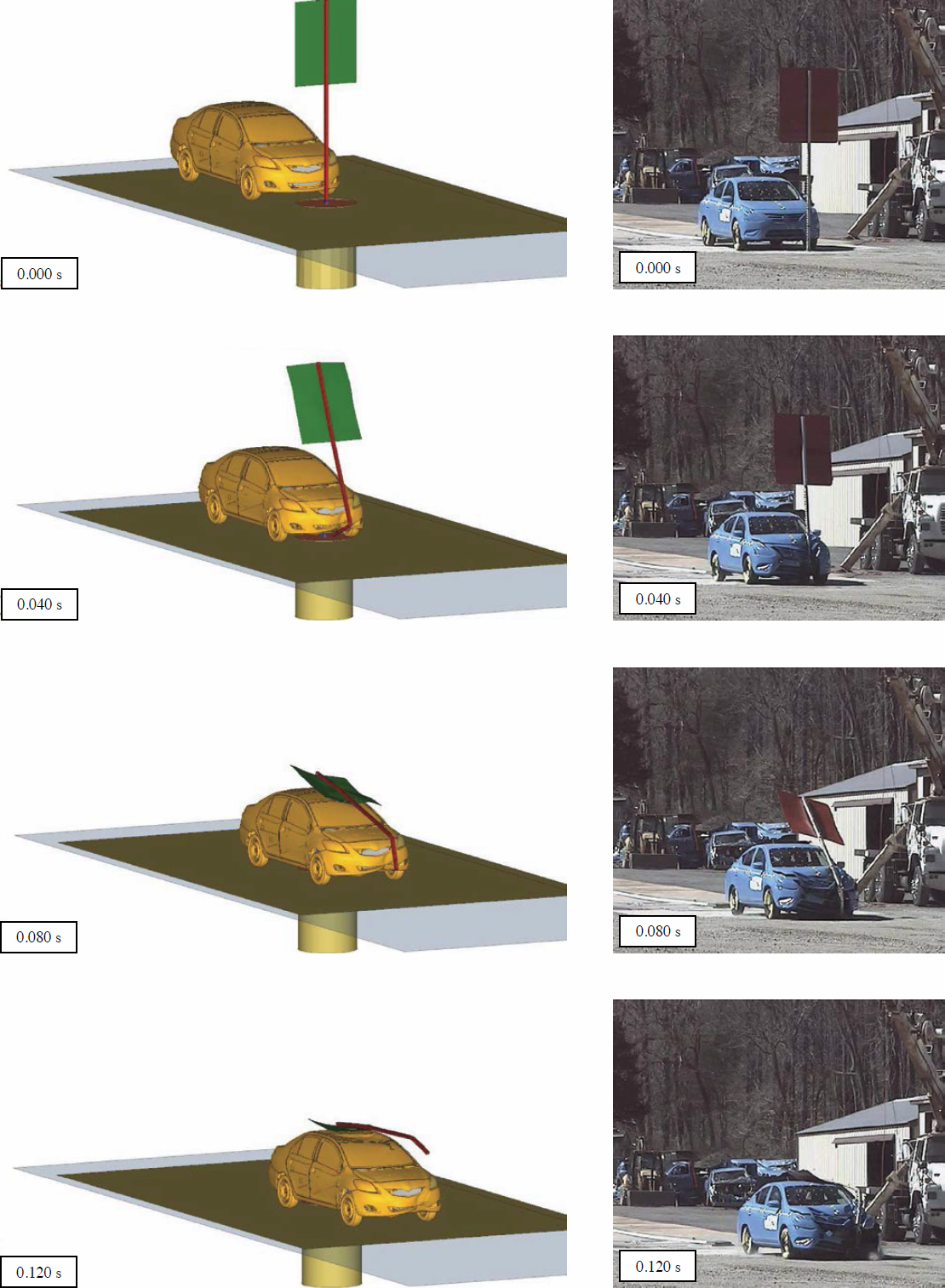
simulation. The research team assumes that, when assessing the system performance, the system would fail the MASH intrusion criteria if one of the corner edges of the sign blank were to contact the vehicle’s roof or windshield.
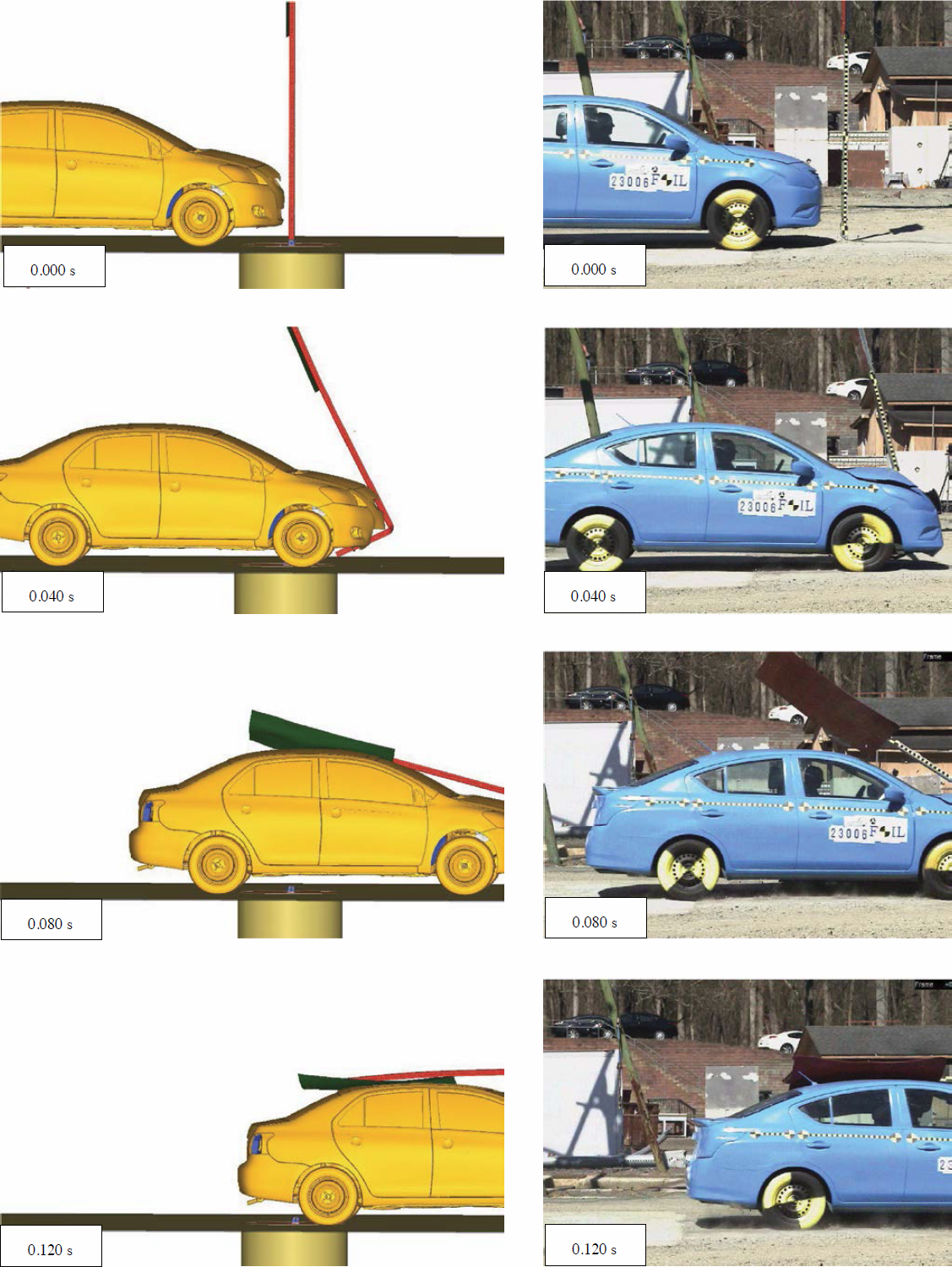
The system in Test No. 23010 consisted of a 12-gauge, 2¼-in. PSST support installed in standard soil. The overall length of the sign support system was 9 ft. The post in this system was anchored to the ground by a 38-in.-long, 12-gauge, 2½-in. PSST sleeve. The sleeve was embedded 36 in. below the ground with 2 in. above the ground. The sign support was inserted into the ground sleeve 8 in. and was 2 in. below the top of the sign panel. The PSST material was galvanized steel with ASTM A1011 Grade 50. A ⅜-in.-diameter bolt (Grade 5), nut, and washer were used to anchor the support to the ground sleeve. A 12-in. (width) × 18-in. (height) × 0.08-in. aluminum sign was attached to the support using two ⅜-in.-diameter hex head bolts (Grade 5) with flat washers and nuts. The sign panel was mounted at 7 ft measured from ground level to the base of panel.
The PSST sign support model details and the simulation setup combined with the vehicle model are shown in Figure 118. Side-by-side comparison plots at different stages of the results are shown in Figures 119 and 120. The figures show the simulation results to be close to the test response; however, the cracking, tearing, and rupture of the roof are not fully captured in the simulation. The research team assumes that, when assessing the system performance, the system would fail the MASH intrusion criteria if one of the corner edges of the sign blank were to contact the vehicle’s roof or windshield.
The system in Test No. 23012 consisted of a 12-gauge, 2¼-in. PSST support manufactured by Xcessories Squared Development & Manufacturing Inc. and installed in standard soil. The overall length of the sign support system was 10.5 ft. The post in this system was anchored to the ground by a 38-in.-long, 12-gauge, 2½-in. perforated square steel tube sleeve. The sleeve was embedded 36 in. below the ground with 2 in. above the ground. The sign support was inserted into the ground sleeve 8 in. and was 2 in. below the top of the sign panel. The PSST material was galvanized steel with ASTM A1011 Grade 50. A ⅜-in. diameter bolt (Grade 5), nut, and washer were used to anchor the support to the ground sleeve. A 3-ft (width) × 3-ft (height) × 0.125-in. aluminum sign was attached to the support using two ⅜-in.-diameter hex head bolts (Grade 5) with flat washers and nuts. The sign panel was mounted at 7 ft measured from ground level to the base of panel.
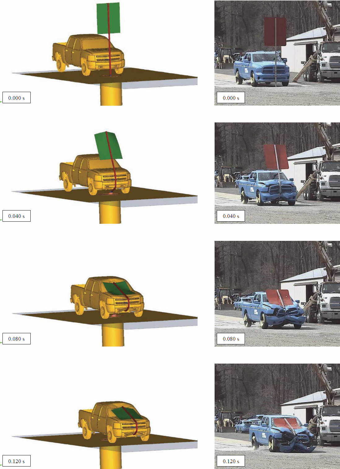
The PSST sign support model details and the simulation setup combined with the vehicle model are shown in Figure 121. Side-by-side comparison plots at different stages of the results are shown in Figures 122 and 123. The figures show the simulation results to be close to the test response; however, the cracking, tearing, and rupture of the roof are not fully captured in the simulation. The research team assumes that, when assessing the system performance, the system would fail the MASH intrusion criteria if one of the corner edges of the sign blank were to contact the vehicle’s roof or windshield.
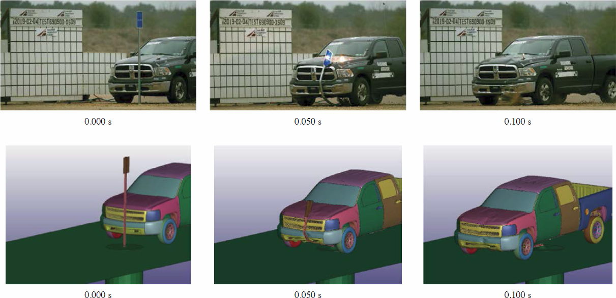
5.2 TTI Test Nos. 690900-XSD 4 Through 690900-XSD 9
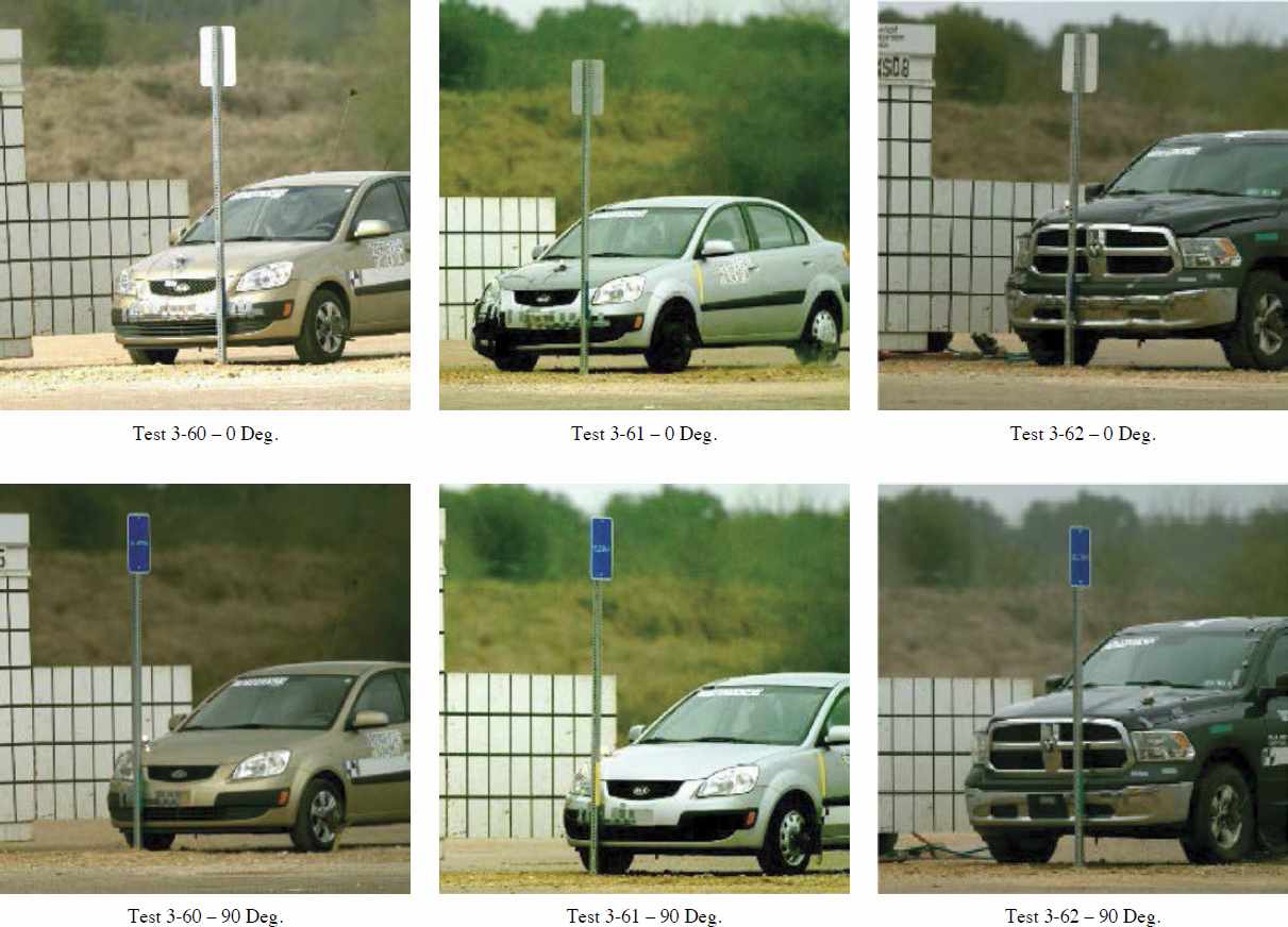
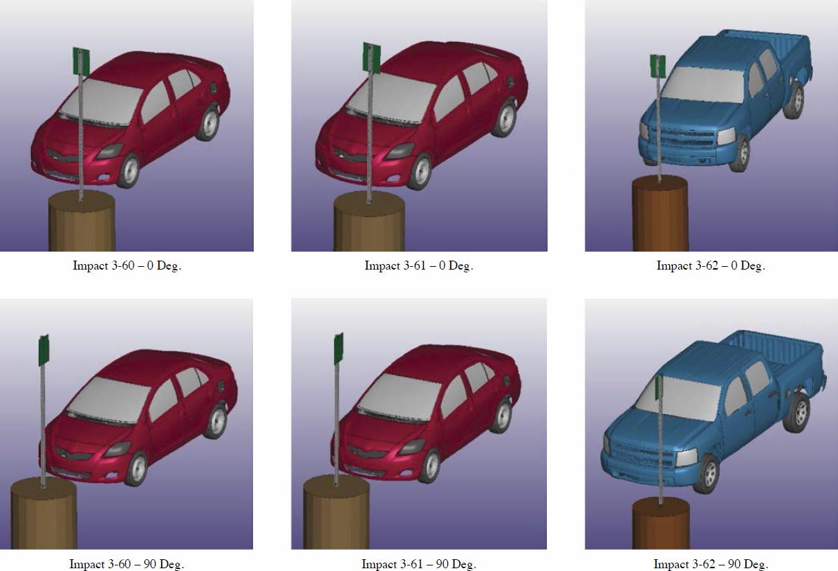
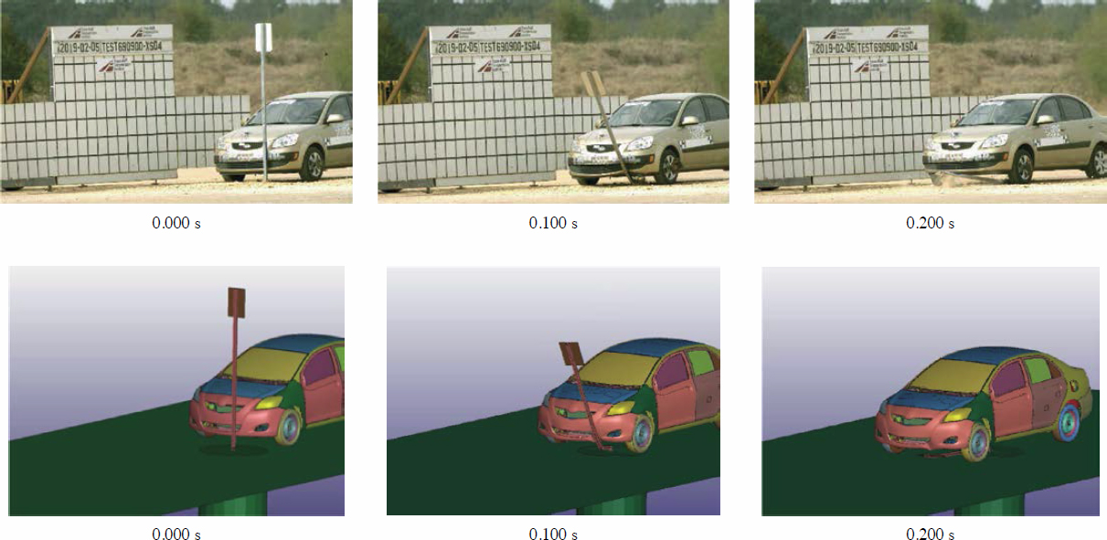
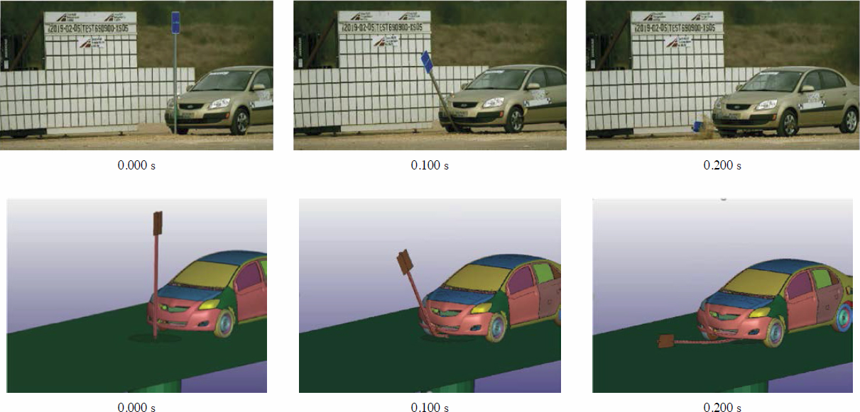
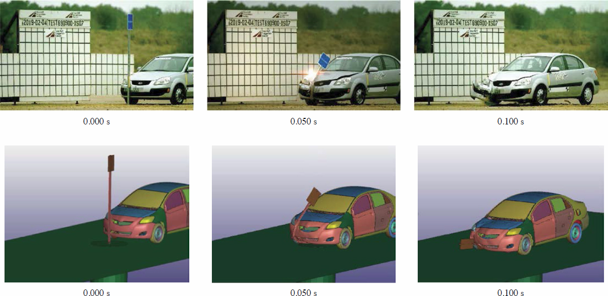
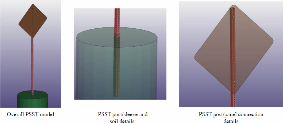
The second series of tests used for the validations was performed on a small PSST sign system at the Texas Transportation Institute (TTI Test Nos. 690900-XSD 4 through 690900-XSD 9). The tested system consisted of a 14-ga., 2-in. PSST post anchored by a 14-ga., 2¼-in. PSST sleeve. The sleeve was embedded 30 in. into the ground and protruded 2 in. above the ground. The post and sleeve overlapped 6 in., and a ⅜-in.-diameter corner bolt was used to connect them. A 12-in. by 18-in. rectangular panel was mounted on the post at a 7-ft mounting height. The panel was made of aluminum and was 0.08 in. thick. The panel was attached to the post using two ⅜-in.-diameter bolts. Six tests were performed on this system: (1) MASH Test No. 3-60 with the sign at 0 degrees relative to the vehicle, (2) MASH Test No. 3-60 with the sign at 90 degrees relative to the vehicle, (3) MASH Test No. 3-61 with the sign at 0 degrees relative to the vehicle, (4) MASH Test No. 3-61 with the sign at 90 degrees relative to the vehicle, (5) MASH Test No. 3-62 with the sign at 0 degrees relative to the vehicle, and (6) MASH Test No. 3-62 with the sign at 90 degrees relative to the vehicle. The impacting vehicles were a MASH 1100C Kia Rio for the first four tests and a MASH 2270P Ram 1500 for the last two tests. Setups from these six tests are shown in Figure 124.
A PSST sign model with this configuration was created and combined with the vehicle models to represent these six test configurations. Computer simulations using these models were performed to assess the model predictions. The model setups are shown in Figure 125. Comparisons between the test and simulation from the six cases are shown in Figures 126 to 131. The figures show very similar behavior between the tests and simulations. The trajectories and impact locations of the sign system relative to the vehicle in all six cases are similar to the full-scale crash tests.


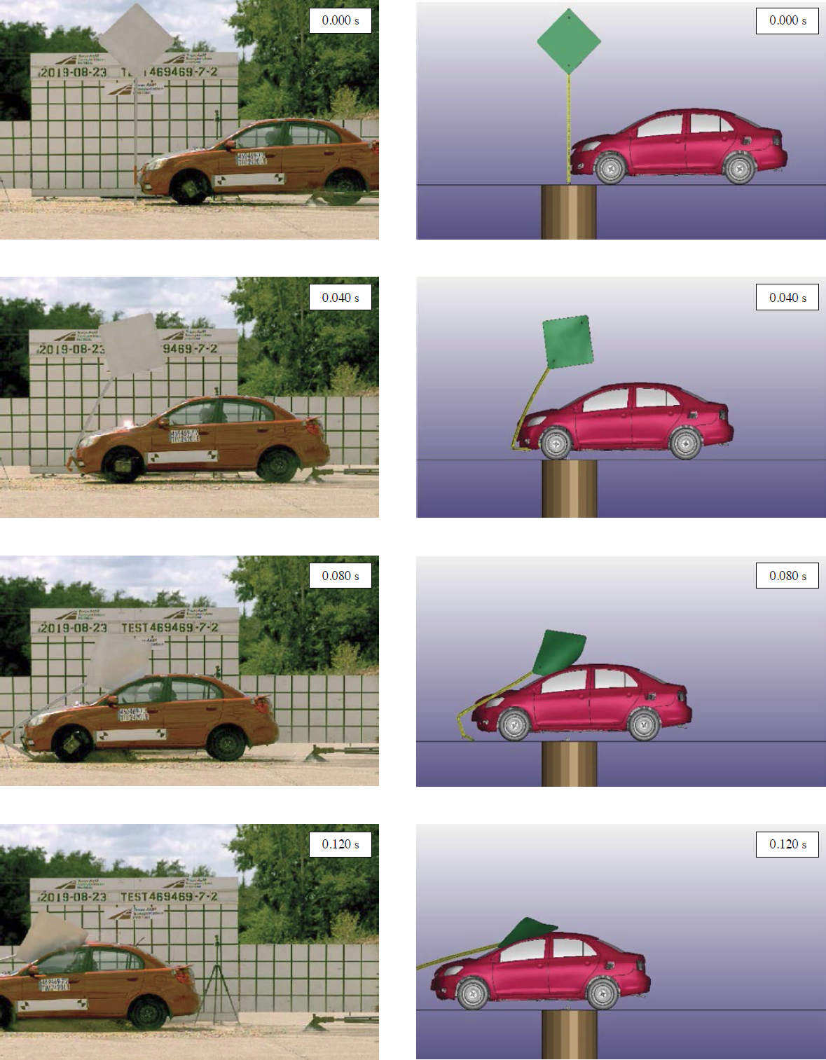
5.3 TTI Test 469469-07-02
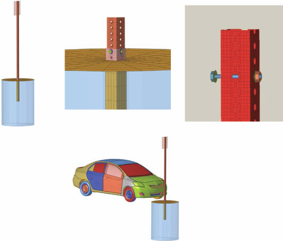
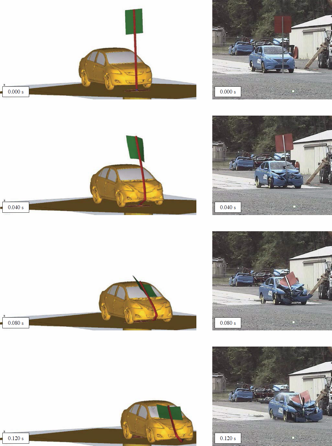
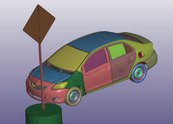
Another test (TTI Test No. 469469-07-02) was used for the PSST model validations (Bligh et al. 2020). The tested system consisted of a 12-ga., 2-in. PSST post anchored by a 2¼-in. PSST sleeve. The sleeve was embedded 36 in. into the ground and protruded 2 in. above ground. The post and sleeve overlapped 9 in., and a ⅜-in.-diameter bolt was used to connect them. A 36-in. by 36-in. diamond-shaped panel was mounted on the post at a 7-ft mounting height. The panel was made of aluminum and was 0.1 in. thick. The panel was attached to the post using two ⅜-in.-diameter bolts. The impacting vehicle was a MASH 1100C Kia Rio. The vehicle impacted the PSST sign support system at a 16-in. offset (¼ vehicle width). The sign was oriented such that the sign panel was aligned with the vehicle’s longitudinal axis (90 degrees).
The vehicle and PSST sign models were set up to represent this test configuration. The PSST sign support model details and the simulation setup are shown in Figures 132 and 133. Side-by-side comparison plots at different stages of the results are shown in Figures 134 and 135. The figures show the simulation results to be close to the test response; however, the cracking, tearing, and rupture of the roof are not fully captured in the simulation. The research team assumes that, when assessing the system performance, the system would fail the MASH intrusion criteria if one of the corner edges of the sign blank were to contact the vehicle’s roof or windshield.
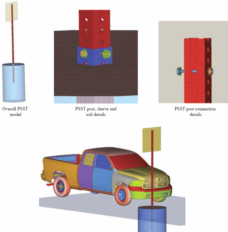
5.4 TTI Test RF476460-1-2-B
The models were used to re-simulate the previous validation tests (under NCHRP Project 03-119) to check that the models would still depict the same test responses. A summary of these efforts is included in the following sections.
The next test used for the validations was performed by TTI (Test No. RF476460-1-2-B) (Bullard et al. 2009). The tested system consisted of a 2-in., 12-gauge PSST and a ⅝-in. thick plywood sign. The plywood sign was attached to the post by two ![]() -in.-diameter Grade 5 bolts. The impacting vehicle was a MASH 2270P vehicle, specifically a Dodge Ram pickup truck. The vehicle impacted the PSST sign support system at a 16-in. offset (¼ vehicle width). A computer model representing this test was created, and iterative simulations were carried out to calibrate the model. The PSST sign support model details and the simulation setup are shown in Figure 136.
-in.-diameter Grade 5 bolts. The impacting vehicle was a MASH 2270P vehicle, specifically a Dodge Ram pickup truck. The vehicle impacted the PSST sign support system at a 16-in. offset (¼ vehicle width). A computer model representing this test was created, and iterative simulations were carried out to calibrate the model. The PSST sign support model details and the simulation setup are shown in Figure 136.


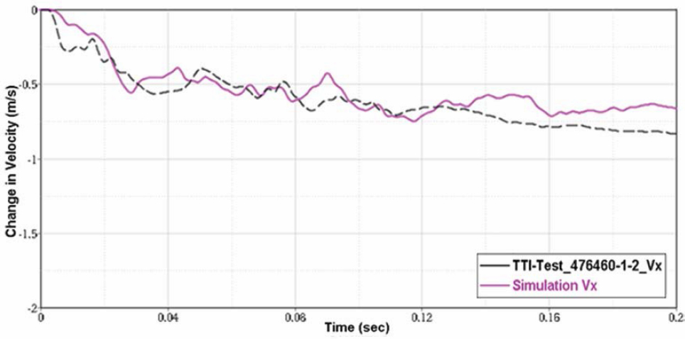
Iterative simulations using this model were carried out, and the results were compared to the full-scale test. Figure 137 shows the change in velocity time history comparison between the test (TTI Test No. RF476460-1-2-B) and the simulation. Side-by-side comparison plots at different stages of the impact are shown in Figure 138. The figures show a very good correlation between the simulation and the test.
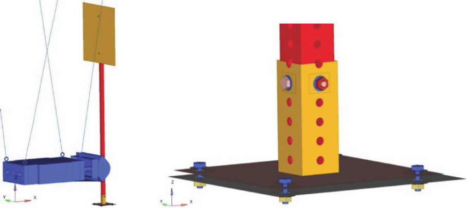
5.5 FOIL Component Test Nos. 19004-A, 19004-B, 19004-C, and 19004-D
The two early tests used for validation were performed at FOIL and involved a 1,183-kg pendulum impacting the PSST sign support systems at two different speeds (10 mph and 24 mph). At each speed, the tests were performed twice to check the repeatability of the results. Additionally, duplicate accelerometers were used for each test (both mounted in the rear of the pendulum) to check the accuracy of the measured accelerations. The acceleration data were used to compute the change of velocity of the pendulum (by integration) and were compared to the simulation results. Computer models that replicate the pendulum test setups were created to validate the
PSST system, as shown in Figure 139. The two simulation setups were identical except for the pendulum’s initial speed.
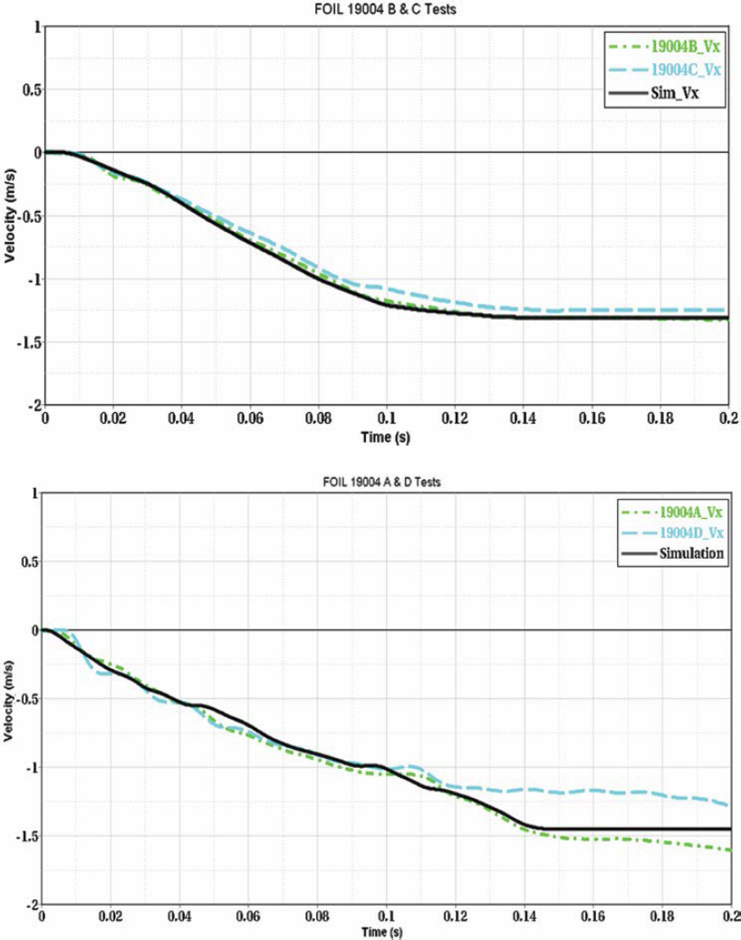
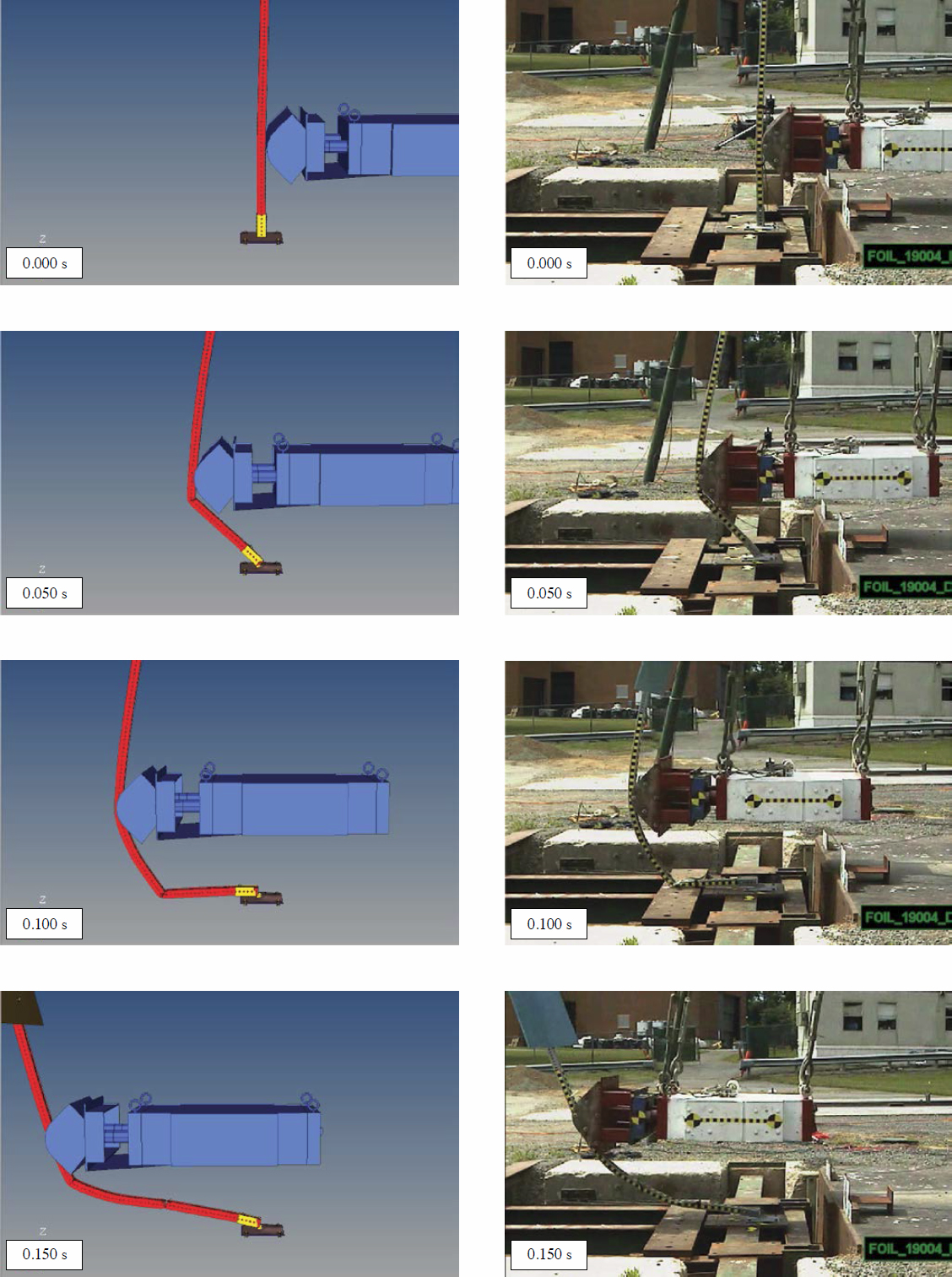
Figure 140 shows the change in velocity time history comparison between the 10-mph pendulum tests (FOIL Test Nos. 19004B and C) and 24-mph pendulum tests (FOIL Test Nos. 19004A and D) and their respective simulations. The figures show a very good correlation between the simulations and tests. Side-by-side comparison plots at different stages of the impact are shown in Figure 141 for the 10-mph impacts and Figure 142 for the 24-mph impacts. The figures show nearly identical PSST sign support system behavior between the tests and simulations.