Guidelines for Evaluating Crashworthiness of Sign Supports and Breakaway Luminaire Poles (2024)
Chapter: 2 Testing Program: Breakaway Luminaire Poles
CHAPTER 2
Testing Program: Breakaway Luminaire Poles
2.1 Overview
In Phase II, based on the simulation results, the poles that indicated concerning behavior in terms of occupant compartment deformation and maximum occupant impact velocity (OIV) were identified. The systems that were recommended for further evaluation with crash testing are listed in Tables 7 and 8. In total, nine full-scale crash tests were recommended. Since the crash testing budget in Phase III was limited, the recommendations were ranked in the order of their importance. This testing plan included nine crash tests on five different critical pole configurations:
- Case No. 101: 50-ft-tall pole with double 4-ft mast arms and weight of 1,100 lb to be tested under MASH Test No. 3-60 with a center impact point and a 0-degree impact angle.
- Case No. 27: 30-ft-tall pole with single 30-ft mast arms and weight of 763 lb to be tested under MASH Test No. 3-60 with a center impact point and a 0-degree impact angle.
- Case No. 59: 20-ft-tall pole with double 15-ft mast arms and weight of 476 lb to be tested under MASH Test No. 3-60 with a center impact point and a 0-degree impact angle.
- Case No. 54: 20-ft-tall pole with double 4-ft mast arms and weight of 374 lb to be tested under MASH Test No. 3-60 with a center impact point and a 25-degree impact angle.
- Case No. 101: 50-ft-tall pole with double 15-ft mast arms and weight of 1,100 lb to be tested under MASH Test No. 3-61 with a center impact point and a 0-degree impact angle.
- Case No. 101: 50-ft-tall pole with double 4-ft mast arms and weight of 1,100 lb to be tested under MASH Test No. 3-62 with a center impact point and a 0-degree impact angle.
- Case No. 59: 20-ft-tall pole with double 15-ft mast arms and weight of 476 lb to be tested under MASH Test No. 3-61 with a center impact point and a 0-degree impact angle.
- Case No. 59: 20-ft-tall pole with double 15-ft mast arms and weight of 476 lb to be tested under MASH Test No. 3-62 with a center impact point and a 0-degree impact angle.
- Case No. 72: 30-ft-tall pole with double 4-ft mast arms and weight of 587 lb to be tested under MASH Test No. 3-62 with a center impact point and a 0-degree impact angle.
The full set of recommended luminaire pole crash tests deemed necessary to validate the simulations and demonstrate the methodology for defining the families of systems could not be conducted with the available funds. After a discussion with the panel, it was decided to continue with running two out of nine full-scale crash tests, specifically the two most critical pole variations supported by the TB1-17 transformer base.
It was noted that without running the full set of nine tests, the simulations (especially for luminaire poles with limited existing crash tests and inconsistency in pole behavior) would not be fully validated, and thus, the MASH testing guidelines for this family might not be fully
defined. Also, the research team might not be able to demonstrate the concept of identifying a family of poles and using a reduced test matrix to determine crashworthiness of that family. Still, the two full-scale crash tests would provide valuable information on the crashworthiness of a family of poles under MASH impact conditions. These test results would also be instrumental for validating simulations and advancing the study.
Conducting three full-scale crash tests on each of the 20 pole configurations shown in this study would require a minimum of 60 tests. The research team, aided by simulation, identified nine critical tests to evaluate pole behavior and determine the accuracy of finite element analysis (FEA). However, only two of these tests were funded. Thus, the research team aimed to maximize the value of these crash tests in understanding pole behavior and providing validation data for further analysis through simulation.
At the completion of Phase II, the following cases were recommended for crash testing:
- Case No. 101: 50-ft-tall pole with dual 4-ft mast arms and approximate weight of 1,100 lb (wall thickness of 0.25 in.) to be tested under MASH Test No. 3-60 with a center impact point and a 0-degree impact angle.
- Case No. 27: 30-ft-tall pole with single 30-ft mast arms and approximate weight of 763 lb (wall thickness of 7 gauge) to be tested under MASH Test No. 3-60 with a center impact point and a 0-degree impact angle.
Considering the immediate needs of state DOTs, which currently use poles with a maximum weight limit of 1,000 lb, and that funds were only available for two tests, a series of impact simulations were conducted on thinner poles to further investigate poles with varied thicknesses. For efficiency, only critical impact conditions (i.e., MASH Test No. 3-60 with the vehicle center impact point) were simulated. The simulation results for thinner poles are shown in Tables 9 and 10.
Based on the simulation results, the first pole selection was changed to Case No. 106L, a 50-ft-tall pole with dual 15-ft mast arms with an approximate weight of 1,000 lb and wall thickness of 7 ga. (0.1880 in.). The second pole selection remained the same. Thus, the following pole configurations were planned to be crash tested:
- Tallest Pole: Case 106L: 50-ft-tall pole with dual 15-ft mast arms and weight of 1,000 lb (wall thickness of 7 gauge) to be tested under MASH Test No. 3-60 with a center impact point and a 0-degree impact angle.
- Longest Arm: Case 27: 30-ft-tall pole with single 30-ft mast arms and weight of 763 lb (wall thickness of 7 gauge) to be tested under MASH Test No. 3-60 with a center impact point and a 0-degree impact angle.
The selection of the impact point was based on the simulation results obtained during Phase II. The analysis indicated that center impacts were more critical than impacts at the right- or left-quarter points. Additionally, an impact angle of 0 degrees was chosen to increase the likelihood of the pole landing on the center of the roof, which has less crush stiffness and would increase the potential for excessive roof crush compared to the stiffened edges. The full-scale vehicle crash tests were evaluated according to MASH 2016 safety criteria.
2.2 Test Requirements and Evaluation Criteria
According to TL-3 of MASH, a breakaway luminaire support system must be subjected to three full-scale crash tests: Test Nos. 3-60, 3-61, and 3-62. MASH Test No. 3-60 is a low-speed impact with a 1100C test vehicle striking the pole at a speed of 19 mph. This test is designed
Table 9. Updated simulation results for thinner pole configurations – maximum occupant compartment deformation (in.).
| Sim. No. | Simulation Round | Pole Height (ft) | Mast Arm Length (ft) | Mast Config. | Thickness (in.) | Pole Weight (lb) | Arm and Connection (lb) | Mass at Ends (lb) | Weight (lb) | MASH 3-60 | MASH 3-61 | MASH 3-62 | |||||||||||||||
|---|---|---|---|---|---|---|---|---|---|---|---|---|---|---|---|---|---|---|---|---|---|---|---|---|---|---|---|
| Left 1/4 | Center | Right 1/4 | Left 1/4 | Center | Right 1/4 | Left 1/4 | Center | Right 1/4 | |||||||||||||||||||
| 0 | 25 | 0 | 25 | 0 | 25 | 0 | 25 | 0 | 25 | 0 | 25 | 0 | 25 | 0 | 25 | 0 | 25 | ||||||||||
| 1 | 1B | 20 | 4 | S | 0.1196 | 143.2 | 40.6 | 75.0 | 258.8 | N/A | N/A | N/A | 1.8 (A) | N/A | N/A | N/A | N/A | N/A | N/A | N/A | N/A | N/A | N/A | N/A | N/A | N/A | N/A |
| 54 | 1B | 20 | 4 | D | 0.1196 | 143.2 | 81.2 | 150.0 | 374.4 | N/A | N/A | 4.5 | 9 | N/A | N/A | N/A | N/A | N/A | N/A | N/A | N/A | N/A | N/A | N/A | N/A | N/A | N/A |
| 6 | 2A | 20 | 15 | S | 0.1196 | 143.2 | 86.8 | 75.0 | 305.0 | N/A | N/A | 4.3 | 9.1 | N/A | N/A | N/A | N/A | N/A | N/A | N/A | N/A | N/A | N/A | N/A | N/A | N/A | N/A |
| 59 | 1B | 20 | 15 | D | 0.1196 | 143.2 | 173.6 | 150.0 | 466.8 | N/A | 0.8 | 6.9 | 4.1 | N/A | N/A | N/A | N/A | N/A | N/A | N/A | N/A | N/A | N/A | N/A | N/A | N/A | N/A |
| 9 | 1B | 20 | 30 | S | 0.1880 | 143.2 | 212.0 | 75.0 | 552.3 | N/A | N/A | 7.5 | 9.5 | 1.9 (A) | N/A | N/A | N/A | N/A | N/A | N/A | N/A | N/A | N/A | N/A | N/A | N/A | N/A |
| 19L | 2A | 30 | 4 | S | 0.1196 | 225.4 | 40.6 | 75.0 | 341.0 | 2.5 | 1.7 | ||||||||||||||||
| 72L | 2A | 30 | 4 | D | 0.1196 | 225.4 | 81.2 | 150.0 | 456.6 | 2.4 | 3.6 | ||||||||||||||||
| 24L | 2A | 30 | 15 | S | 0.1196 | 225.4 | 86.8 | 75.0 | 387.2 | 7.9 | 7.1 | ||||||||||||||||
| 77L | 2A | 30 | 15 | D | 0.1196 | 225.4 | 173.6 | 150.0 | 549.0 | 4.3 | N/A | ||||||||||||||||
| 27L | 2A | 30 | 30 | S | 0.1196 | 225.4 | 212.0 | 75.0 | 512.4 | 5 | 6.3 | ||||||||||||||||
| 19 | 2A | 30 | 4 | S | 0.1880 | 355.7 | 40.6 | 75.0 | 471.3 | N/A | N/A | 2.6 | 4.7 | N/A | N/A | N/A | N/A | N/A | N/A | N/A | N/A | N/A | N/A | N/A | N/A | N/A | N/A |
| 72 | 2A | 30 | 4 | D | 0.1880 | 355.7 | 81.2 | 150.0 | 586.9 | N/A | N/A | 4.4 | 4.8 | N/A | N/A | N/A | N/A | N/A | N/A | N/A | N/A | N/A | N/A | N/A | N/A | N/A | N/A |
| 24 | 2A | 30 | 15 | S | 0.1880 | 355.7 | 86.8 | 75.0 | 517.6 | N/A | N/A | 7.5 | 9.4 | N/A | N/A | N/A | N/A | N/A | N/A | N/A | N/A | N/A | N/A | N/A | N/A | N/A | N/A |
| 77 | 2A | 30 | 15 | D | 0.1880 | 355.7 | 173.6 | 150.0 | 679.3 | N/A | 2.4 | 2.7 | N/A | N/A | N/A | N/A | N/A | N/A | N/A | N/A | N/A | N/A | N/A | N/A | N/A | N/A | N/A |
| 27 | 2A | 30 | 30 | S | 0.1880 | 355.7 | 212.0 | 75.0 | 763.3 | 2.4 (C) | N/A | 9.7 | 9.3 | 6.2 (A) | N/A | N/A | N/A | N/A | N/A | N/A | N/A | N/A | N/A | N/A | N/A | N/A | N/A |
| 35L | 2A | 40 | 4 | S | 0.1880 | 367.4 | 40.6 | 75.0 | 483.0 | 3.4 | 2.6 | ||||||||||||||||
| 88L | 2A | 40 | 4 | D | 0.1880 | 367.4 | 81.2 | 150.0 | 598.6 | 2.9 | 2 | ||||||||||||||||
| 40L | 2A | 40 | 15 | S | 0.1880 | 367.4 | 86.8 | 75.0 | 529.2 | 2.5 | 3.7 | ||||||||||||||||
| 93L | 2A | 40 | 15 | D | 0.1880 | 367.4 | 173.6 | 150.0 | 691.0 | 5.1 | 2.5 | ||||||||||||||||
| 41L | 2A | 40 | 20 | S | 0.1880 | 367.4 | 151.5 | 75.0 | 593.9 | 1.5 | 5.1 | ||||||||||||||||
| 94L | 2A | 40 | 20 | D | 0.1880 | 367.4 | 303.0 | 150.0 | 820.4 | 2.9 | N/A | ||||||||||||||||
| 35 | 2A | 40 | 4 | S | 0.1880 | 578.8 | 40.6 | 75.0 | 694.4 | N/A | N/A | 4.3 | 4.5 | N/A | N/A | N/A | N/A | N/A | N/A | N/A | N/A | N/A | N/A | N/A | N/A | N/A | N/A |
| 88 | 2A | 40 | 4 | D | 0.1880 | 578.8 | 81.2 | 150.0 | 810.0 | N/A | 1.8 (A) | 6 | 6 | N/A | N/A | N/A | N/A | N/A | N/A | N/A | N/A | N/A | N/A | N/A | N/A | N/A | N/A |
| 40 | 2A | 40 | 15 | S | 0.1880 | 578.8 | 86.8 | 75.0 | 740.6 | N/A | N/A | 10.2 | 4.5 | N/A | N/A | N/A | N/A | N/A | N/A | N/A | N/A | N/A | N/A | N/A | N/A | N/A | N/A |
| 93 | 2A | 40 | 15 | D | 0.1880 | 578.8 | 173.6 | 150.0 | 902.4 | N/A | 1.1 (A) | 7.2 | 4.4 | N/A | N/A | N/A | N/A | N/A | N/A | N/A | N/A | N/A | N/A | N/A | N/A | N/A | N/A |
| 41 | 2A | 40 | 20 | S | 0.1880 | 578.8 | 151.5 | 75.0 | 805.3 | 3.7 (C) | 6 | 11 | 7.9 | N/A | N/A | N/A | N/A | N/A | N/A | N/A | N/A | N/A | N/A | N/A | N/A | N/A | N/A |
| 94 | 2A | 40 | 20 | D | 0.1880 | 578.8 | 303.0 | 150.0 | 1,031.8 | 3.7 (A) | N/A | 13.5 | N/A | N/A | N/A | N/A | N/A | N/A | N/A | N/A | N/A | N/A | N/A | N/A | N/A | N/A | |
| 48L | 1B | 50 | 4 | S | 0.1880 | 652.1 | 40.6 | 75.0 | 767.7 | 0.8 | 6.1 | ||||||||||||||||
| 101L | 1B | 50 | 4 | D | 0.1880 | 652.1 | 81.2 | 150.0 | 883.3 | 10.4 | 8.4 | ||||||||||||||||
| 53L | 1B | 50 | 15 | S | 0.1880 | 652.1 | 86.8 | 75.0 | 814.0 | 7.2 | 6.5 | ||||||||||||||||
| 106L | 1B | 50 | 15 | D | 0.1880 | 652.1 | 173.6 | 150.0 | 975.7 | 7.7 | 5.1 | ||||||||||||||||
| 48 | 1B | 50 | 4 | S | 0.2500 | 868.6 | 40.6 | 75.0 | 984.2 | N/A | N/A | 14.8 | 9.8 | N/A | N/A | N/A | N/A | N/A | N/A | N/A | N/A | N/A | N/A | N/A | N/A | N/A | N/A |
| 101 | 1B | 50 | 4 | D | 0.2500 | 868.6 | 81.2 | 150.0 | 1,099.8 | N/A | N/A | 15.8 | 10.3 | N/A | N/A | N/A | N/A | N/A | N/A | N/A | N/A | N/A | N/A | N/A | N/A | N/A | N/A |
| 53 | 1B | 50 | 15 | S | 0.2500 | 868.6 | 86.8 | 75.0 | 1,030.4 | N/A | N/A | 10 | 14 | N/A | N/A | N/A | N/A | N/A | N/A | N/A | N/A | N/A | N/A | N/A | N/A | 2.8 | 10 |
| 106 | 1B | 50 | 15 | D | 0.2500 | 868.6 | 173.6 | 150.0 | 1,192.2 | N/A | 8.5 | 14.3 | 8 | N/A | N/A | N/A | N/A | N/A | N/A | N/A | N/A | N/A | N/A | N/A | N/A | N/A | N/A |
Notes: ![]() = low potential to pass MASH (deformation > 4.0 in.);
= low potential to pass MASH (deformation > 4.0 in.); ![]() = medium potential to pass MASH (0.0 in. < deformation ≤ 4.0 in.); “A,” “B,” “C” and “W” stand for A-pillar, B-pillar, C-pillar, and windshield deformation; “N/A” indicates that pole did not contact any part of vehicle.
= medium potential to pass MASH (0.0 in. < deformation ≤ 4.0 in.); “A,” “B,” “C” and “W” stand for A-pillar, B-pillar, C-pillar, and windshield deformation; “N/A” indicates that pole did not contact any part of vehicle.
Table 10. Updated simulation results for thinner pole configurations – longitudinal OIV (ft/s).
| Sim. No. | Simula on Round | Pole Height (ft) | Mast Arm Length (ft) | Mast Config. | Thickness (in.) | Pole Weight (lb) | Arm Connec on (lb) | Mass at Ends (lb) | Weight (lb) | MASH 3-60 | MASH 3-61 | MASH 3-62 | |||||||||||||||
|---|---|---|---|---|---|---|---|---|---|---|---|---|---|---|---|---|---|---|---|---|---|---|---|---|---|---|---|
| Le 1/4 | Center | Right 1/4 | Le 1/4 | Center | Right 1/4 | Le 1/4 | Center | Right 1/4 | |||||||||||||||||||
| 0 | 25 | 0 | 25 | 0 | 25 | 0 | 25 | 0 | 25 | 0 | 25 | 0 | 25 | 0 | 25 | 0 | 25 | ||||||||||
| 1 | 1B | 20 | 4 | S | 0.1196 | 143.2 | 40.6 | 75.0 | 258.8 | 4.2 | 4.3 | 10.7 | 8.7 | 4.5 | 11.7 | 9.8 | 9.8 | 10.0 | 10.0 | 9.8 | 10.2 | 4.1 | 4.3 | 4.4 | 4.3 | 4.1 | 4.1 |
| 54 | 1B | 20 | 4 | D | 0.1196 | 143.2 | 81.2 | 150.0 | 374.4 | 4.5 | 4.1 | 10.8 | 8.7 | 4.4 | 12.5 | 9.9 | 9.9 | 10.3 | 10.0 | 9.7 | 10.3 | 4.0 | 4.2 | 4.6 | 4.4 | 3.9 | 4.0 |
| 6 | 2A | 20 | 15 | S | 0.1196 | 143.2 | 86.8 | 75.0 | 305.0 | 5.3 | 4.8 | 10.9 | 9 | 6.7 | 13.3 | 10.0 | 9.9 | 10.0 | 10.0 | 9.7 | 10.4 | 3.8 | 4.2 | 4.6 | 4.4 | 3.9 | 4.0 |
| 59 | 1B | 20 | 15 | D | 0.1196 | 143.2 | 173.6 | 150.0 | 466.8 | 7.2 | 4.8 | 10.9 | 8.6 | 4.8 | 9.6 | 10.0 | 10.1 | 10.2 | 10.1 | 10.0 | 10.2 | 4.0 | 4.2 | 4.6 | 4.6 | 4.3 | 4.1 |
| 9 | 1B | 20 | 30 | S | 0.1880 | 143.2 | 212.0 | 75.0 | 552.3 | 12.4 | 6.0 | 15.9 | 9.2 | 6.0 | 8.7 | 10.5 | 10.5 | 11.1 | 11.2 | 10.5 | 10.8 | 4.7 | 5.1 | 5.3 | 5.8 | 4.6 | 4.8 |
| 19L | 2A | 30 | 4 | S | 0.1196 | 225.4 | 40.6 | 75.0 | 341.0 | 10.5 | 9 | ||||||||||||||||
| 72L | 2A | 30 | 4 | D | 0.1196 | 225.4 | 81.2 | 150.0 | 456.6 | 10.4 | 8.5 | ||||||||||||||||
| 24L | 2A | 30 | 15 | S | 0.1196 | 225.4 | 86.8 | 75.0 | 387.2 | 10.7 | 8.9 | ||||||||||||||||
| 77L | 2A | 30 | 15 | D | 0.1196 | 225.4 | 173.6 | 150.0 | 549.0 | 11.4 | 8.7 | ||||||||||||||||
| 27L | 2A | 30 | 30 | S | 0.1196 | 225.4 | 212.0 | 75.0 | 512.4 | 12.3 | 9.5 | ||||||||||||||||
| 19 | 2A | 30 | 4 | S | 0.1880 | 355.7 | 40.6 | 75.0 | 471.3 | 11 | 5.0 | 10.9 | 9.3 | 11.2 | 13.0 | 11.2 | 11.2 | 12.0 | 12.0 | 11.5 | 11.9 | 5.1 | 5.7 | 5.9 | 6.2 | 5.4 | 5.2 |
| 72 | 2A | 30 | 4 | D | 0.1880 | 355.7 | 81.2 | 150.0 | 586.9 | 11.6 | 5.0 | 12.1 | 9.1 | 12.5 | 12.4 | 11.3 | 11.3 | 11.6 | 11.6 | 11.5 | 11.6 | 5.7 | 5.8 | 6.0 | 6.4 | 5.4 | 5.2 |
| 24 | 2A | 30 | 15 | S | 0.1880 | 355.7 | 86.8 | 75.0 | 517.6 | 10.8 | 5.0 | 10.8 | 9.4 | 11.5 | 13.2 | 10.8 | 11.3 | 11.8 | 11.5 | 11.4 | 11.7 | 5.2 | 5.4 | 5.9 | 6.2 | 5.4 | 5.1 |
| 77 | 2A | 30 | 15 | D | 0.1880 | 355.7 | 173.6 | 150.0 | 679.3 | 11.3 | 5.1 | 10.6 | 8.9 | 10.9 | 13.1 | 11.5 | 11.5 | 12.5 | 11.7 | 10.5 | 11.5 | 5.6 | 5.5 | 6.0 | 6.4 | 5.4 | 5.3 |
| 27 | 2A | 30 | 30 | S | 0.1880 | 355.7 | 212.0 | 75.0 | 763.3 | 11.3 | 5.7 | 15.6 | 10.0 | 11.6 | 12.0 | 12.6 | 11.9 | 12.6 | 12.2 | 12.6 | 12.4 | 5.9 | 6.0 | 6.3 | 6.5 | 6.1 | 6.1 |
| 35L | 2A | 40 | 4 | S | 0.1880 | 367.4 | 40.6 | 75.0 | 483.0 | 10.6 | 8.8 | ||||||||||||||||
| 88L | 2A | 40 | 4 | D | 0.1880 | 367.4 | 81.2 | 150.0 | 598.6 | 11.1 | 9.0 | ||||||||||||||||
| 40L | 2A | 40 | 15 | S | 0.1880 | 367.4 | 86.8 | 75.0 | 529.2 | 10.7 | 9.0 | ||||||||||||||||
| 93L | 2A | 40 | 15 | D | 0.1880 | 367.4 | 173.6 | 150.0 | 691.0 | 10.8 | 10.8 | ||||||||||||||||
| 41L | 2A | 40 | 20 | S | 0.1880 | 367.4 | 151.5 | 75.0 | 593.9 | 10.8 | 9.4 | ||||||||||||||||
| 94L | 2A | 40 | 20 | D | 0.1880 | 367.4 | 303.0 | 150.0 | 820.4 | 10.8 | 2.9 | ||||||||||||||||
| 35 | 2A | 40 | 4 | S | 0.1880 | 578.8 | 40.6 | 75.0 | 694.4 | 9.3 | 5.5 | 11.0 | 9.5 | 11.3 | 12.4 | 12.4 | 12.7 | 13.0 | 13.3 | 13.6 | 13.4 | 6.1 | 7.1 | 7.4 | 7.5 | 6.2 | 6.5 |
| 88 | 2A | 40 | 4 | D | 0.1880 | 578.8 | 81.2 | 150.0 | 810.0 | 9.9 | 6.3 | 12.3 | 9.8 | 11.3 | 12.3 | 13.8 | 13.3 | 13.7 | 13.4 | 13.7 | 13.3 | 6.5 | 6.5 | 7.6 | 7.7 | 7.3 | 6.4 |
| 40 | 2A | 40 | 15 | S | 0.1880 | 578.8 | 86.8 | 75.0 | 740.6 | 9.3 | 5.7 | 15.6 | 9.4 | 12.0 | 12.0 | 13.0 | 12.8 | 13.2 | 12.6 | 13.2 | 12.9 | 6.5 | 6.5 | 7.3 | 7.4 | 6.6 | 6.4 |
| 93 | 2A | 40 | 15 | D | 0.1880 | 578.8 | 173.6 | 150.0 | 902.4 | 11.7 | 6.6 | 11.6 | 9.9 | 11.2 | 14.0 | 12.8 | 12.8 | 13.0 | 13.2 | 13.2 | 13.0 | 7.0 | 6.8 | 7.8 | 7.7 | 7.2 | 6.9 |
| 41 | 2A | 40 | 20 | S | 0.1880 | 578.8 | 151.5 | 75.0 | 805.3 | 10.6 | 5.9 | 14.8 | 9.9 | 12.3 | 12.0 | 13.1 | 12.9 | 13.0 | 12.9 | 13.2 | 13.3 | 6.7 | 6.7 | 7.5 | 7.7 | 6.9 | 6.4 |
| 94 | 2A | 40 | 20 | D | 0.1880 | 578.8 | 303.0 | 150.0 | 1,031.8 | 10.1 | 6.2 | 15.1 | 10.1 | 11.3 | 12.2 | 14.4 | 13.4 | 13.8 | 13.5 | 14.0 | 13.2 | 7.3 | 6.7 | 7.8 | 7.8 | 7.4 | 6.8 |
| 48L | 1B | 50 | 4 | S | 0.1880 | 652.1 | 40.6 | 75.0 | 767.7 | 12.7 | 10.3 | ||||||||||||||||
| 101L | 1B | 50 | 4 | D | 0.1880 | 652.1 | 81.2 | 150.0 | 883.3 | 15.4 | 10.3 | ||||||||||||||||
| 53L | 1B | 50 | 15 | S | 0.1880 | 652.1 | 86.8 | 75.0 | 814.0 | 15.2 | 10.3 | ||||||||||||||||
| 106L | 1B | 50 | 15 | D | 0.1880 | 652.1 | 173.6 | 150.0 | 975.7 | 12.6 | 10 | ||||||||||||||||
| 48 | 1B | 50 | 4 | S | 0.2500 | 868.6 | 40.6 | 75.0 | 984.2 | 6.6 | 6.5 | 15.3 | 10.9 | 11.4 | 14.6 | 13.6 | 14.3 | 14.7 | 14.4 | 14.1 | 14.3 | 7.9 | 8.6 | 9.5 | 9.2 | 8.1 | 8.7 |
| 101 | 1B | 50 | 4 | D | 0.2500 | 868.6 | 81.2 | 150.0 | 1,099.8 | 7.1 | 6.7 | 15.7 | 10.7 | 8.2 | 12.4 | 14.7 | 14.4 | 14.5 | 14.2 | 13.9 | 14.8 | 8.4 | 8.9 | 9.5 | 9.5 | 8.5 | 9.0 |
| 53 | 1B | 50 | 15 | S | 0.2500 | 868.6 | 86.8 | 75.0 | 1,030.4 | 8.8 | 7.4 | 15.2 | 11.0 | 11.8 | 13.2 | 13.7 | 14.5 | 14.6 | 14.3 | 13.6 | 14.7 | 8.7 | 8.9 | 9.5 | 9.3 | 8.8 | 8.9 |
| 106 | 1B | 50 | 15 | D | 0.2500 | 868.6 | 173.6 | 150.0 | 1,192.2 | 7.4 | 7.3 | 15.2 | 10.8 | 8.6 | 11.7 | 14.0 | 14.2 | 14.6 | 14.0 | 13.8 | 14.5 | 8.7 | 9.4 | 9.4 | 9.6 | 8.7 | 8.9 |
Notes: ![]() = low potential to pass MASH;
= low potential to pass MASH; ![]() = medium potential to pass MASH; S = single mast arm; D = dual mast arms.
= medium potential to pass MASH; S = single mast arm; D = dual mast arms.
to evaluate the kinetic energy required to activate the breakaway mechanism in the support system, which is the TB1-17 transformer base for the current case. The primary concern for this low-speed test is the potential for excessive change in velocity and occupant compartment intrusion. MASH Test Nos. 3-61 and 3-62 are intended to evaluate the behavior of the luminaire pole system under high-speed impacts. The primary concerns for these tests are intrusion of the pole system components into the vehicle’s windshield, roof, and rear window, the potential for vehicle instability, and elevated occupant risk measures, including OIV and occupant ride-down acceleration (ORA).
MASH recommends a critical impact point be determined that represents the worst-case impact conditions that would be consistent with the manner in which the luminaire system will be deployed. Safety features, such as for a luminaire pole used along the outside of divided highways, need only be evaluated for impact angles from 0 to 25 degrees. For the current study, Test Nos. 3-60, 3-61, and 3-62 were evaluated on luminaire pole configurations for impact angles of 0 and 25 degrees.
Moreover, MASH recommends that single support structures be tested with the centerline of the support aligned with the left-front or right-front quarter point of the impacting vehicle to promote vehicle instability. However, as described in Interim Report No. 1, some past crash testing and simulation efforts have revealed impact scenarios where a particular quarter point may be more critical than the other quarter point, or the center point would be more critical than the left or right quarter points (Asadollahi Pajouh et al. 2021). In this study, all pole configurations were simulated and evaluated with the center of the pole aligned with the left-quarter, center, and right-quarter points of the impacting vehicle. Thus, each pole configuration needed to be evaluated under 18 impact conditions in total, as summarized in Table 11. In addition to the standard occupant risk measures, the post-impact head deceleration (PHD), the theoretical head impact velocity (THIV), and the Acceleration Severity Index (ASI) were determined and reported. Additional discussion on PHD, THIV, and ASI is provided in MASH 2016.
Evaluation criteria for full-scale vehicle crash testing are based on three appraisal areas: (1) structural adequacy, (2) occupant risk, and (3) vehicle trajectory after the collision. Criteria for structural adequacy are intended to check whether the test article readily activates in a predictable manner by breaking away, fracturing, or yielding after a vehicle impact. Occupant risk evaluates the degree of hazard to occupants in the impacting vehicle. Post-impact vehicle trajectory is a measure of the potential of the vehicle to result in a secondary collision with other vehicles or fixed objects, thereby increasing the risk of injury to the occupants of the impacting vehicle or other vehicles. These evaluation criteria are summarized in Table 12 and defined in greater detail in MASH.
Table 11. MASH test matrices for breakaway luminaire supports.
| Test Article | Test Designation No. | Test Vehicle | Vehicle Weight (lb) | Impact Conditions | Impact Point | Evaluation Criteria1 | |
|---|---|---|---|---|---|---|---|
| Speed (mph) | Angle (deg.) | ||||||
| Luminaire Support Structures | 3-60 | 1100C | 2,425 | 19 | 0–25 | left ¼, center, right ¼ | B, D, F, H, I, N |
| 3-61 | 1100C | 2,425 | 62 | 0–25 | left ¼, center, right ¼ | B, D, F, H, I, N | |
| 3-62 | 2270P | 5,000 | 62 | 0–25 | left ¼, center, right ¼ | B, D, F, H, I, N | |
Table 12. MASH evaluation criteria for support structures (AASHTO 2016).
| Structural Adequacy | B. | Test article should readily activate in a predictable manner by breaking away, fracturing, or yield. | ||
| Occupant Risk | D. | Detached elements, fragments, or other debris from the test article should not penetrate or show potential for penetrating the occupant compartment, or present an undue hazard to other traffic, pedestrians, or personnel in a work zone. Deformations of, or intrusions into, the occupant compartment should not exceed limits set forth in Section 5.2.2 and Appendix E of MASH 2016. | ||
| F. | The vehicle should remain upright during and after collision. The maximum roll and pitch angles are not to exceed 75 degrees. | |||
| H. | OIV (see Appendix A, Section A5.2.2 of MASH 2016 for calculation procedure) should satisfy the following limits: | |||
| OIV Limits | ||||
| Component | Preferred | Maximum | ||
| Longitudinal | 10 ft/s (3.0 m/s) | 16 ft/s (4.9 m/s) | ||
| I. | ORA (see Appendix A, Section A5.2.2 of MASH 2016 for calculation procedure) should satisfy the following limits: | |||
| ORA Limits | ||||
| Component | Preferred | Maximum | ||
| Longitudinal and lateral | 15.0 g | 20.49 g | ||
| Post-Impact Vehicular Response | N. Vehicle trajectory behind the test article is acceptable. | |||
2.3 Design Details
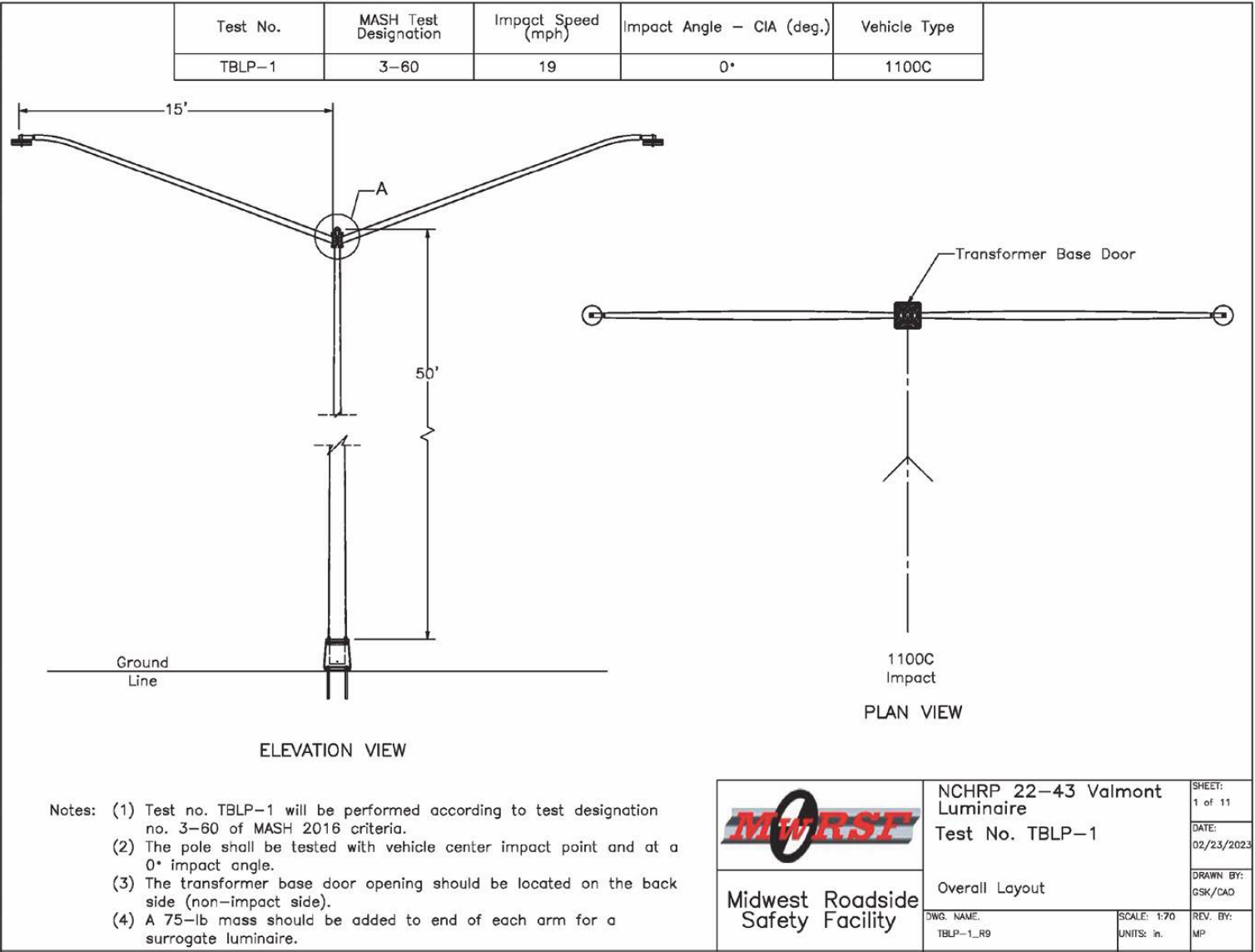
2.3.1 Test No. TBLP-1
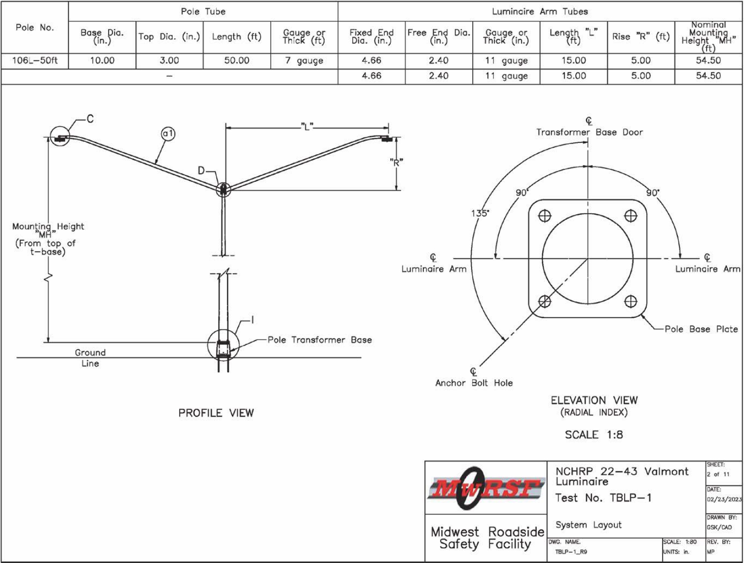
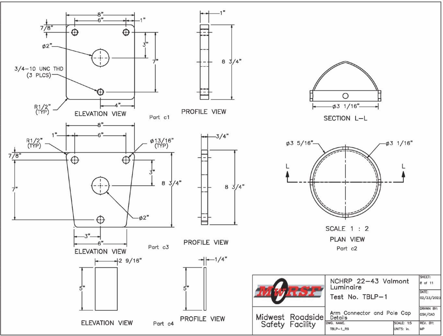
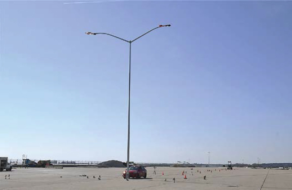
In this test, a 50-ft-tall pole with dual 15-ft mast arms mounted on the TB1-17 transformer base was crash tested under MASH Test No. 3-60. The breakaway luminaire pole and transformer base details are shown in Figures 1 through 11, and photographs of the system are shown in Figures 12 through 15. Material specifications, mill certifications, and certificates of conformity for the system materials are shown in Appendix A.
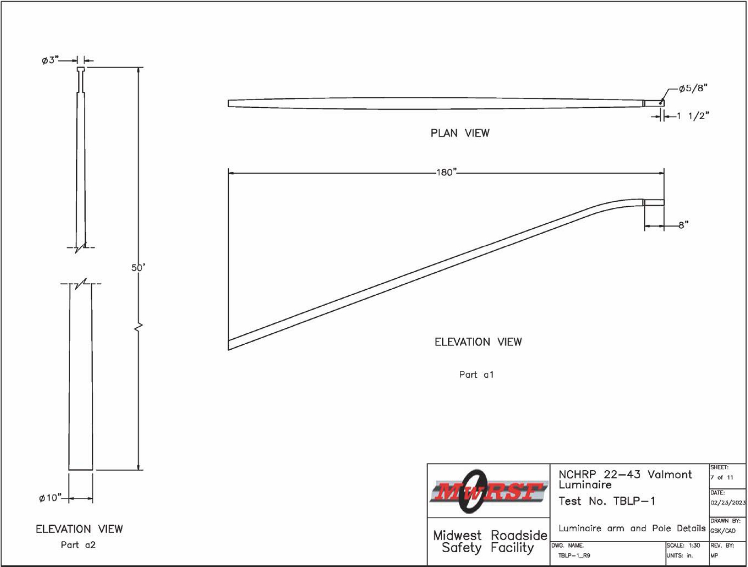
The luminaire pole had a diameter of 10 in. at the base, tapering to 3 in. at the top, with a 7-gauge wall thickness. The steel luminaire pole was manufactured to ASTM A595 Grade A and was hot-dip galvanized in accordance with ASTM A123. Note that the luminaire pole received from Valmont did not have the hand-hole opening. The luminaire pole had a maximum mounting height of 54 ft 6 in. from the top of the mast arms to the top of the pole base. The height to the top of the luminaire pole (excluding rain cap) was 51 ft 6 in. from the ground.
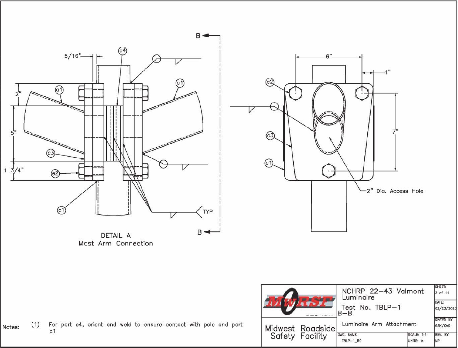
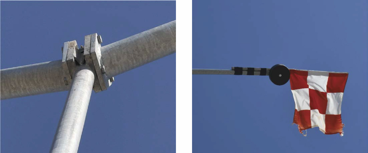
The two 11-gauge mast arms were attached to the pole 6 in. below the top of the luminaire pole. The mast arms extended outward 15 ft from the face of the luminaire pole and 5 ft upward above the top of the luminaire pole. The two mast arms extended outward perpendicular to the direction of the impact. A 75-lb mass was added to the end of each arm as a surrogate luminaire. The total weight of the structure (i.e., pole, mast arms, connections, surrogate luminaires, and base plate) was 1,015 lb.
An attachment simplex with three ¾-in.-diameter A153 galvanized hex bolts was used to connect each mast arm to the luminaire pole. The attachment simplex consisted of a 1-in.-thick ASTM A36 steel plate on the pole side and a ¾-in.-thick ASTM A36 steel plate on the mast arm side, as shown in Figure 3. The bottom of the pole was welded to a 1¼-in.-thick, 13.13-in.-square steel base plate. The mast arms were made of ASTM A595 Grade A steel.
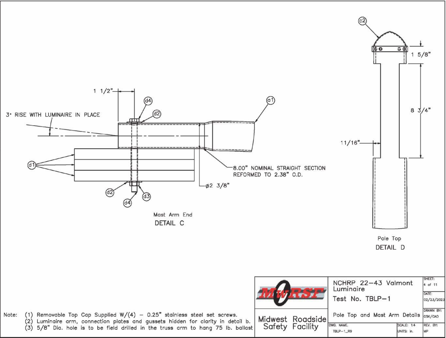
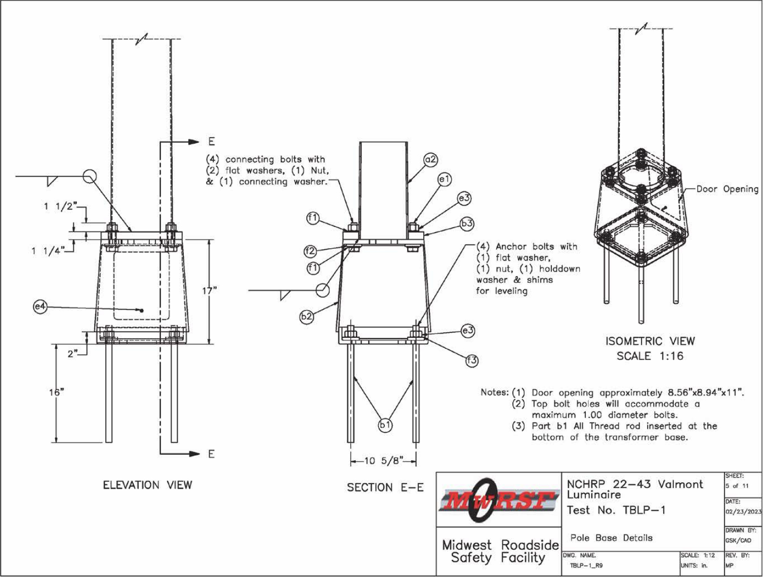
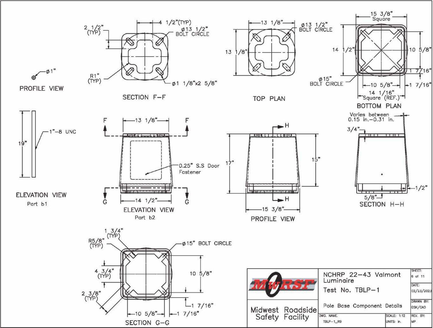
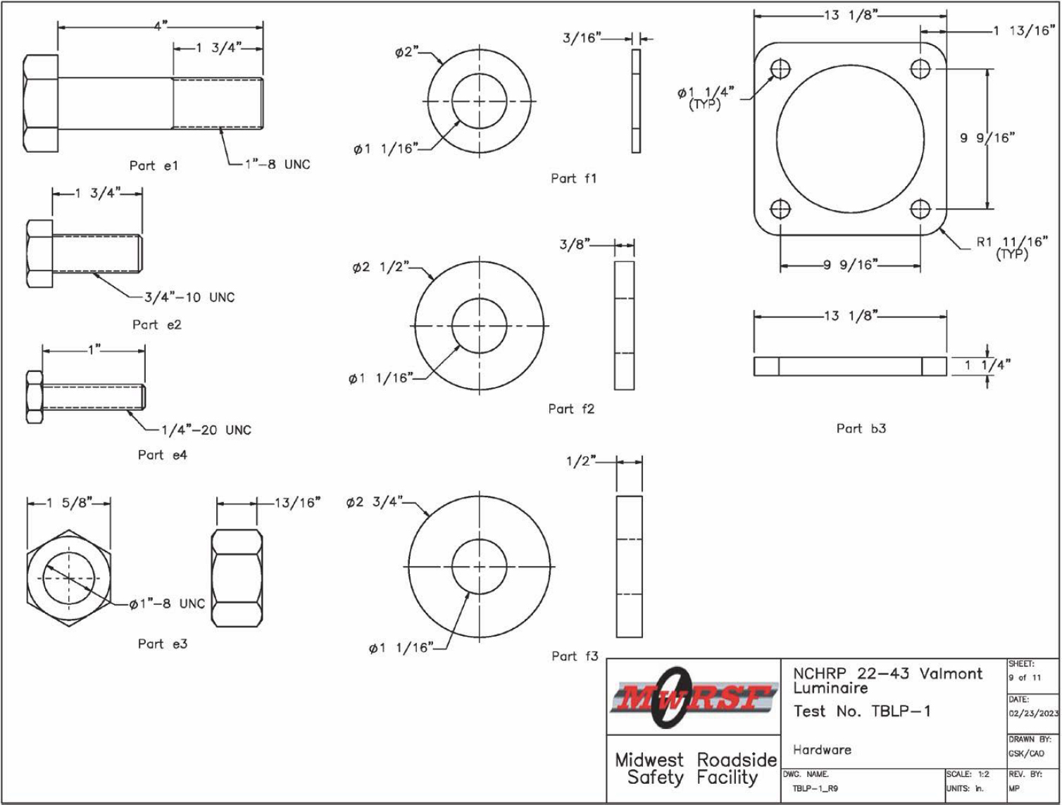
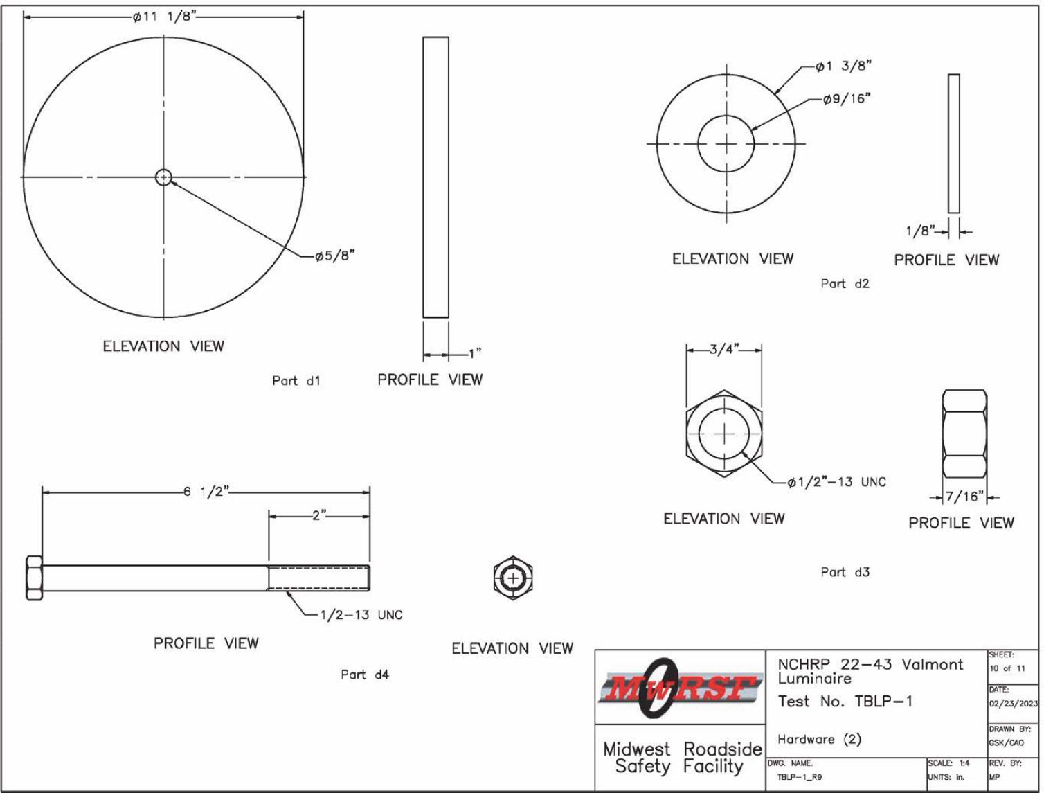

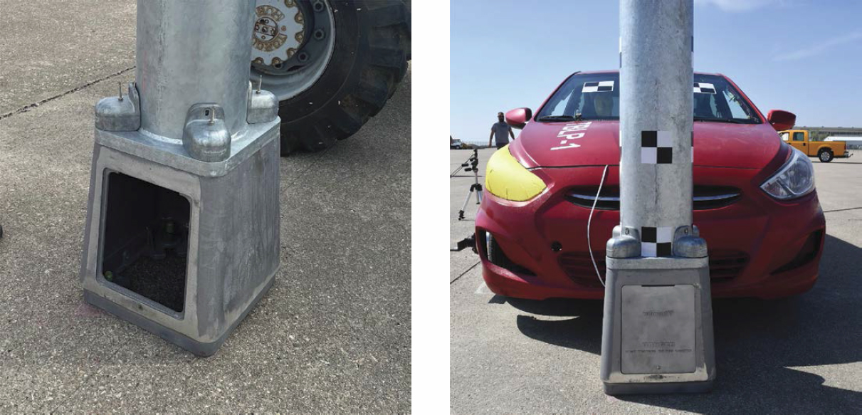
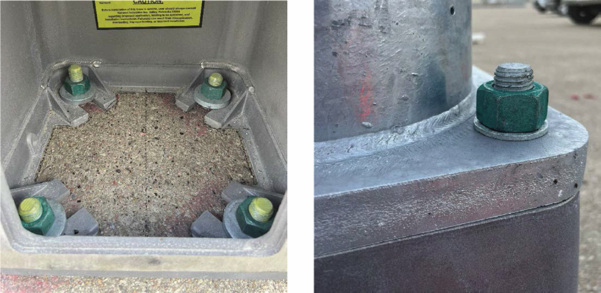
The breakaway transformer base was fabricated from ASTM 356-T6 aluminum and measured 15.38 in. square at the base, tapering to 13.13 in. square at the top. Four 1-in.-diameter, 4-in.-long ASTM A325 bolts connected the luminaire pole to the breakaway base with a top bolt circle diameter of 13.5 in. The breakaway base was fixed using four 1-in.-diameter by 12-in. ASTM A315 threaded rods with a bottom bolt circle diameter of 15 in. The threaded rods were doweled into the existing concrete apron with a high-modulus, high-strength epoxy bonding/grouting adhesive. The embedment depth of the threaded rods was 16 in. The top surface of the base assembly was mounted at a height of 17 in. above the existing concrete apron. An aluminum access door was located on the transformer base for the installation and examination of electrical wires. In this test, the transformer base door opening was located on the back side (non-impact side).
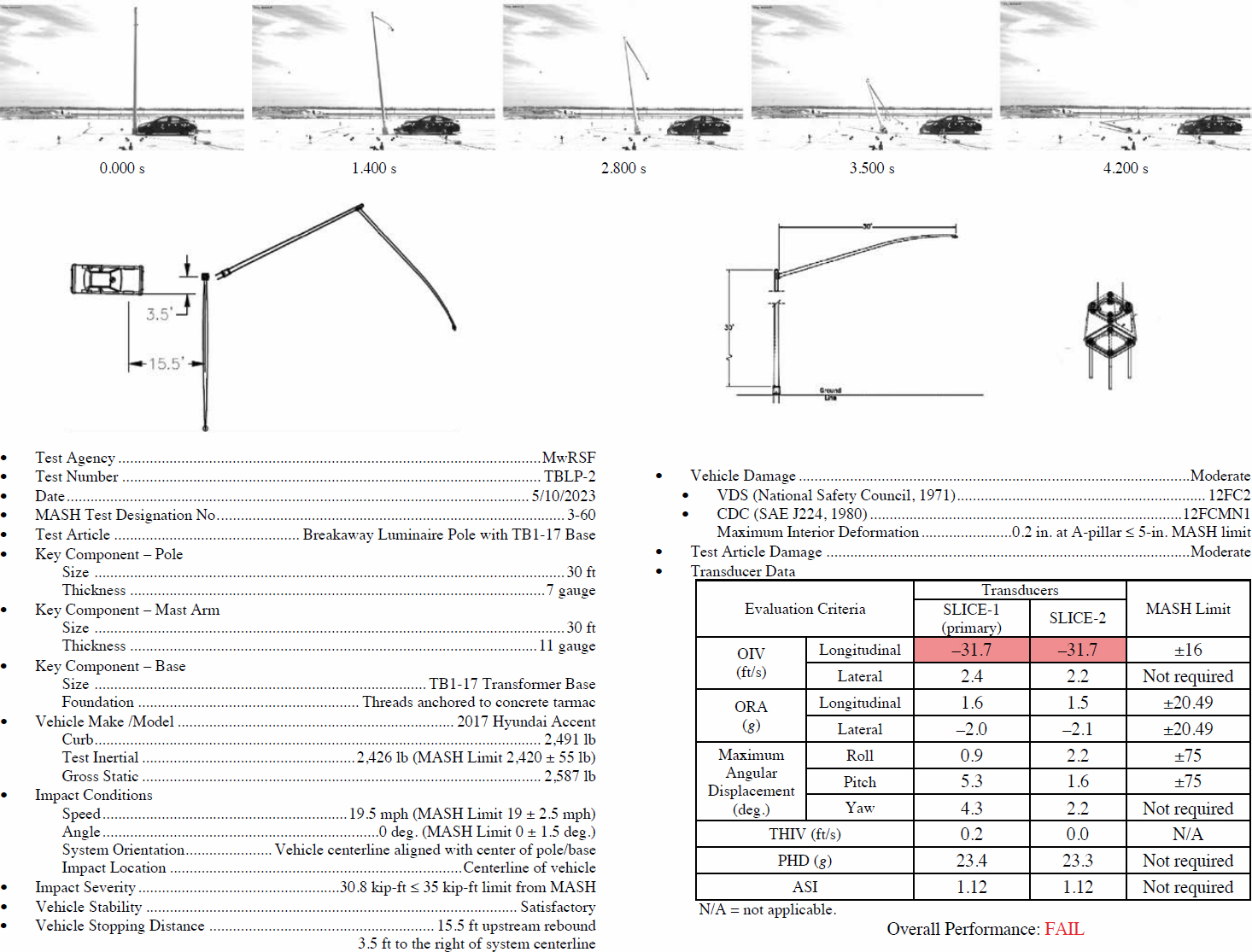
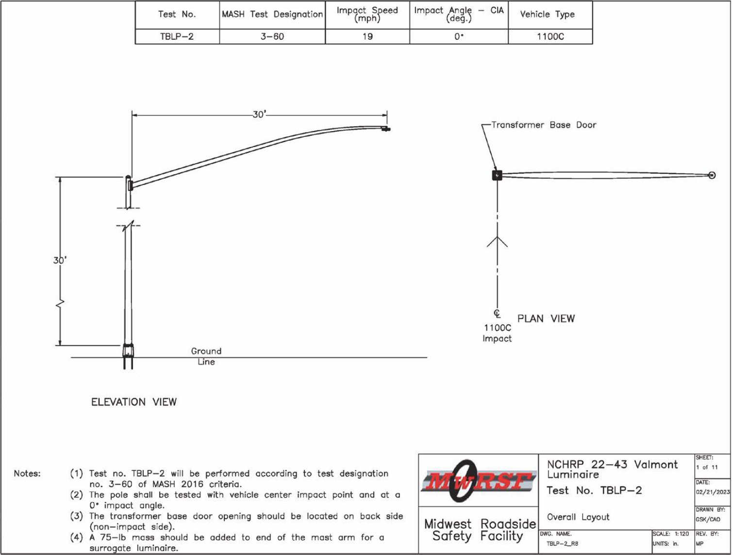
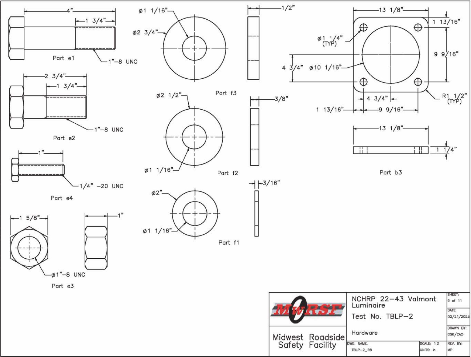
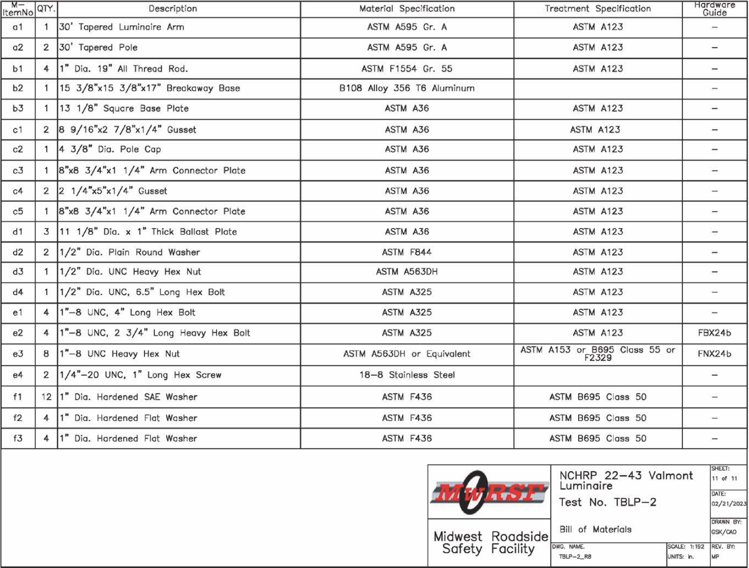
2.3.2 Test No. TBLP-2
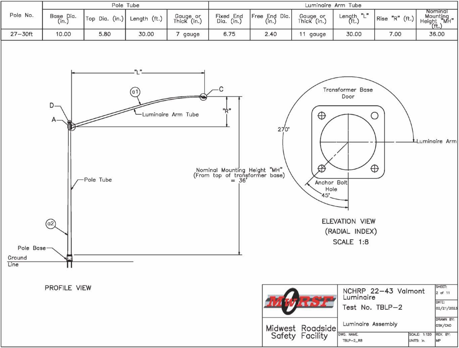
In this test, a 30-ft-tall pole with single 30-ft mast arms mounted on the TB1-17 transformer base was crash tested under MASH Test No. 3-60. Test No. TBLP-2 used the same type of breakaway transformer base that was used in Test No. TBLP-1. Similar to Test No. TBLP-1, the transformer base door opening was located on the back side (non-impact side). The breakaway luminaire pole and the transformer base details are shown in Figures 16 through 26, and photographs of the system are shown in Figures 27 through 29. Material specifications, mill certifications, and certificates of conformity for the system materials are in Appendix A.
The luminaire pole had a diameter of 10 in. at the base tapering off to 5.8 in. at the top with a 7-gauge wall thickness. The steel pole was manufactured to ASTM A595 Grade A and was hot-dip galvanized in accordance with ASTM A123. The luminaire pole had a maximum mounting height of 36 ft from the top of the mast arm to the top of the pole base. The height to the top of the luminaire pole (excluding rain cap) was 31 ft 6 in. from the ground.
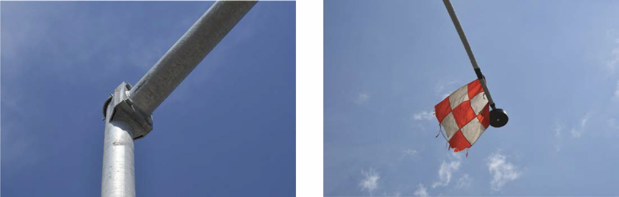
The single 11-gauge mast arm was attached to the luminaire 6 in. below the top of the luminaire pole. The mast arm extended outward from the face of the luminaire pole a total of 30 ft and upward above the top of the luminaire pole a total of 7 ft. The mast arm extended outward perpendicular to the direction of the impact. A 75-lb mass was added to the end of arm as a surrogate luminaire. The total weight of the structure (i.e., pole, mast arm, connections, surrogate luminaire, and base plate) was 824 lb.
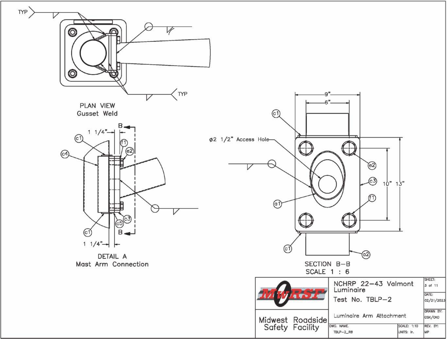
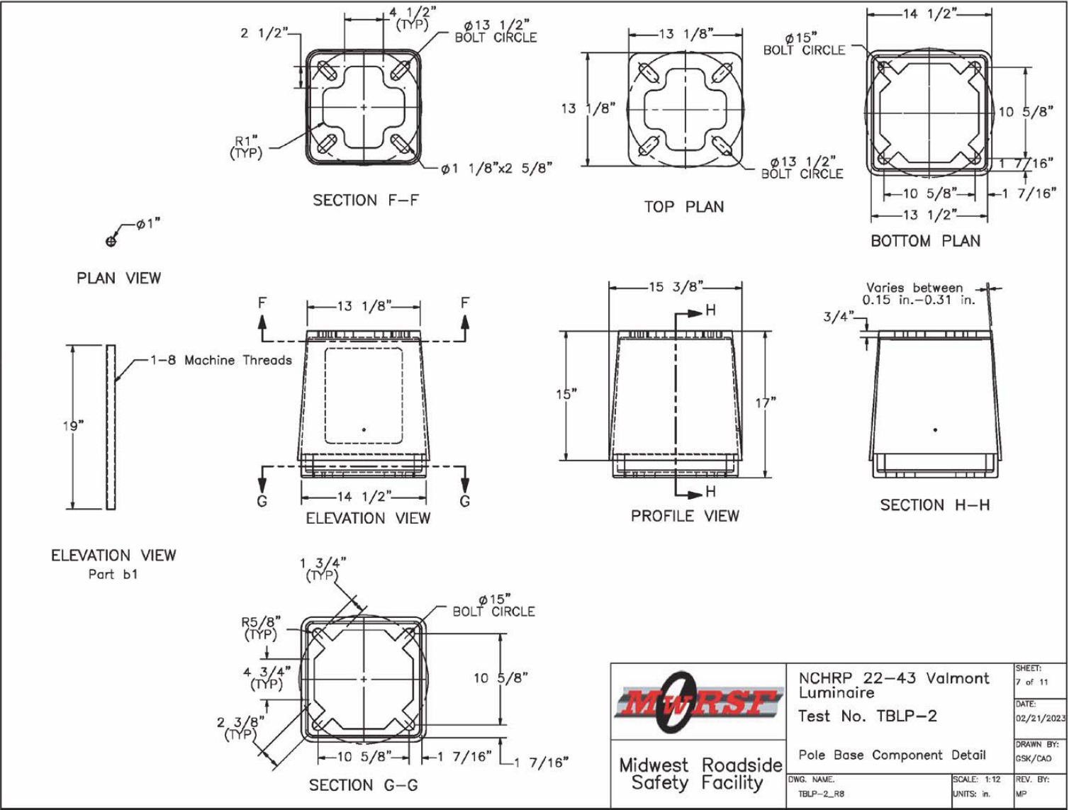
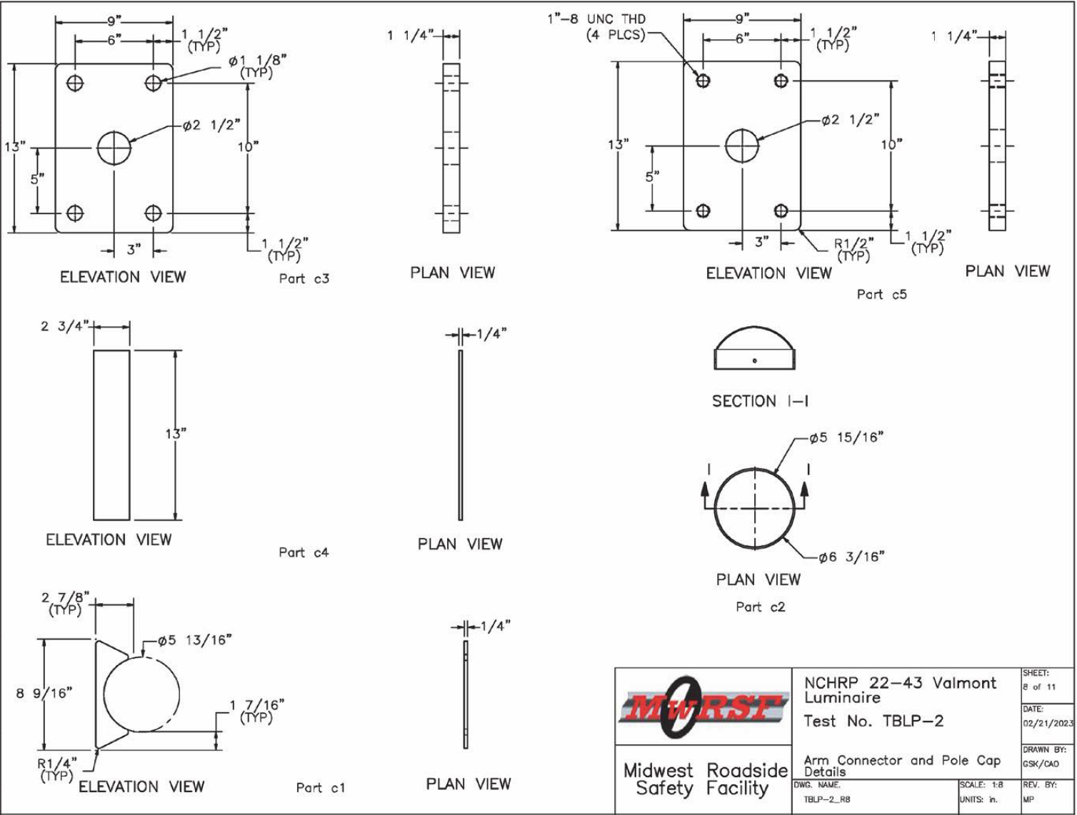
A four-bolt attachment with four 1-in.-diameter, A153 galvanized hex bolts was used to connect the mast arm to the luminaire pole. The attachment simplex consisted of a 1¼-in.-thick ASTM A36 steel plate on the pole side and a 1¼-in.-thick ASTM A36 steel plate on the mast arm side, as shown in Figure 18. The bottom of the pole was welded to a 1¼-in.-thick, 13.13-in.-square steel base plate. The mast arm was made of ASTM A595 Grade A steel.
2.4 Test Conditions
2.4.1 Test Facility
The luminaire pole tests were conducted at the MwRSF Outdoor Test Site, located at the Lincoln Air Park on the northwest side of the Lincoln Municipal Airport, approximately 5 miles northwest of the University of Nebraska–Lincoln.
2.4.2 Vehicle Tow and Guidance System
A reverse-cable tow system with a 1:2 mechanical advantage was used to propel the test vehicles. The distance traveled and the speed of the tow vehicle were one-half that of the test vehicles. The test vehicles were released from the tow cable before impact with the barrier system. A digital speedometer on the tow vehicle increased the accuracy of the test vehicles’ impact speed.


A vehicle guidance system developed by Hinch (Hinch et al. 1986) was used to steer the test vehicles. A guide flag, attached to the left-front wheel for Test Nos. TBLP-1 and TBLP-2, and the guide cable were sheared off before impact with the pole system. The ⅜-in.-diameter guide cable was tensioned to approximately 3,500 lb and supported both laterally and vertically every 100 ft by hinged stanchions. The hinged stanchions stood upright while holding up the guide cable. As the vehicle was towed down the line, the guide flag struck and knocked each stanchion to the ground.
2.4.3 Test Vehicles
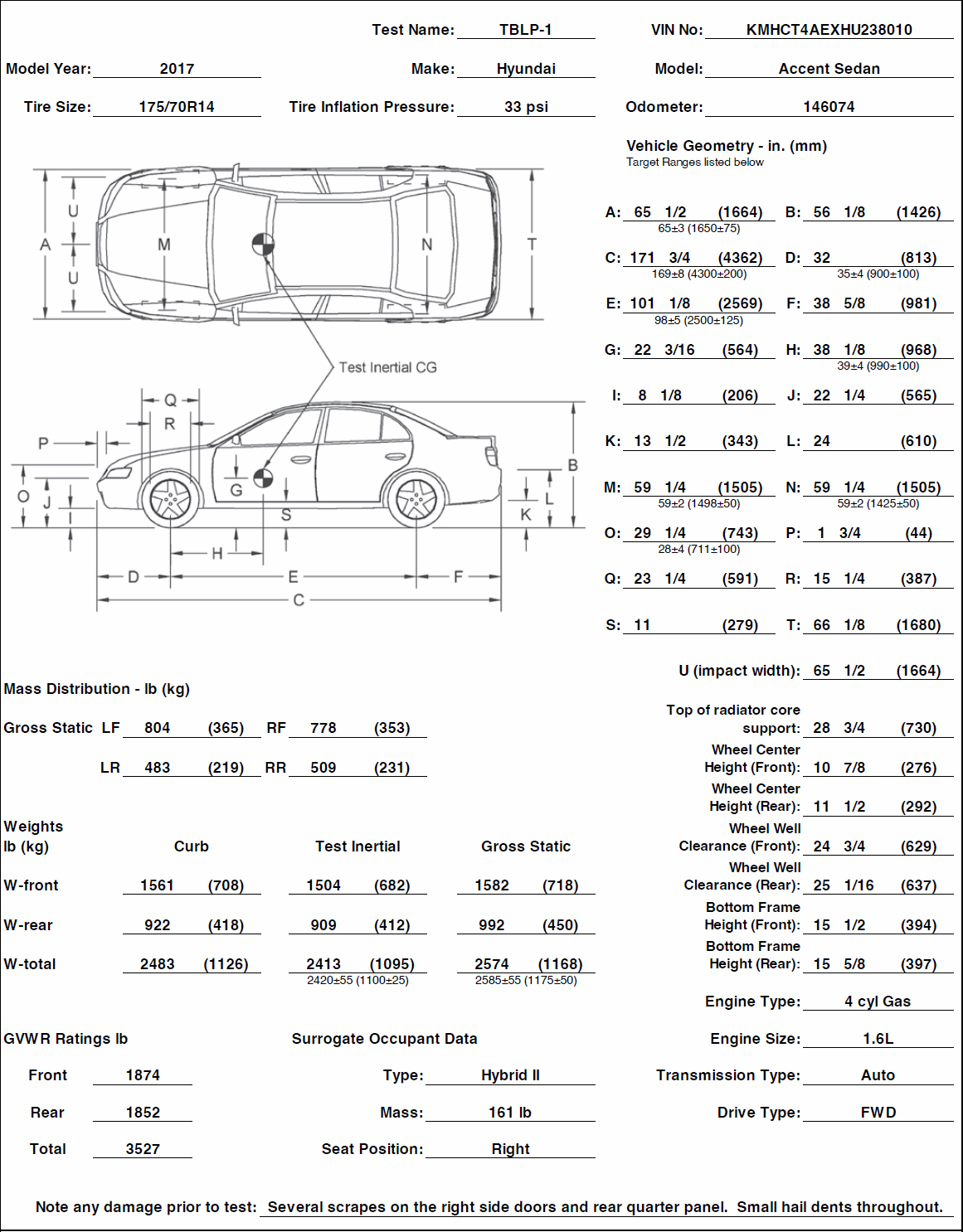
In Test No. TBLP-1, a 2017 Hyundai Accent was used as the test vehicle. The curb, test inertial, and gross static vehicle weights were 2,483 lb, 2,413 lb, and 2,574 lb, respectively. The test vehicle is shown in Figures 30 and 31, and vehicle dimensions are shown in Figure 32. Ballast information and data used to calculate the location of the center of gravity (CG) are shown in Appendix B.
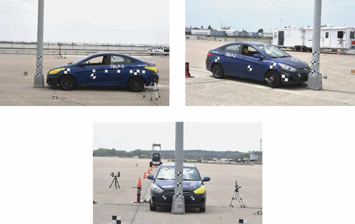
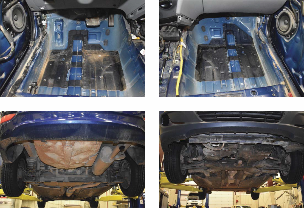
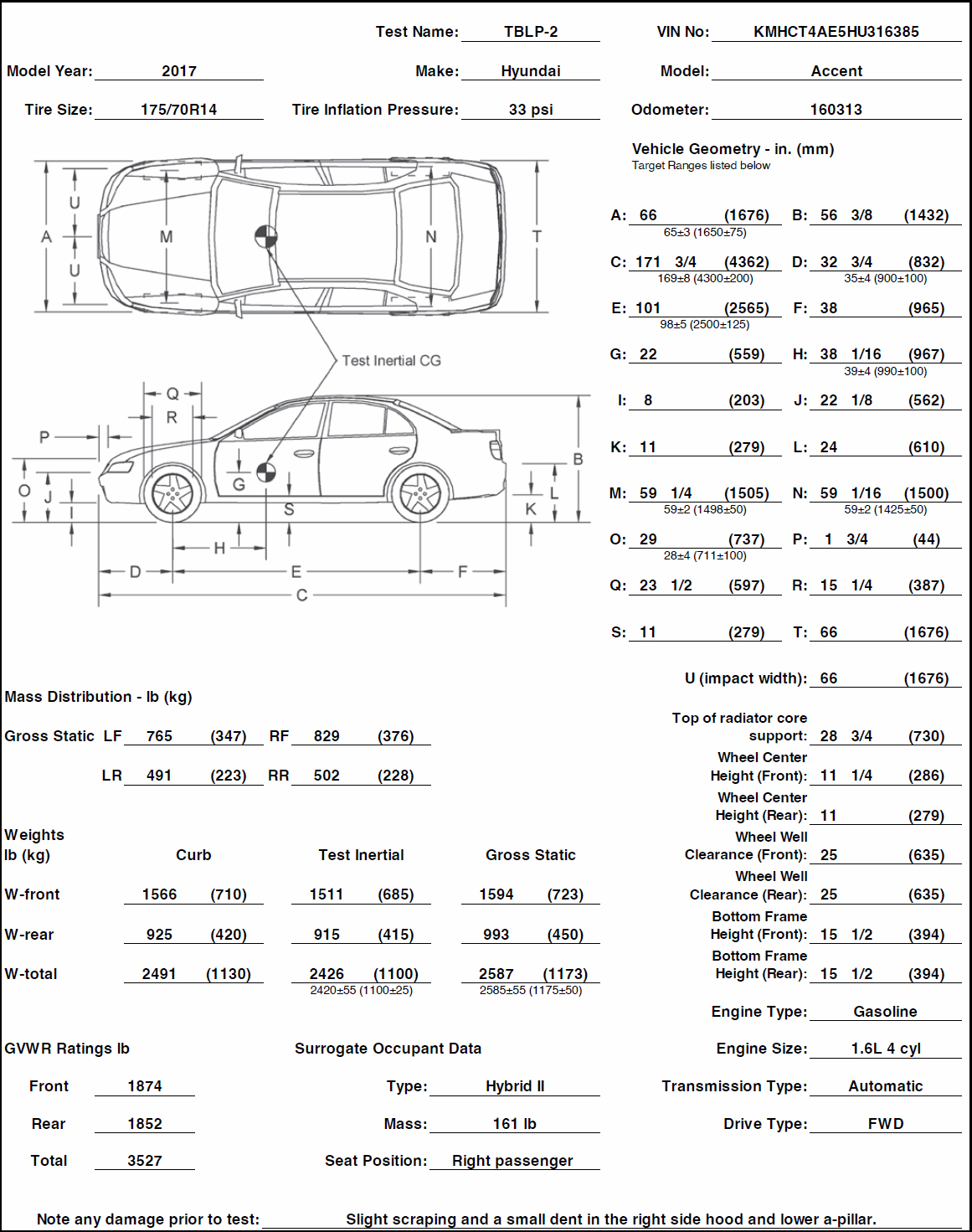
In Test No. TBLP-2, a 2017 Hyundai Accent was used as the test vehicle. The curb, test inertial, and gross static vehicle weights were 2,491 lb, 2,426 lb, and 2,587 lb, respectively. The test vehicle is shown in Figures 33 and 34, and vehicle dimensions are shown in Figure 35. Ballast information and data used to calculate the location of the CG are shown in Appendix B.


2.5 Full-Scale Crash Test No. TBLP-1
2.5.1 Weather Conditions
Test No. TBLP-1 was conducted on April 27, 2023, at approximately 11:00 a.m. The weather conditions per the National Oceanic and Atmospheric Administration (station 1439/KLNK) were reported and are shown in Table 13.
2.5.2 Test Description
Initial vehicle impact was to occur with the vehicle centerline aligned with the centerline of the system (as shown in Figure 36), which was recommended based on the simulation results conducted in Phase II. This orientation was selected to maximize resistance against base breakaway action, rather than the vehicle impacting the corner of the transformer base. This orientation would also maximize the potential for system interaction with the vehicle’s windshield and roof. Additionally, by setting up the system symmetrically, the likelihood of the pole landing at the center of the roof would increase and result in a higher propensity for roof crush as well as higher OIVs.
In Test No. TBLP-1, the 2,413-lb, 1100C small car impacted the 50-ft-tall pole with dual 15-ft-long mast arm at a speed of 19.3 mph and at an angle of 0 degrees. The vehicle came to rest approximately 8.5 ft downstream and 3.7 ft to the left of the system centerline. The brakes were not applied. A detailed description of the sequential impact events is shown in Table 14. Sequential photographs are shown in Figures 37 through 39.
Table 13. Weather conditions, Test No. TBLP-1.
| Temperature | 54°F |
| Humidity | 37% |
| Wind Speed | 15 mph |
| Wind Direction | South |
| Sky Conditions | Clear |
| Visibility | 10 statute miles |
| Pavement Surface | Dry |
| Previous 3-Day Precipitation | <0.01 in. |
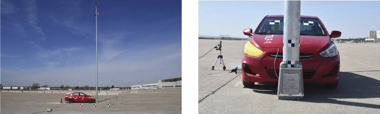
Table 14. Sequential description of impact events, Test No. TBLP-1.
| Time (s) | Event |
|---|---|
| 0.000 | Vehicle’s front bumper contacted pole. Front bumper was crushed and disengaged from vehicle. |
| 0.032 | Vehicle’s hood contacted pole and was crushed rearward. |
| 0.118 | Pole and transformer base disengaged from anchor. |
| 0.216 | Pole transformer base door disengaged. |
| 0.534 | Pole rotated counterclockwise. |
| 3.810 | Pole contacted vehicle’s roof and caused a small dent and slightly crushed windshield. |
| 3.856 | Pole contacted right A-pillar, and right A-pillar was dented. |
| 4.032 | Left surrogate luminaire at end of mast arm contacted ground. |
| 4.220 | Right surrogate luminaire at end of mast arm contacted ground, shattered, and detached. |
| 4.330 | Pole top cap disengaged. |
| 4.418 | Pole contacted vehicle’s right mirror and mirror detached. |
| 4.698 | Vehicle exited system. |
| 4.770 | Pole and transformer base contacted ground. |
2.5.3 System Damage
The TB1-17 transformer base fractured from the bottom upon impact and remained attached to the pole base plate. On the impact side, only a small piece remained attached to the ground, as shown in Figures 40 and 41. The pole fell on the right side of the vehicle. The door became detached from the transformer base. Pieces of the transformer base disengaged on the impact side. A crack originated from the impact side and extended to the back door opening hole. The pole and mast arms did not sustain any visible damage. The pole cap became detached. The mast arm and pole connection remained undamaged. The plates representing the surrogate luminaire at the end of the right-side mast arm and the flag became detached from the mast arm upon impact with the ground.
2.5.4 Vehicle Damage
The damage to the vehicle was moderate, as shown in Figures 42 through 44. The damage was concentrated on the front of the vehicle where the impact occurred. The bumper cover became disengaged, and the bumper was severely crushed into the radiator, resulting in damage to the radiator. The hood experienced crushing rearward at the lateral center of the panel. A small dent was present on the right-side leading edge of the roof. Additionally, two small dents were observed on the right side of the vehicle, one on the A-pillar and the other above the right-front window. The right mirror became detached, and the windshield sustained a slight crushing of 0.1 in. at its upper right corner. The front engine and transmission cross member were crushed rearward.
The maximum occupant compartment intrusions are listed in Table 15 along with the intrusion limits established in MASH for various areas of the occupant compartment. Complete occupant compartment and vehicle deformations and the corresponding locations are provided in Appendix C. MASH defines intrusion or deformation as the occupant compartment being deformed and reduced in size with no observed penetration. There was no penetration into the occupant compartment, and none of the established MASH deformation limits were violated. Outward deformations, which are denoted as negative numbers in Appendix C, are not considered crush toward the occupant and are not evaluated by the MASH safety criteria.


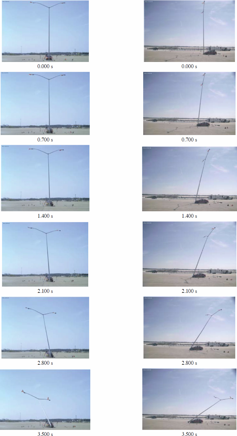

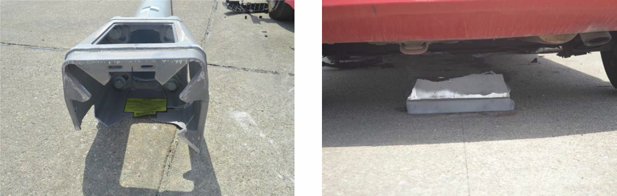
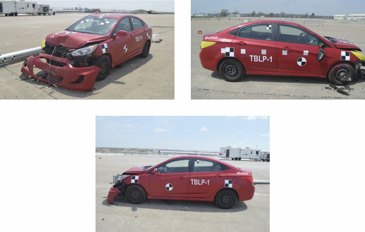
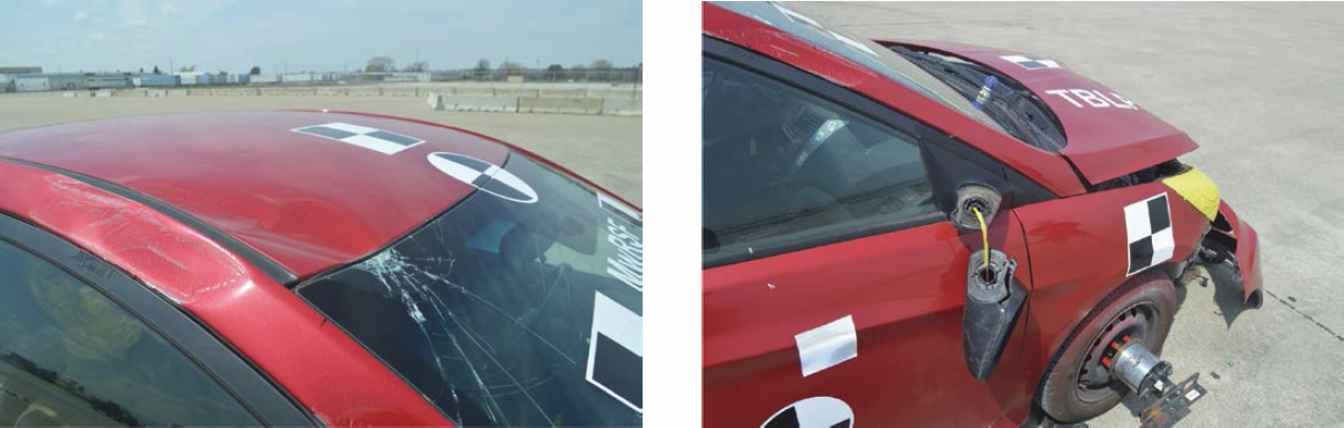
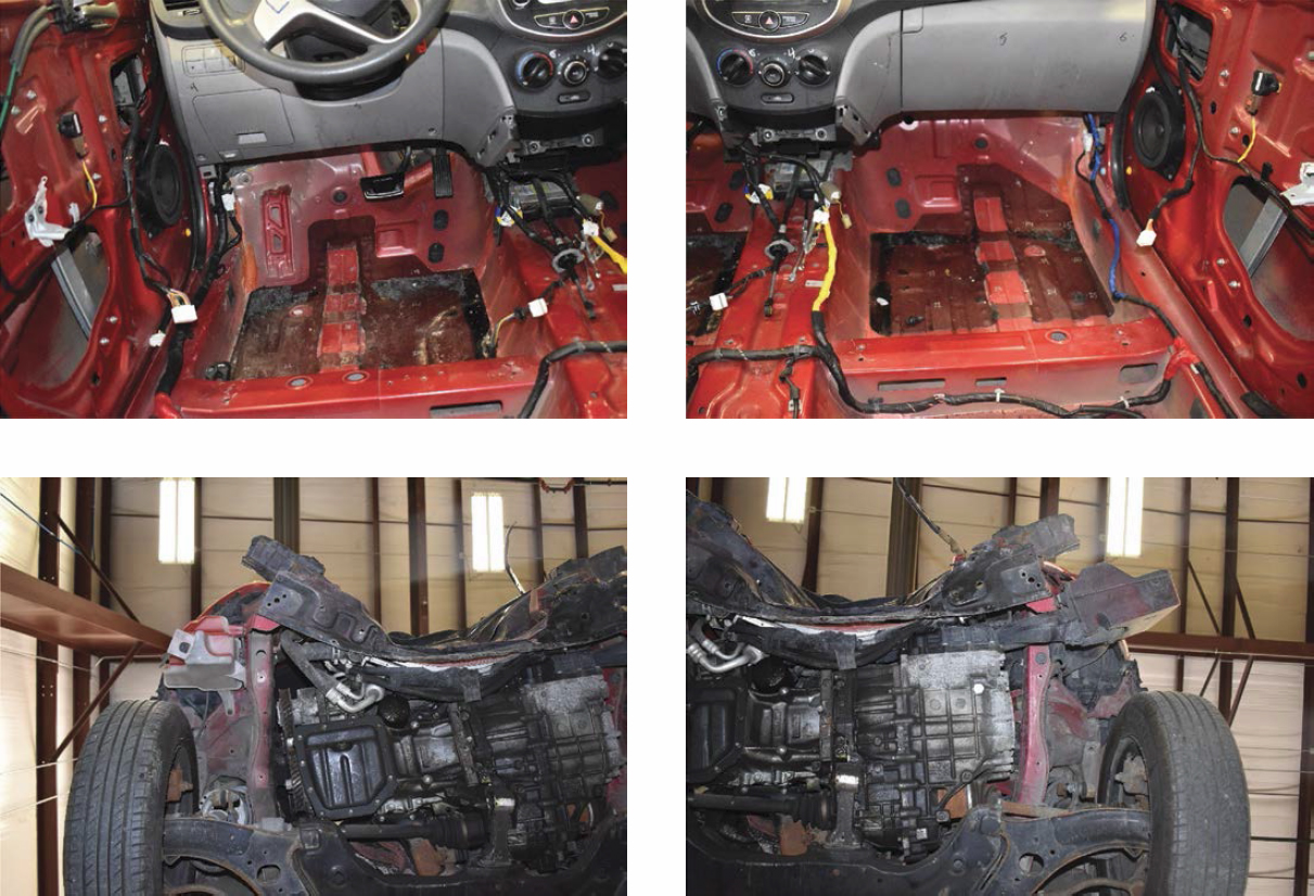
Table 15. Maximum occupant compartment intrusion by location, Test No. TBLP-1.
| Location | Maximum Intrusion [in. (mm)] | MASH Allowable Intrusion [in. (mm)] |
|---|---|---|
| Wheel Well and Toe Pan | 0.1 (3) | ≤9 (229) |
| Floor Pan and Transmission Tunnel | 0.1 (3) | ≤2 (305) |
| A-Pillar | 0.1 (3) | ≤5 (127) |
| A-Pillar (Lateral) | 0.0* (0) | ≤3 (76) |
| B-Pillar | 0.0 (0) | ≤5 (127) |
| B-Pillar (Lateral) | 0.0* (0) | ≤3 (76) |
| Side Front Panel (in Front of A-Pillar) | 0.0* (0) | ≤12 (305) |
| Side Door (Above Seat) | 0.0* (0) | ≤9 (229) |
| Side Door (Below Seat) | 0.0* (0) | ≤12 (305) |
| Roof | 0.0 (0) | ≤4 (102) |
| Windshield | 0.1 (3) | ≤3 (76) |
| Side Window | Intact | No shattering resulting from contact with structural member of test article |
| Dash | 0.0 (0) | N/A |
Notes: N/A = no MASH criteria exist for this location; * Negative value reported as 0.0. See Appendix C for further information.
Table 16. Summary of OIV, ORA, THIV, PHD, and ASI values, Test No. TBLP-1.
| Evaluation Criteria | Transducer | MASH Limit | ||
|---|---|---|---|---|
| SLICE-1 (Primary) | SLICE-2 | |||
| OIV (ft/s) | Longitudinal | –17.8 | –17.9 | ±16 |
| Lateral | –0.2 | –0.2 | Not required | |
| ORA (g) | Longitudinal | 1.2 | 1.3 | ±20.49 |
| Lateral | 2.9 | 3.6 | ±20.49 | |
| Maximum Angular Displacement (deg.) | Roll | 2.8 | 2.0 | ±75 |
| Pitch | 2.3 | 2.6 | ±75 | |
| Yaw | –5.3 | –5.2 | Not required | |
| THIV (ft/s) | 17.7 | 18.0 | N/A | |
| PHD (g) | 1.8 | 2.0 | Not required | |
| ASI | 0.74 | 0.72 | Not required | |
Note: N/A = not applicable. Salmon-colored cells = OIV exceeded limit.
2.5.5 Occupant Risk
The calculated OIVs and maximum 0.010-s average ORAs in both the longitudinal and lateral directions, as determined from the accelerometer data, are shown in Table 16. ORAs were within suggested limits, as provided in MASH. However, the longitudinal OIV of 17.8 ft/s exceeded the MASH limit of 16 ft/s. The calculated ASI, THIV, and PHD values are also shown in Table 16. The recorded data from the accelerometers and the rate transducers are shown graphically in Appendix D.
2.5.6 Discussion
In Test No. TBLP-1, the TB1-17 transformer base activated as expected and in a predictable manner. However, the pole did not land on the center of the vehicle, which was the critical scenario that was anticipated. A summary of the test results and sequential photographs is shown in Figure 45. Detached elements, fragments, or other debris from the test article did not penetrate or show potential to penetrate the occupant compartment and did not present an undue hazard to other traffic, pedestrians, or work-zone personnel. Deformations of, or intrusions into, the occupant compartment that could have caused serious injury did not occur. Vehicle roll, pitch, and yaw angular displacements were deemed acceptable because they did not adversely influence occupant risk nor cause rollover. After impact, the vehicle traversed the foundation and continued forward until it came to a stop downstream of the system. The ORAs were within suggested limits; however, the longitudinal OIV of 17.8 ft/s exceeded the MASH limit of 16 ft/s. Therefore, Test No. TBLP-1 was determined to be unacceptable according to the MASH safety performance criteria for Test No. 3-60.
2.6 Full-Scale Crash Test No. TBLP-2
2.6.1 Weather Conditions
Test No. TBLP-2 was conducted on May 10, 2023, at approximately 1:30 p.m. The weather conditions per the National Oceanic and Atmospheric Administration (station 1439/KLNK) were reported and are shown in Table 17.
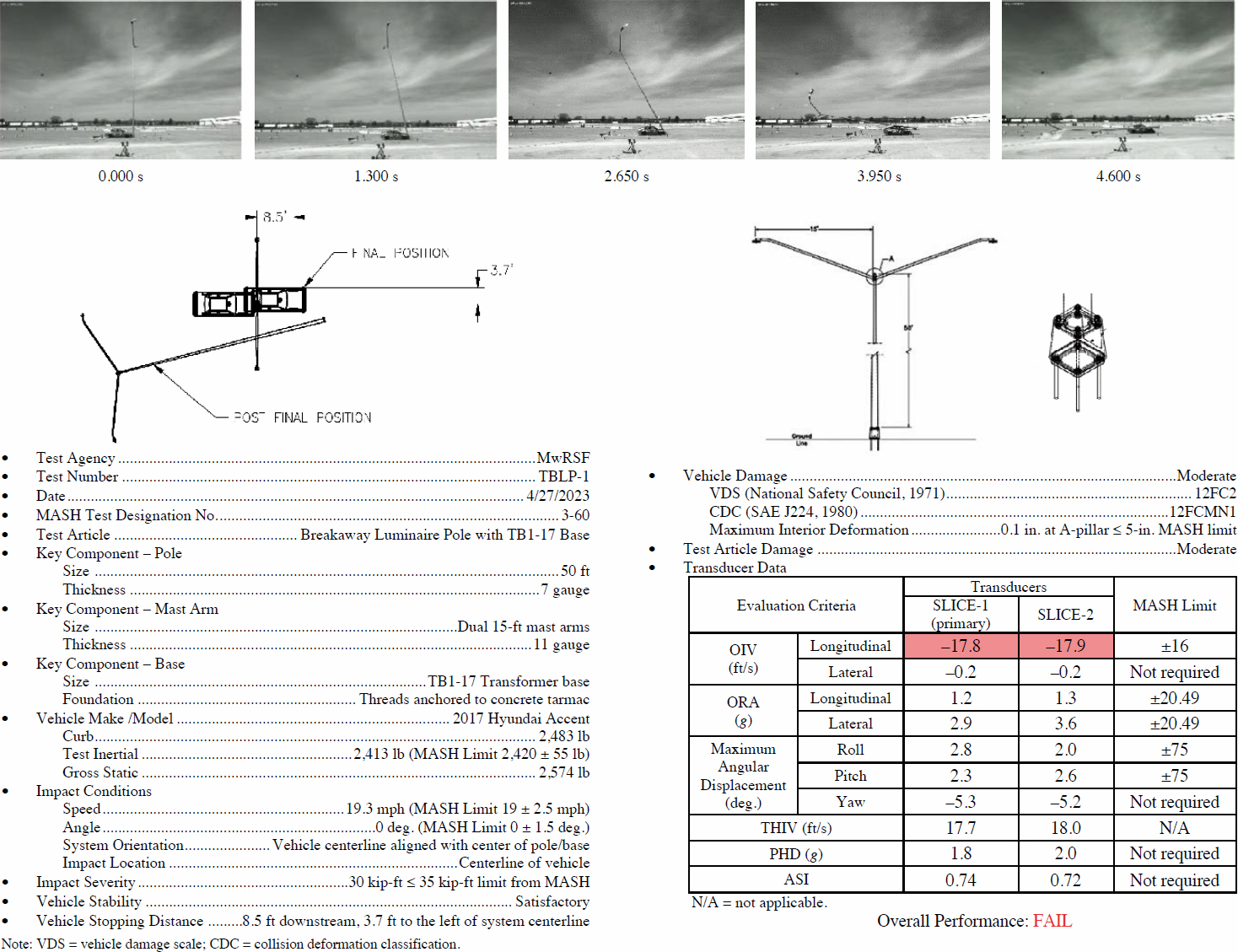
Table 17. Weather conditions, Test No. TBLP-2.
| Temperature | 87°F |
| Humidity | 35% |
| Wind Speed | 6 mph |
| Wind Direction | South |
| Sky Conditions | Partly cloudy |
| Visibility | 10 statute miles |
| Pavement Surface | Dry |
| Previous 3-Day Precipitation | <0.01 in. |
2.6.2 Test Description
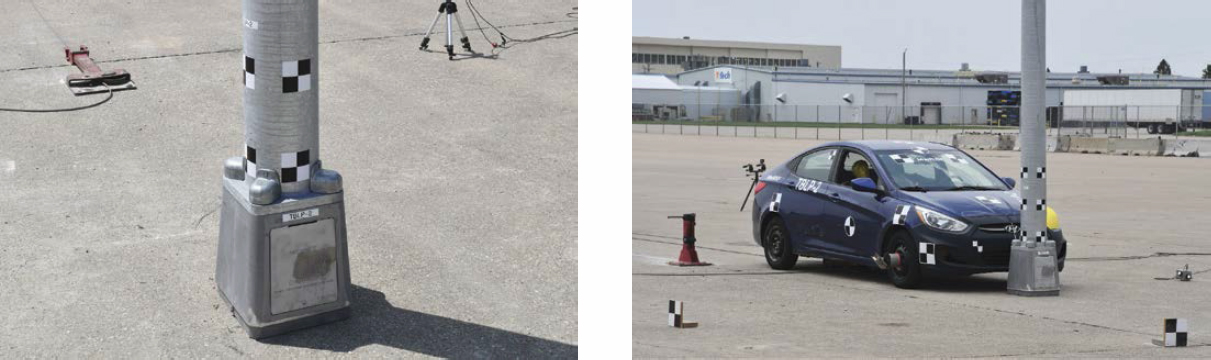
Initial vehicle impact was to occur with the vehicle centerline aligned with the centerline of the system, as shown in Figure 46, which was recommended based on the simulation results conducted in Phase II. This orientation was selected to maximize resistance against base breakaway action, rather than the vehicle impacting the corner of the transformer base. This orientation would also maximize the potential for system interaction with the vehicle’s windshield and roof. Additionally, by setting up the system symmetrically, the likelihood of the pole landing at the center of the roof would increase and result in a higher propensity for roof crush as well as higher OIVs.
In Test No. TBLP-2, the 2,426-lb, 1100C small car impacted the 30-ft-tall pole with a single 30-ft-long mast arm at a speed of 19.5 mph and at an angle of 0 degrees. The vehicle rebounded after the impact and came to rest 15.5 ft longitudinally upstream. The transformer base did not activate. The brakes were not applied. A detailed description of the sequential impact events is contained in Table 18. Sequential photographs are shown in Figures 47 through 49.
2.6.3 System Damage
In this test, the desired breakaway activation of the TB1-17 transformer base did not occur upon impact. During the impact event, following the vehicle rebound, a crack initiated on the left-side wall of the base and gradually extended to the back and right-side walls of the base.
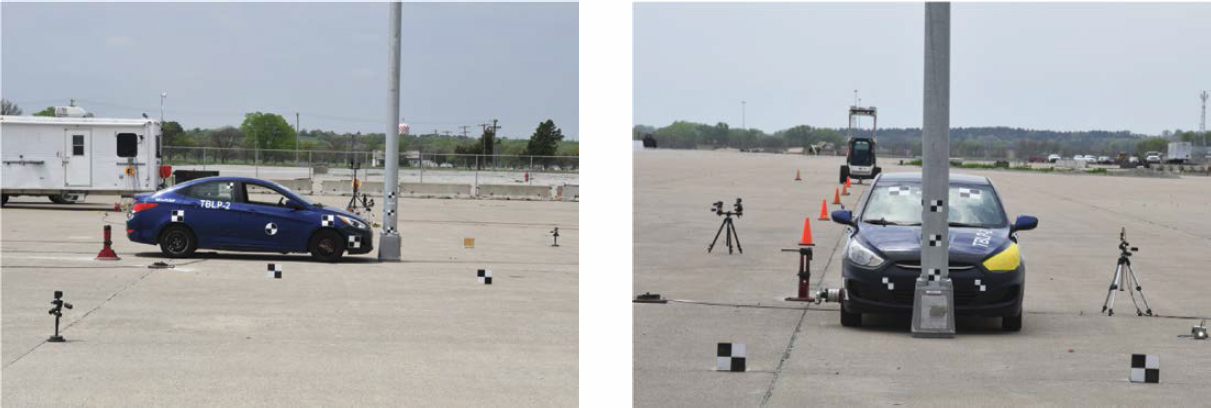
Table 18. Sequential description of impact events, Test No. TBLP-2.
| Time (s) | Event |
|---|---|
| 0.000 | Vehicle’s front bumper contacted pole. Front bumper was crushed in center and disengaged from vehicle. |
| 0.032 | Vehicle’s hood contacted pole and was crushed rearward. |
| 0.076 | Transformer base fractured from anchor. |
| 0.156 | Pole rotated clockwise. |
| 0.632 | Vehicle exited system. |
| 1.810 | Pole and transformer base disengaged from anchor. |
| 3.404 | Surrogate luminaire at end of mast arm contacted ground, shattered, and detached. |
| 3.468 | Pole top cap disengaged. |
| 3.884 | Pole and transformer base became airborne. |
| 4.024 | Pole and transformer base contacted ground. |
| 4.026 | Top of pole contacted ground. |
The weight of the arm ultimately led to the fracture of the base. The pole fell toward the right side, nearly perpendicular to the direction of impact, without making contact with the vehicle, as shown in Figures 50 and 51. The impact-side wall remained intact and connected to the ground. The access door became detached from the transformer base, while pieces of the base disengaged on the left and back sides. No visible damage was sustained by the pole and mast arm. The pole cap became detached, but the connection between the mast arm and pole remained undamaged.
2.6.4 Vehicle Damage
The damage to the vehicle was moderate, as shown in Figures 52 through 54. The damage was concentrated on the front of the vehicle where the impact had occurred. The bumper was crushed and dented in the center and pushed significantly rearward into the radiator. The hood was crushed and dented at the leading edge at the lateral center. The damaged area was pushed rearward, and the hood was bowed upward. The vehicle’s transmission pan cracked, and the right rear corner of the oil pan was fractured and bent downward. The front engine and transmission cross member were crushed rearward.
The maximum occupant compartment intrusions are listed in Table 19 along with the intrusion limits established in MASH for various areas of the occupant compartment. Complete occupant compartment and vehicle deformations and the corresponding locations are provided in Appendix C. MASH defines intrusion or deformation as the occupant compartment being deformed and reduced in size with no observed penetration. There was no penetration into the occupant compartment, and none of the established MASH deformation limits were violated.
2.6.5 Occupant Risk
The calculated OIVs and maximum 0.010-s average ORAs in both the longitudinal and lateral directions, as determined from the accelerometer data, are shown in Table 20. The ORAs were within suggested limits, as provided in MASH. However, the longitudinal OIV of 31.7 ft/s exceeded the MASH limit of 16 ft/s. This was primarily caused by the base not being activated during the impact event. The calculated ASI, THIV, and PHD values are also shown in Table 20. The recorded data from the accelerometers and the rate transducers are shown graphically in Appendix E.
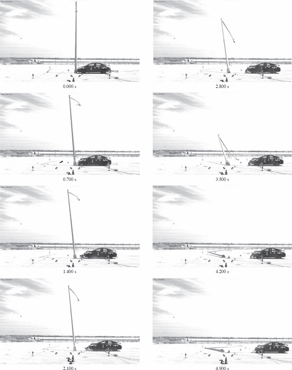
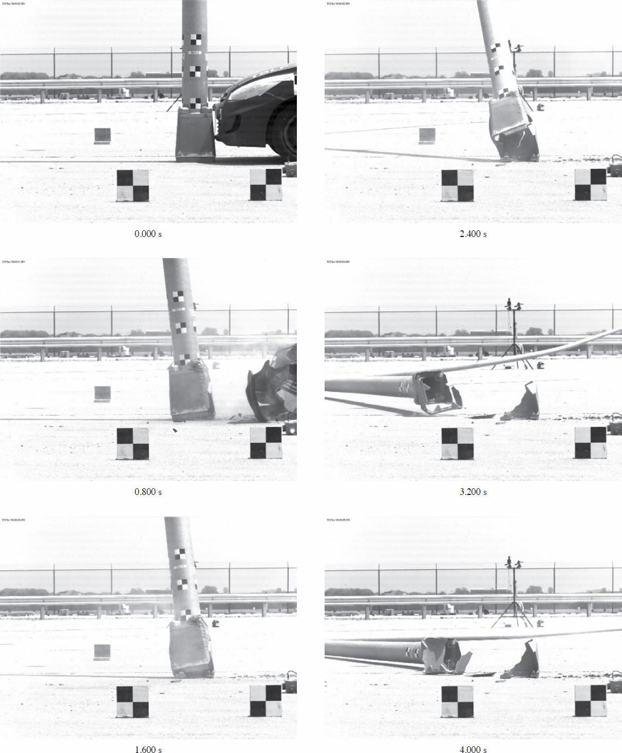
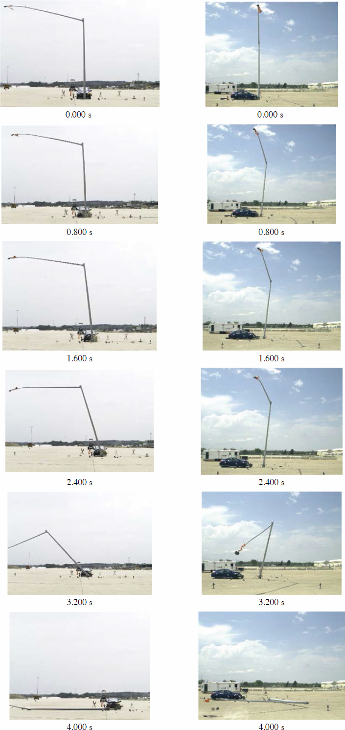

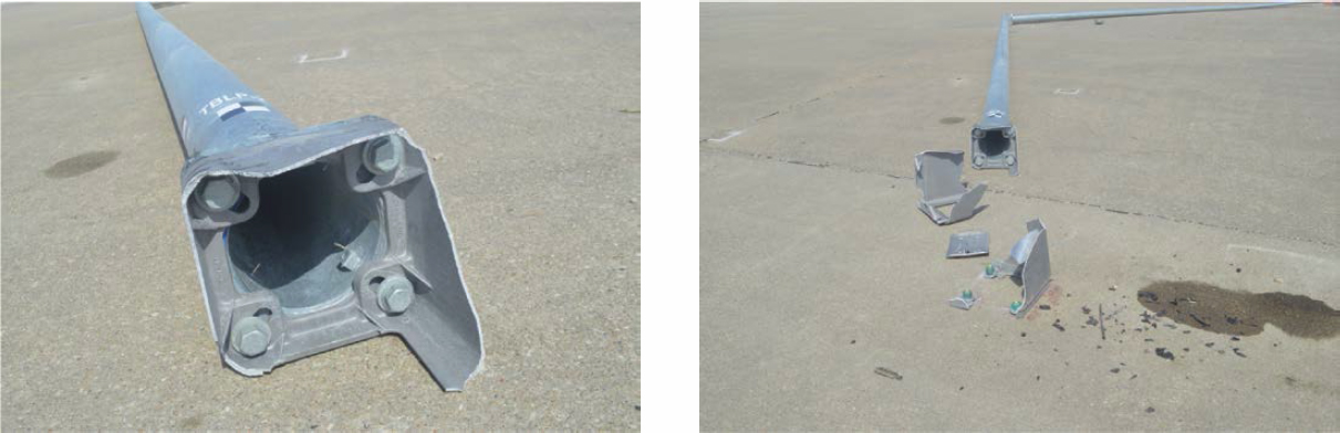
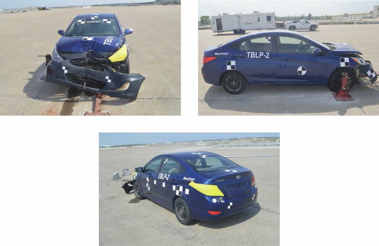
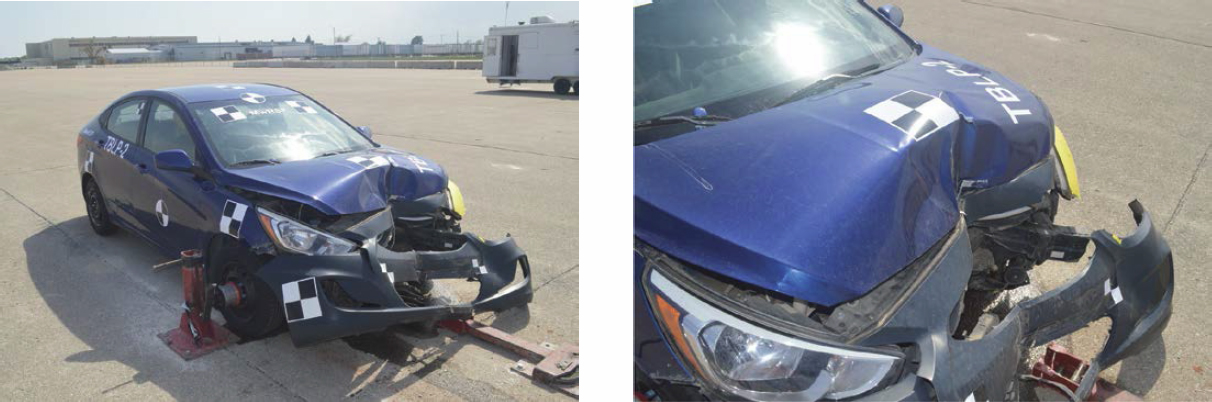

Table 19. Maximum occupant compartment intrusion by location, Test No. TBLP-2.
| Location | Maximum Intrusion [in. (mm)] | MASH Allowable Intrusion [in. (mm)] |
|---|---|---|
| Wheel Well and Toe Pan | 0.1 (3) | ≤9 (229) |
| Floor Pan and Transmission Tunnel | 0.1 (3) | ≤12 (305) |
| A-Pillar | 0.2 (5) | ≤5 (127) |
| A-Pillar (Lateral) | 0.2 (5) | ≤3 (76) |
| B-Pillar | 0.1 (3) | ≤5 (127) |
| B-Pillar (Lateral) | 0.2 (5) | ≤3 (76) |
| Side Front Panel (in Front of A-Pillar) | 0.1 (3) | ≤12 (305) |
| Side Door (Above Seat) | 0.1 (3) | ≤9 (229) |
| Side Door (Below Seat) | 0.1 (3) | ≤12 (305) |
| Roof | 0.0 (0) | ≤4 (102) |
| Windshield | 0.0 (0) | ≤3 (76) |
| Side Window | Intact | No shattering resulting from contact with structural member of test article |
| Dash | 0.0 (0) | N/A |
Note: N/A = no MASH criteria exist for this location.
Table 20. Summary of OIV, ORA, THIV, PHD, and ASI values, Test No. TBLP-2.
| Evaluation Criteria | Transducer | MASH Limit | ||
|---|---|---|---|---|
| SLICE-1 (primary) | SLICE-2 | |||
| OIV (ft/s) | Longitudinal | –31.7 | –31.7 | ±16 |
| Lateral | 2.4 | 2.2 | Not required | |
| ORA (g) | Longitudinal | 1.6 | 1.5 | ±20.49 |
| Lateral | –2.0 | –2.1 | ±20.49 | |
| Maximum Angular Displacement (deg.) | Roll | 0.9 | 2.2 | ±75 |
| Pitch | 5.3 | 1.6 | ±75 | |
| Yaw | 4.3 | 2.2 | Not required | |
| THIV (ft/s) | 0.2 | 0.0 | N/A | |
| PHD (g) | 23.4 | 23.3 | Not required | |
| ASI | 1.12 | 1.12 | Not required | |
Note: N/A = not applicable. Salmon-colored cells = OIV exceeded limit.
2.6.6 Discussion
In Test No. TBLP-2, the desired breakaway activation of the TB1-17 transformer base did not occur upon impact. Upon impact, the vehicle rebounded, a crack initiated on the left-side wall of the base and gradually extended to the back and right-side walls of the base, and the pole fell to the right side (with respect to the impact direction) without contacting the vehicle. Possible factors contributing to the base not activating could be a lower center of gravity (closer to the ground), variations in base material properties, and differences in the initial stress state of the base due to the mast arm configuration. A summary of the test results and sequential photographs are shown in Figure 55.
Detached elements, fragments, or other debris from the test article did not penetrate or show potential to penetrate the occupant compartment and did not present an undue hazard to other traffic, pedestrians, or work-zone personnel. Deformations of, or intrusions into, the occupant compartment that could have caused serious injury did not occur. The ORAs were within suggested limits. However, the longitudinal OIV of 31.7 ft/s exceeded the MASH limit of 16 ft/s. This behavior was primarily caused by the base not being activated during the impact event. Therefore, Test No. TBLP-2 was determined to be unacceptable according to the MASH safety performance criteria for Test No. 3-60.