Uncrewed Aerial Systems Applications for Bridge Inspections: Element-Level Bridge Data Collection (2024)
Chapter: 2 Research Approach
CHAPTER 2
Research Approach
To meet the research objectives, a literature review was conducted to establish the current state of the art of UAS related to the inspection of civil infrastructure, including bridges. The literature review identified relevant knowledge gaps, which were used to identify 22 structures to be inspected in the following phase of the project. In that phase, the structures were inspected with two UAS form factors and the recorded video, and imagery was reviewed to assess the accessibility of elements, the detectability of deficiencies, and sensor adaptability to environmental conditions, among others. These results were valuable when guidelines were developed for selecting UAS for bridge inspections and flight procedures were created for common bridge types and elements.
2.1 Literature Review
A literature review was conducted to establish the current state of the art of UAS inspections, including uses for inspecting civil infrastructure, the available technology, and the regulations for commercial UAS in the United States. The review also included examples of operator training requirements from various bridge owners, as well as examples of UAS used for bridge inspections in the United States and abroad. Finally, the review briefly covered data processing of UAS inspection video and imagery and common deliverables derived from that data. Sources for this literature review include reports from research sponsored by state and federal transportation agencies, state DOT UAS operations manuals, published journal articles and conference proceedings, and the electronic Code of Federal Regulations (eCFR).
2.1.1 UAS Inspection of Civil Infrastructure
The use of uncrewed aircraft has expanded in recent years as state and federal agencies explore UAS and implement the technology into their operations. Following the nomenclature of the FAA, this report uses “uncrewed aircraft” to refer to the aircraft itself, whereas “UAS” refers to the aircraft, communications link, control station, and associated equipment. Uncrewed aircraft are also commonly referred to as drones.
Within the realm of civil infrastructure, UAS have been used in several applications because they can enable higher quality and faster data collection at lower costs compared with previous methods. State DOTs and federal agencies have used UAS for construction and traffic monitoring, land surveying and mapping (O’Neil-Dunne 2016), and aerial photography (Snyder and Zajkowski 2016). UAS have also been widely used for structural inspections of high-mast light poles and communication towers (Otero et al. 2015; Sa, Hrabar, and Corke 2015; Gillins et al. 2018; Titze, Stewart, and Stock 2018); penstocks, pump stations, and tunnels [Brooks et al. 2015; Özaslan et al. 2015; United Nations Economic and Social Commission for Asia and the Pacific (UNESCAP) 2019]; retaining walls and dams (Hallermann and Morgenthal 2014); ports (Marcotte et al. 2019); and rail lines (Sherrock and Neubecker 2018; Wishart et al. 2020).
Another aspect of civil infrastructure that has received extensive attention is using UAS to supplement Routine Inspections of structures in the National Bridge Inventory. In most cases, the UAS collected high-quality imagery comparable with that produced by traditional inspection methods, but without using specialized access equipment such as under bridge inspection trucks (UBITs) or aerial lifts. Although numerous studies have established that UAS can supplement routine bridge inspections, state agencies have been hesitant to implement UAS into their bridge inspection programs. Their main concerns are evolving federal regulations, practicality, cost, comparison with traditional methods, data storage, and whether UAS imagery will be allowed in an inspection report.
2.1.2 Current UAS Technologies
A wide range of UAS technology is available today, with varying sizes, payloads, fuel types, and configurations. In the current market, the most common configurations for civil infrastructure applications are rotary and fixed-wing uncrewed aircraft powered by electric motors and rechargeable batteries. Sensors used for civil infrastructure applications are commonly RGB, thermal, and infrared cameras.
With respect to bridge inspections, the most popular uncrewed aircraft are rotary aircraft with four, six, or eight independently driven rotors. These can be specifically referred to as quad-, hexa-, or octocopters, respectively, but are more generally called multi-rotor aircraft. Electric ducted fan aircraft and nitro-powered single-rotor aircraft have also been used but have been supplanted by more maneuverable multi-rotor aircraft (Moller 2008). Multi-rotor aircraft are capable of vertical takeoffs and landings and can hover in place, making them well suited for bridge inspections. Flight times range from 10 to 30 minutes, but low battery temperatures have been shown to dramatically decrease flight times.
Available research indicates that the most commonly used off-the-shelf models for bridge inspections have been
- DJI Phantom, Mavic, Matrice, and Inspire;
- SenseFly Albris;
- Intel Falcon 8;
- Bergen hexacopter;
- Flyability Elios and Elios 2;
- Leica Aibot X6; and
- Trimble UX5.
Other researchers have built custom multi-rotor aircraft based on commercially available models like the DJI S800 or S900, or completely custom aircraft assembled from compatible parts. In most studies that used custom aircraft, the model was built and operated by an entity other than a DOT, such as a university research group or a consulting firm.
In August 2020, the Defense Innovation Unit of the Department of Defense (DOD) first published the Blue UAS list (https://www.diu.mil/blue-uas-cleared-list) with five airframes approved for use by federal agencies. As of July 2023, this list has expanded to include 15 fixed-wing and multi-rotor airframes. Development of the Blue UAS list was spurred by data security concerns regarding foreign-made drones being operated around national security assets. Although most bridges will not fall into this category, a bridge owner needs to be aware of which structures in its inventory would be national security assets. State or federal laws or procurement policies may also limit which UAS agencies may use.
In addition to the Blue UAS list, the Association for Uncrewed Vehicle Systems International is creating a Green (cleared) UAS list (https://www.auvsi.org/cleared-list). UAS on the Green list
will meet the security requirements of the Blue UAS list but are intended for commercial (non-defense) applications. However, inclusion on the Green list will expedite an aircraft’s addition to the Blue List, if requested.
Regarding UAS for bridge inspections, characteristics that have been useful are the ability to fly without a GPS signal, object detection and avoidance, and the ability to capture imagery of structures directly overhead. When inspecting the underside of a bridge deck, the aircraft is likely to lose GPS connection because of the overhead obstruction and the low penetrating power of GPS signals. Losing a GPS signal may eliminate or reduce the airframe’s ability to hold a certain position and altitude, requiring the remote pilot to manually control the aircraft or rely on other sensors (ultrasonic proximity sensors or first-person view cameras) for stability. Studies using stereovision cameras for navigation in GPS-denied environments have shown that the aircraft may drift when over water. Some researchers have avoided losing a GPS signal by flying the aircraft outside the structure while using a camera with an optical zoom to view the underside of the bridge deck. This inevitably leaves some areas inaccessible, especially as the width of the bridge deck increases.
Object detection and avoidance are useful not only for navigating without GPS signal, but also for maintaining a constant standoff distance from the structure. Maintaining a constant standoff distance while collecting still images is useful when post-processing imagery to create orthomosaics, 3-D models, or point clouds. An appropriate standoff distance also protects the structure and aircraft from inadvertent collisions caused by environmental conditions or remote pilot error. In controlled environments and in practice the standoff can be as little as 1 ft, but there is a necessary compromise between a safe standoff distance and the level of detail captured by a camera.
Important considerations when choosing a sensor for bridge inspections are sensor size (resolution), zoom capabilities, exposure control, weight, and cost. RGB cameras are the most common sensor for UAS bridge inspections and are used for the same purpose as in traditional inspections: to document the condition of the structure. Cameras can be integrated into the airframe or standalone models mounted to a gimbal controlled by either the remote pilot or a sensor operator. Standalone cameras can be handheld action cameras, like many GoPro models; digital single-lens reflex cameras, like a Nikon D800; or mirrorless digital cameras, like the Sony Alpha α7. GoPro cameras are popular because they are compact and inexpensive, but the camera is limited by a fixed aperture and lack of an optical zoom. Integrated cameras are lighter and smaller than stand-alone cameras but come at a cost of image resolution. However, the small size of integrated cameras also means the aircraft can be smaller, making the airframe more maneuverable in confined spaces. In this case, the increased accessibility may make up for the smaller sensor sizes of integrated cameras. The optical zoom capabilities of integrated cameras vary among systems but are usually less than those of stand-alone cameras. Digital single-lens reflex and mirrorless digital cameras offer the highest resolution available, but at a cost of size and weight. Most integrated and stand-alone cameras offer manual in-flight controls to adjust the exposure and account for low-light conditions.
There are no minimum requirements for camera resolution, just as there are no vision requirements for bridge inspectors, but 12 megapixels has been recommended as the minimum resolution for bridge inspection (Neubauer, Bullard, and Blunt 2021). Camera resolution is only one component, though, as image quality is also dependent on external factors, such as wind, vibration, illumination, and contrast, and internal factors, such as ISO (that is, the control of brightness), aperture, and shutter speed. One approach that has been proposed is to train sensor operators or bridge inspectors to recognize and correct poor image quality and to use automatic camera settings as much as possible.
2.1.3 FAA Regulations
The FAA is the regulatory authority responsible for the safe and efficient management of the national airspace and the use of the airspace by manned and uncrewed aircraft. Current policies
for the operation of small UAS (sUAS, under 55 lbs) in the national airspace are given in 14 CFR Part 107. An exemption can be made to 49 USC § 44807 for UAS weighing more than 55 lbs. Major requirements are related to remote pilot qualifications, general UAS operations, and UAS operations in specific conditions.
Requirements for minimum operator qualifications are given in Subpart C of 14 CFR Part 107. Anyone operating the UAS must have a remote pilot certificate with an sUAS rating or be under the direct supervision of a remote pilot in command who holds the appropriate certificate and rating. To obtain the certificate, the operator must pass an aeronautical knowledge test and a TSA security check and be at least 16 years of age. If an individual already possesses a Part 61 pilot certificate, only an sUAS online training course is required.
The most relevant FAA regulations for UAS used for bridge inspections are
- UAS operations from a moving aircraft or vehicle are generally prohibited.
- UAS operations are limited to visual line of sight (VLOS) only.
- UAS operations are limited to 400 ft above ground level or 400 ft above the uppermost altitude of a structure.
- UAS operations require prior permission when operating in certain airspace or restricted areas.
- Visibility must be at least 3 statute miles.
UAS operations over people and moving traffic are allowed but must take place in a closed or restricted-access area where all people are aware that an uncrewed aircraft is operating overhead. Operations over people are further classified into four categories, with categories 1–3 based on the size of the aircraft or maximum impact energy (category 1 being the smallest aircraft). In each of these three categories, the aircraft must not have exposed rotors that could cause lacerations. Operations in Category 4 require a 14 CFR Part 21 airworthiness certificate but are allowed outside a closed-access area and do not require notifying people or traffic that an uncrewed aircraft is overhead.
UAS operations at night are also allowed, but the aircraft must have anti-collision lighting visible at 3 statute miles, and the remote pilot in command must pass a night operations knowledge test. (Recent updates to the Part 107 knowledge exam include night operations.) Although routine bridge inspections with UAS are unlikely to occur at night, eliminating the need for a waiver makes UAS more useful for emergency operations at night [Michael Baker International (MBI) 2020].
Recently, the FAA published 14 CFR Part 89, which governs the remote identification of UAS. After September 16, 2023, all uncrewed aircraft must be flown with remote identification that broadcasts its location, control station, and velocity. Other information to broadcast includes serial numbers, time, and emergency status. Remote identification requirements have been updated to take effect in March 2024 as of this report. In addition to remote identification, the code requires UAS to be registered with the FAA.
Waivers can be obtained for most UAS regulations, but at least the same level of safety must be provided. For example, the North Carolina DOT has received a waiver for conducting operations beyond VLOS as part of their participation in the FAA UAS Integration Pilot Program (FAA 2020). The North Carolina DOT has studied how to incorporate UAS into their inspection program and has used their FAA waiver to inspect large concrete piers on a long-span structure over water (North Carolina DOT 2020; 2021). In that case, the UAS was used to supplement traditional access methods.
2.1.4 Operator Qualifications and Training
The FAA promulgates the minimum requirements to legally operate an sUAS, but some state DOTs, federal agencies, and cities have established additional policies for using UAS in their operations. These policies generally include flight crew training, planning, and operations. Table 1
Table 1. UAS training requirements for various local, state, and federal entities.
| Entity (Year of Publication) | Initial Training Requirement | Recurrent Training Requirement |
|---|---|---|
| Connecticut Department of Transportation (DOT) (2019) | 50 flights or 10 flight hours | At least 1 flight per month |
| Georgia DOT (2017) | At the discretion of the UAS program manager | At the discretion of the UAS program manager |
| Minnesota DOT (2020) | Oral and practical demonstration | 3 flights per quarter |
| Nevada DOT (2018) | None | 1 hour per month |
| North Carolina DOT (n.d.) | 2 flight hours | 1 flight within 60 days |
| Oregon DOT (2018) | 6 flights within 90 days at a controlled site | 6 flights within 90 days |
| Tennessee DOT (n.d.) | At the discretion of the remote pilot in command | 3 launch and recoveries within 90 days |
| Texas DOT (2020) | 5 flight hours in a rotary wind UAS, 20 takeoffs in a fixed-wing UA | 3 takeoffs/landings within 1 month |
| Utah DOT (2017) | 2 test flights with the UAS coordinator | None |
| Virginia DOT (2021) | 5 flight hours in a rotary wind UAS, 20 takeoffs in a fixed-wing UAS | 3 takeoffs/landings within 1 month |
| Washington State DOT (2018) | WSDOT-approved basic flight proficiency test | At the discretion of the UAS coordinator |
| City of Los Angeles (2017) | 5 flight hours | 1 flight within 90 days |
| U.S. Forest Service (2020) | 32-hour agency training course | 3 takeoffs/landings within 90 days |
summarizes training requirements for agencies with operations manuals readily available on their respective websites. It is apparent that requirements vary beyond a remote pilot certificate, but most agencies require a minimum number of training flights or hours before UAS can be operated on a project. To maintain proficiency, most agencies require a minimum number of flights or hours over a period of 1–3 months before a remote pilot may operate UAS on a project. In some cases, the training is at the discretion of the UAS program coordinator or even the remote pilots themselves. Notably, the Virginia Department of Transportation (DOT) prohibits state employees from operating a UAS but has established training and proficiency requirements for contractors.
Ongoing research is looking to establish standardized tests for evaluating claims from UAS manufacturers and remote pilot competency for bridge inspections (Connor, Habibi, and Mott 2020a, b). The proposed method has two parts: one involving a flight in a controlled environment that is standard for all UAS, and a second involving a flight in an uncontrolled environment, but one within given ranges for temperature, wind speed, and precipitation. The controlled test is an obstacle course designed to fit in a shipping container, whereas the uncontrolled test will likely be a structure selected by a DOT for evaluating their remote pilots and UAS. Typical defects will be provided in the obstacle course which the user must identify and quantify, but it is unclear if this will be done in real time or in post-processing, or whether this will be done by the remote pilot or a sensor operator.
Suggestions for successful operator training requirements, based on a survey of DOTs with UAS programs, are split into multiple levels. At the lowest level, the operator needs to follow 14 CFR Part 107 regulations to become a certified remote pilot. Suggestions for additional training requirements include supervised flights with an instructor, solo flights, and mission-specific training (Banks et al. 2018).
2.1.5 Use of UAS for Bridge Inspections in the United States
The types of bridges and bridge elements that have been inspected with UAS is all encompassing. This includes single- and multi-span steel and concrete girder bridges (Otero et al. 2015; Brooks et al. 2015; Gillins, Parrish, and Gillins 2016; Dorafshan et al. 2017; Brooks et al. 2018); concrete, masonry, steel and timber arches (Zink and Lovelace 2015; Greutert 2017; Wells and Lovelace 2018; Seo, Wacker, and Duque 2018; MBI 2020); multiple configurations of steel and timber trusses (Cunningham et al. 2015; Khaloo et al. 2017; Wells and Lovelace 2017); and cable-stayed and suspension bridges (Gillins et al. 2018). It is apparent that all bridge types can be inspected with uncrewed aircraft, although how well the aircraft can access certain bridge elements varies.
In many cases, it was established that the exterior of the superstructure (fascia girders, top of bridge decks, truss members) could be easily inspected with UAS. The exterior of piers, footings, abutments, bearings, and upstream and downstream riverbanks could also be easily inspected. The UAS generally flew along the length of the bridge while maintaining a safe standoff distance and capturing imagery with sufficient overlap (60% to 90%) to create detailed orthomosaics. Multiple passes were made if the superstructure depth was greater than the vertical field of view of the sensor. Navigation on the exterior of the structure was straightforward, using either a GPS signal or ultrasonic proximity sensors to sense and avoid the structure. UAS have also been flown in manual mode around the exterior of individual elements, using GPS and proximity sensors, first-person view, and navigational cameras.
Inspecting the underside of bridge decks or the interior of girders and trusses has proven to be more challenging, and at times a major limitation. Most issues stem from the loss of GPS signals, low clearance underneath the bridge or between members, inadequate viewing angle, and magnetic interference from steel structures (MBI 2017). Flying with ultrasonic proximity sensors and navigational cameras is one solution but relies more on the remote pilot’s skill and comfort. Some studies have also found that proximity sensors were ineffective around slender truss members. No literature reviewed inspected the interior fascia girders of closely spaced parallel structures, but inspecting these elements with UAS might pose the same challenges, as might issues arising from turbulent airflow around the structures (Morgenthal and Hallermann 2014; Connor, Habibi, and Mott 2020a, b).
Clearance between members can prevent larger airframes from accessing certain areas, requiring a smaller aircraft or preventing UAS from being used altogether. Between girders, around diaphragms, inside tub girders and box beams, and the interior of truss structures are areas where published UAS inspections are deficient. Interior bearings and the inside of gusset plate connections are also areas where UAS access is limited. This issue can be partially overcome by using a smaller UAS or one that is collision tolerant, but smaller aircraft tend to have smaller sensors and lower illumination, leading to lower image quality. However, the reduced standoff and imagery from a previously difficult to reach area may make up for the lower image quality (Wells and Lovelace 2018).
Nearly all types of bridge element defects can be imaged using UAS, but some are more discernible than others. Concrete spalls, exposed rebar, efflorescence/staining, and cracking are all readily apparent in still images and recorded videos, but the imagery must be normal to the surface to accurately estimate the size of the defect. Concrete cracks as narrow as 0.003 in. have been observed at varying standoff distances, from as little as 5 ft to as much as 30 ft, depending on the sensor capabilities (MBI 2020).
It has also been well established that concrete delamination in bridge decks, piers, pier caps, and abutments can be detected using thermal and infrared cameras, as areas of delamination absorb and remit thermal and infrared radiation differently than non-delaminated areas (Brooks et al. 2015, 2018; Khan et al. 2015). This can easily be observed with an uncrewed aircraft and the appropriate sensor. Inspection-specific UAS can even carry both RGB and thermal infrared cameras, increasing the utility of UAS for bridge inspections.
Most defects on steel elements are visible in UAS imagery, but some of the same limitations apply. For example, corrosion and deterioration of the coatings systems are visible, but imagery must be normal to the surface and scaled to accurately estimate the size of the defect. Clear identification of fatigue cracks is also a persistent issue in UAS bridge inspections. Vibration, low illumination, camera angle, accessibility, and obstructions (dirt, corrosion, previous markings) all combine to make fatigue crack detection with UAS challenging (Dorafshan et al. 2017; MBI 2020). Known fatigue cracks have been observed with standoff distances from 5 to 25 ft, depending on the system, or not at all, even at closer distances. Similar-looking defects have also been misidentified as fatigue cracks, even in a controlled environment with low wind, adequate lighting, and a small standoff distance (Dorafshan et al. 2021). Distortion of steel elements can be observed but may go unnoticed if a UAS cannot view an element from the appropriate angle (MBI 2017; Seo, Wacker, and Duque 2018).
Timber defects have been observed using UAS imagery, but only in a handful of cases. These defects have included splits, checks, and water damage. It was apparent from the available literature that the same challenges apply, mainly vibrations, low illumination, and inadequate standoff distance.
In addition to the challenges associated with UAS inspections of bridge elements already mentioned, the available literature indicates that some bridge elements have not been inspected. These elements include steel bridge decks, interiors of pin and hanger connections, cables and anchorages, and towers above the height of the roadway.
The largest benefit of using UAS to supplement routine bridge inspections is access to areas that would have previously required a ladder, UBIT, or aerial lift. In this manner, using UAS can reduce costs, increase time efficiency, provide higher-quality deliverables, and increase safety for inspectors and the public. In one case, using UAS for Routine Inspection of certain structures (Class G airspace, free of obstructions such as power lines, vegetation, etc.) resulted in an estimated cost savings of $10,200 per structure and required 20% less time in the field (Gillins et al. 2018). The decrease in field time was offset, though, by a 30% increase in office time required for flight planning and data processing. Another study estimated a 66% cost decrease when using a UAS to supplement the inspection of steel girder approach spans, but without considering time in the office (Wells and Lovelace 2017). In a follow-up study, costs for a UAS-assisted inspection decreased an average of 40% compared with a traditional inspection (Wells and Lovelace 2018).
UAS-assisted inspections may not be suitable for all structures, though. Smaller, low-clearance, and low-risk bridges that can be accessed without specialized equipment may not benefit from UAS inspections. When examining a subset of 80 bridges in Oregon, one study found that the majority (56%) would not be suitable for UAS-assisted inspection because of their small size and low clearances (Gillins et al. 2018). UAS-assisted inspections for such structures may increase inspection costs, but higher-quality imagery could still be acquired (Wells and Lovelace 2018).
2.1.6 Industry Survey
A brief industry survey was conducted to understand how individuals involved in bridge inspections define certain aspects of Routine Inspections with element-level data collection. The survey was distributed to inspectors, inspection team leaders, administrators, and asset managers from bridge owners and state agencies. Survey questions sought information about respondents’ roles and experience, familiarity with UAS, and perceptions about what element-level inspections entail. A complete list of questions and responses is given in Appendix A. Ultimately, 22 survey responses were received.
Of the responses received, 95% (21 of 22 respondents) had received some bridge inspection training, and more than half (55%, or 12) had more than 10 years of experience. Most importantly, when
asked about the objective of a Routine Inspection, 50% (10 of 20 respondents) defined it as “quantify the length, area, and/or volume of a defect,” 25% (5 of 20) defined it as “identify small defects which could potentially lead to further element degradation or failure,” 15% (3 of 20) defined it as “determine whether the structure is performing its intended function,” and 10% (2 of 20) thought that it was “assess the global condition state of an element.”
In a second question regarding how close an inspector should be to an element to conduct a Routine Inspection, 18% (4 of 22) of respondents thought the inspector should be within 10 ft, but 82% (18 of 22) thought the inspector should be “close enough to visually assess the condition state based on experience and/or judgment (and give appraisal on [the] impact to [the] structure).” It was evident from the survey responses that opinions varied on what the objectives of a Routine Inspection were and how close an inspector should be, both of which would affect how an inspector uses UAS as part of an inspection.
When asked about their comfort level regarding using UAS for routine bridge inspections, 40% (8 of 20) of the respondents were somewhat or extremely comfortable, 40% (8 of 20) were neither comfortable nor uncomfortable, and 20% (4 of 20) were somewhat or extremely uncomfortable. The responses were similar when respondents were asked about the perceived comfort level of their employer regarding use of UAS for routine bridge inspections. Finally, some common uses for UAS in bridge inspections were to take photos and videos, supplement Routine Inspections, replace or support inspections with UBITs, monitor and document deficiencies, assess the need for in-depth inspections, and provide an enhanced visual inspection of non-critical elements.
2.1.7 Use of UAS for Bridge Inspections in Other Countries
Compared with other nations using UAS for infrastructure inspections, the United States is on par with or ahead of most countries. Some basis for this international comparison comes from published research, but it is largely based on news articles, press releases, and case studies from transit agencies, concessionaires, or uncrewed aircraft manufacturers. Based on the available sources, countries that have studied using UAS for bridge inspections or are using UAS for bridge inspections include Australia, France, Germany, Italy, Japan, Korea, New Zealand, Russia, and the United Kingdom. Countries using UAS for other infrastructure inspections include Australia, France, the Netherlands, Singapore, Sweden, and the United Kingdom. As in the United States, railway operators appear to be among the earliest and most prevalent UAS users.
Around the world, UAS are used for bridge inspection for many of the same reasons that U.S.-based researchers and DOTs have identified. One of the main benefits has been faster, more efficient collection of imagery. For example, Japan Infrastructure Waymark has used UAS to inspect more than 700 bridges in a year (Topper 2021). UAS are also being used to eliminate potential safety hazards associated with other access methods and to eliminate or reduce traffic control. On the Trans-Siberian railroad, Russian Railways has used a UAS suitable for confined spaces to collect imagery of a multi-span truss bridge without closing the rail line (Flyability n.d.).
Formal recognition of UAS as a tool for bridge inspections among these counties is limited, though. Only the United Kingdom and New Zealand include an allowance for UAS as an alternative access method in their respective bridge inspection manuals, but both prohibit UAS from certain applications. For example, UAS cannot be used if the inspector is required to be less than 3 meters from the structure, but a UAS may be used when it eliminates a significant safety hazard (see Highways England, CS 450, Inspection of Highway Structures, and Waka Kotahi New Zealand Transport Agency Bridges, Inspection Policy NZTA S6, Geotechnical Structures, and Other Significant Structures). A similar opinion is shared in Australia and the United States: a UAS is not allowed to replace a hands-on or arms-length inspection of fracture-critical structures (Hawken, Nguyen, and Ivanyi 2017).
Regardless of the use case, it is apparent that railroad operators around the world have been some of the earliest and most prevalent users of UAS technology. In the United States, Union Pacific has used UAS extensively for structural inspections throughout their network. Burlington Northern Santa Fe was the only railroad granted a waiver by the FAA to inspect tracks using beyond-VLOS flights (Gratez n.d.; Union Pacific 2017; BNSF 2019; FAA 2021). UAS use is also widespread among international railroads, such as Network Rail in the United Kingdom (Network Rail n.d.), Deutsche Bahn in Germany (Steinhoff 2020), ProRail in the Netherlands (ProRail 2015), SNCF in France (Global Mass Transit 2019), SBB in Switzerland (Ackermann 2020), Queensland Rail in Australia (UNESCAP 2019), and MRT in Singapore (LTA 2018), as well as Russian Railways (already mentioned). Within these organizations, use cases for UAS included bridge, culvert, and track inspections.
2.1.8 Data Processing and Deliverables
Imagery and video data collected during a UAS-assisted inspection can be used in multiple forms, with varying degrees of post-processing. In the simplest case, still imagery or snapshots from recorded videos can be incorporated directly into inspection reports to document the condition states of bridge elements. Element condition states can also be quantified if a known scale or dimension is visible in the imagery. Complex deliverables such as point clouds, 3-D models, and orthomosaics can be generated from UAS imagery but require more precise data collection techniques, software for post-processing, and storage. In the United States, these types of deliverables have been created as part of research and demonstration studies but have not been widely adopted by DOTs or bridge owners. In this sense, the bridge owners in the United States may be behind, as motorway operators in other countries have implemented 3-D models into their digital asset management programs. For example, the Italian concessionaire Autostrade per l’Italia has used UAS-mounted LiDAR scanners to generate 3-D models of nearly 4,000 bridges that it maintains (Cloutier n.d.).
Regardless of the post-processing involved, UAS imagery can be easily incorporated into an inspection report. Of the research publications available, most have simply identified the types of defects that UAS could observe. Some have gone further and generated partial inspection reports, but even fewer have compared inspection reports from UAS-assisted and traditional inspections or quantified the differences between them (Zink and Lovelace 2015; MBI 2017; Seo, Wacker, and Duque 2018). There is a need for multiple inspectors to work independently to review the same UAS imagery, thus establishing the consistency of UAS-based inspection reports to assure DOTs that such reports are comparable with those produced by traditional methods.
Little research has been done to establish whether element-level inspection data collected using UAS is consistent. When identifying known fatigue cracks in a controlled environment, inspectors using only UAS imagery were less accurate than those conducting a hands-on inspection: individuals conducting the hands-on inspection correctly identified more of the known fatigue cracks with fewer false positives (Dorafshan et al. 2021). Among those reviewing UAS imagery, prior experience with UAS inspections increased accuracy, along with licensure, post-secondary education, and specimen type.
Inspection reports generated with UAS-based imagery have the potential to be more consistent than reports based on traditional methods because post-processing tools can allow lengths and areas to be directly calculated from the imagery. As a reference, traditional inspections have been shown to be consistent when graded on a 1–9 scale (average of 98% within ±1 of the median), but the quality decreases when condition states for elements are quantified (Agrawal et al. 2021). In this case, the coefficient of variation has been as high as 50% to 100%, indicating that the quantities assigned by different inspectors vary by a large margin (Washer et al. 2020).
2.2 Knowledge Gaps
After the research team conducted the literature review, it was apparent that some areas of bridges or bridge elements were challenging to inspect with UAS or had rarely been inspected with UAS. These areas and elements included
- the interior of girders (top of the bottom flange and interior cross frames);
- the interior bearings;
- the interior of trusses;
- the interior of gusset plate and pin and hanger connections;
- between box girders and parallel structures;
- towers above the height of the railing;
- steel decks;
- timber decks, superstructures, and common defects; and
- known fatigue fractures and fatigue prone details.
These knowledge gaps were used to inform the selection of bridges to be inspected in the following phase. The selection of structures also considered bridge types and elements prevalent in the national bridge inventory. In addition to knowledge gaps related to bridge types and elements, the literature review identified aspects of UAS inspections that warranted additional research, such as
- inspections conducted from a moored vessel,
- inspections conducted beyond VLOS,
- the consistency of inspectors reviewing UAS-collected video and imagery,
- operations over moving traffic,
- rigorous cost and time comparisons between access methods,
- monitoring a structure over time,
- the ability to inspect 3-D models,
- using artificial intelligence (AI) to assist inspectors, and
- rigorous optics and proximity comparisons.
Aspects of particular interest to this project included cost and time comparisons, optics and proximity comparisons, and a brief study of AI to assist inspectors. These aspects were not an objective of the inspections but were incorporated if they occurred naturally throughout the investigation. Other aspects mentioned were beyond the scope of this project but warrant future research to advance the use of UAS in bridge inspections.
2.3 Selected Structures
The bridges selected for the inspection portion of this research were chosen because they contained common and complex element types that are typically part of Routine Inspections with element-level data collection. In total, 42 of the 100 bridge elements given in the 2014 element-level coding chart were inspected using the two UAS form factors. The selected structures also addressed the knowledge gaps identified in the literature review, and so provided bridge owners with new data regarding the applicability of UAS for element-level bridge inspections. Finally, site access, proximity, and the research team’s familiarity with the structures were considered. Although 12 bridges are listed, many are complex bridges with several superstructure types for the main and approach spans, accounting for 22 different bridge types in total. The bridge elements and components inspected at each site are summarized in Table 2.
2.3.1 Bridge 1
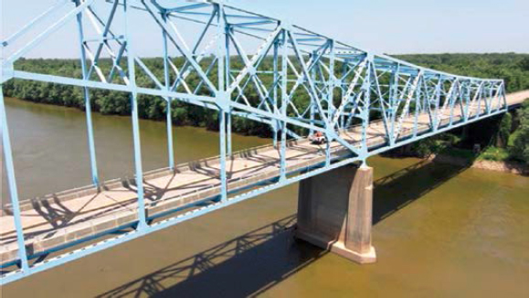
The two parallel structures of Bridge 1 carry I-75 over a creek, as shown in Figure 1. The identical three-span structures are 525 ft long and were selected because of their steel open multi-girder
Table 2. NBIS elements inspected at selected sites.
| Bridge Element (Number) | Bridge 1 | Bridges 2 and 3 | Bridges 4, 5, and 6 | Bridges 7 and 8 | Bridges 9, 10, and 11 | Bridge 12 | Bridges 13 and 14 | Bridges 15 and 16 | Bridges 17 and 18 | Bridges 19 and 20 | Bridge 21 | Bridge 22 |
|---|---|---|---|---|---|---|---|---|---|---|---|---|
| RC Deck (12) | X | X | X | X | X | X | X | X | ||||
| Steel Deck Open Grid (28) | X | |||||||||||
| Timber Deck (31) | X | |||||||||||
| Other Slab (65) | X | |||||||||||
| Steel Box Girder (102) | X | |||||||||||
| PSC Box Girder (104) | X | |||||||||||
| Steel Girder Beam (107) | X | X | X | X | X | X | X | X | ||||
| PSC Girder Beam (109) | X | X | X | |||||||||
| RC Girder Beam (110) | X | |||||||||||
| Timber Girder Beam (111) | X | |||||||||||
| Steel Stringer (113) | X | X | X | X | ||||||||
| Steel Truss (120) | X | X | X | X | X | |||||||
| Steel Arch (141) | X | |||||||||||
| Main Cable (147) | X | X | X | |||||||||
| Secondary Steel Cables (148) | X | X | ||||||||||
| Steel Floor Beam (152) | X | X | X | X | X | X | ||||||
| Pin and/or Pin and Hanger Assembly (161) | X | X | X | |||||||||
| Steel Gusset Plate (162) | X | X | X | X | ||||||||
| RC Column (205) | X | X | X | X | X | X | ||||||
| Timber Column (206) | X | |||||||||||
| Steel Column Tower (207) | X | |||||||||||
| RC Pier Wall (210) | X | X | X | |||||||||
| Masonry Wall Pier (213) | X | |||||||||||
| RC Abutment (215) | X | X | ||||||||||
| Timber Abutment (216) | X | |||||||||||
| Masonry Abutment (217) | X | |||||||||||
| RC Pile Cap (220) | X | |||||||||||
| RC Pier Cap (234) | X | X | X | X | X | X | ||||||
| Timber Pier Cap (235) | X | |||||||||||
| Strip Seal Expansion Joint (300) | X | |||||||||||
| Compression Joint Seal (302) | X | |||||||||||
| Modular Joint (303) | X | |||||||||||
| Open Expansion Joint (304) | X | |||||||||||
| Moveable Bearing (311) | X | X | X | X | X | X | ||||||
| Fixed Bearing (313) | X | X | ||||||||||
| Pot Bearings (314) | X | |||||||||||
| Other Bearing (316) | X | X | ||||||||||
| Metal Bridge Railing (330) | X | |||||||||||
| RC Bridge Railing (331) | X | X | X | X | X | X | X | |||||
| Timber Bridge Railing (332) | X | |||||||||||
| Wearing Surfaces (510) | X | X | X | |||||||||
| Steel Protective Coatings (515) | X | X | X | X | X | X | ||||||
| Concrete Protective Coatings (521) | X | |||||||||||
| Drainage | X | X | X | X | ||||||||
| Luminaires | X | |||||||||||
| RC Diaphragms | X | |||||||||||
| Steel Slider Bearings | X |
| Bridge Element (Number) | Bridge 1 | Bridges 2 and 3 | Bridges 4, 5, and 6 | Bridges 7 and 8 | Bridges 9, 10, and 11 | Bridge 12 | Bridges 13 and 14 | Bridges 15 and 16 | Bridges 17 and 18 | Bridges 19 and 20 | Bridge 21 | Bridge 22 |
|---|---|---|---|---|---|---|---|---|---|---|---|---|
| Wind Cowl | X | |||||||||||
| Navigation Lights | X | X | ||||||||||
| Sheave and Trunnion Bearings | X | |||||||||||
| Lift Track | X | |||||||||||
| Dolphins | X |
NOTE: PSC = prestressed concrete; RC = reinforced concrete.
superstructure (one of the most common systems in the national bridge inventory). The structure has common details prone to fatigue and constraint-induced fracture, with known fractures monitored quarterly with a UBIT. The site was safely accessed by mobilizing from behind the roadway barrier and walking under the bridge. The weather on the day of the inspection was sunny, 60°F, with mild winds.
2.3.2 Bridges 2 and 3
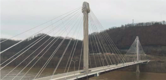
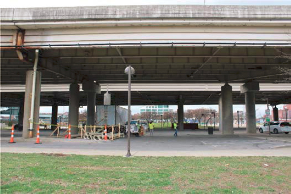
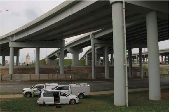
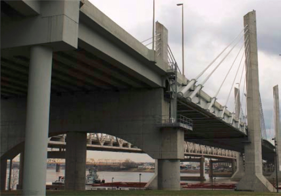
Bridge 2 is the 2,155-ft-long main span of a structure that carries a U.S. highway over a major river. Bridge 3 comprises the approach spans. These structures were selected because of their converging cable-stayed main span, weathering steel open girder superstructure, and prestressed concrete open multi-girder approach spans. The main span is shown in Figure 2, and the undersides of the approach and main span are shown in Figure 3. The main span towers are post-tensioned at the top and along the mid-height cap. This structure exhibits cracks in the high-density polyethylene (HDPE) stay pipes, slackening steel wind ties, and shear cracking through the prestressed concrete girders. The undersides of the main and approach spans were easily accessed from the ground, and the bridge tower and cables above the deck were accessed from the wide shoulders on the main span. The weather on the day of the inspection was partly cloudy to overcast and 60°F, with mild winds.
2.3.3 Bridges 4, 5, and 6
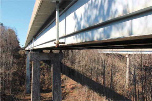
Bridges 4, 5, and 6 carry a state road over a major river. This structure was selected because the three-span, 1,918-ft-long cantilevered through truss (Bridge 4) includes rolled and welded truss members with known global distortions of members and gusset plates, as shown in Figure 4. The main suspended span also has a pin and hanger system. Bridge 5 encompasses the 494-ft-long approach spans, which consist of four spans of steel I-girders. Bridge 6 includes the seven approach spans, which are 579 ft long and consist of prestressed concrete I-girders, as shown in
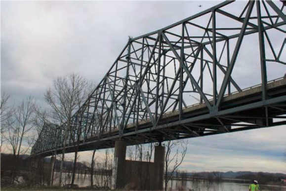
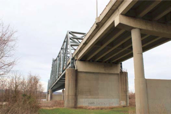
Figure 5. The underside of the approach spans and the exterior of the main span were accessed from the ground adjacent to the structure. The weather on the day of the inspection was partly cloudy to overcast and 70°F, with mild winds.
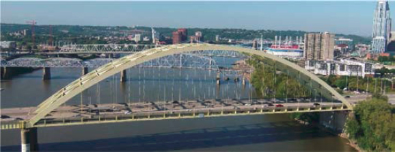
2.3.4 Bridges 7 and 8
Bridges 7 and 8 carry an interstate over a major river. Bridge 7, the 758-ft-long main span shown in Figure 6, is a steel through arch with known section loss on the main span cables. Bridge 8, the multiple approach spans shown in Figure 7, consists of two parallel structures with

steel open multi-girder systems that exhibit known cracking and corrosion. This structure was selected because the UAS form factors could be tested between two adjacent structures with a shallower beam depth than other selected structures, and the research team had experience conducting Routine and Fracture-Critical Inspections of the structure. The weather on the day of the inspection was sunny and 50°F, with mild winds.
2.3.5 Bridges 9, 10, and 11
Bridges 9, 10, and 11 carry a state road over a major river. This structure, shown in Figure 8, was chosen because it is a historic suspension bridge with main and secondary suspension cables, a riveted built-up lacing bar stiffening truss, an open steel grid deck, and masonry towers. Deficiencies on the 1,057-ft-long main span elements included severed wires in the cables, cracked eye bars, and efflorescence, spalling, and cracking on the masonry pier and abutment. Bridge 9 was the main and tail spans, Bridge 10 was a built-up plate girder approach span, and Bridge 11 was a masonry tunnel approach span. The main, tail, and approach spans were accessible from the ground and from sidewalks on the structure, which was closed to traffic. The weather on the day of the inspection was sunny to partly cloudy or overcast and about 60°F, with mild winds.
2.3.6 Bridge 12
Bridge 12 carries a state road over a major river, as shown in Figure 9. This structure was selected because the hanger sections of the steel through truss tied arch are riveted built-up sections rather
than traditional cables. The truss also has known gusset plate distortion from pack rust and section loss. Additionally, the overhead truss presents a challenge for UAS operation because of magnetic interference. The concrete pier wall and railing differ from other selected structures, and the approach spans have different girder and diaphragm configurations. Access was provided while the bridge was closed for a rehabilitation inspection. The weather on the day of the inspection was sunny and 100°F.
2.3.7 Bridges 13 and 14
Bridges 13 and 14 are two separate spans of a structure that carries interstate highways through an urban area. This 2,073-ft-long multi-span bridge was selected because it is a steel open multi-girder structure with pin and hanger systems, as shown in Figure 10, and has more than 15 fatigue-prone details with cracking. There is also extensive section loss at the pin and hanger connections and spalling and exposed rebar on the concrete columns. The structure was accessible from the ground below and between the two parallel structures. The weather on the day of the inspection was overcast and about 60°F, with high winds.
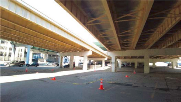
2.3.8 Bridges 15 and 16
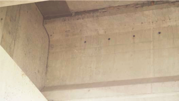
The three spans of Bridges 15 and 16 carry an interstate over surface streets in an urban area. These structures were chosen because they have both steel box girders (Bridge 15) and prestressed concrete closed web girders (Bridge 16), with variable spacing and stay-in-place forms, as shown in Figure 11 and Figure 12, respectively. The structures were accessible from the ground below. The weather on the day of the inspection was overcast and about 60°F, with moderate winds.
2.3.9 Bridges 17 and 18
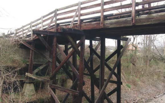
Bridges 17 and 18 are two 95- to 120-ft-long timber structures that carry rural roads over a railroad. These structures were chosen because complex timber superstructures are uncommon in the national bridge inventory. The dark color and stratifications of the timber tested the UAS sensor’s ability to adapt to environmental conditions. A portion of Bridge 17 is shown in Figure 13. The two structures also have common timber deficiencies such as splits, checks, and cracking. These structures were easily accessible from the ground adjacent to the structure. The weather on the day of the inspection was overcast and about 60°F, with mild winds.
2.3.10 Bridges 19 and 20
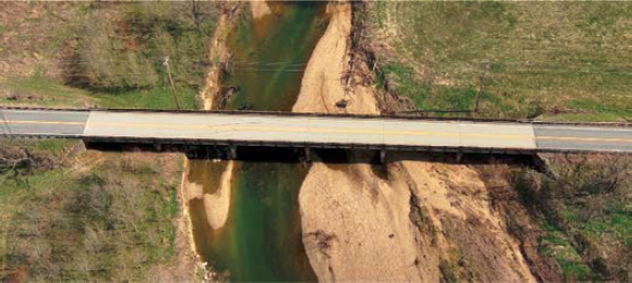
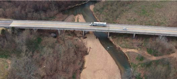
Bridges 19 and 20 are two separate structures that carry a state road and a U.S. highway, respectively, over a creek. Bridge 19 is a six-span, 318-ft-long reinforced concrete T-beam bridge, shown in Figure 14. Bridge 20 is an eight-span, 766 ft-long prestressed concrete I-girder bridge, shown in Figure 15. These structures were chosen for their known scour deficiencies, which affect the substructure elements. Inspecting these structures demonstrated the ability of the UAS to inspect substructure elements and adjacent channels, including scour levels, settlement, and abrasion. These structures were easily accessible from the ground between the two structures. The weather on the day of the inspection was sunny and about 70°F, with mild winds.
2.3.11 Bridge 21
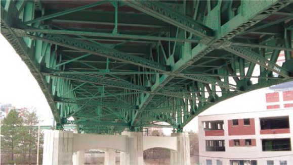
Bridge 21 carries a U.S. highway over local streets in an urban area. This deck truss comprises riveted built-up steel members with a reinforced concrete deck, as shown in Figure 16. The structure was selected because the closely spaced members tested the obstacle avoidance capabilities of the UAS when it was flying inside the truss but not over traffic. The bridge was easily accessed from a parking lot below the structure. The weather on the day of the inspection was overcast and about 60°F, with mild winds.
2.3.12 Bridge 22
Bridge 22 is a lift bridge that carries a railroad over a major river. This structure was selected because of its complex lift mechanisms, which include cables, counterweights, trunnions, track guides, and sheaves. The main lift structure is a steel truss of riveted built-up members with known
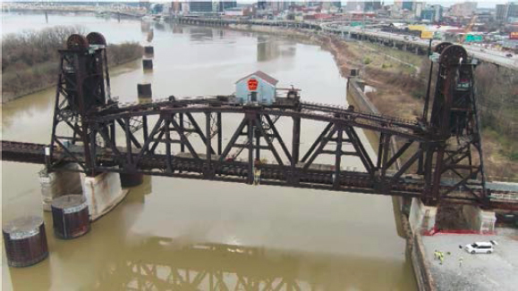
corrosion, section loss, and deteriorated protective coatings, as shown in Figure 17. The immediately adjacent approach spans were built-up riveted plate girders. The bridge was accessible from below and from an adjacent lot, and with direct coordination with the lift operator. This bridge was in a controlled airspace, and FAA authorization was required to fly UAS. The weather on the day of the inspection was overcast and about 60°F, with mild winds.
2.4 UAS Form Factors
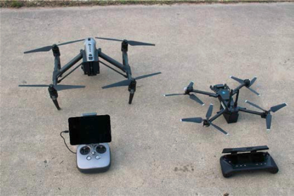
Of the many types of UAS that exist for visual data collection, multi-rotor aircraft are most used for bridge inspections. Two models of multi-rotor aircraft were used in this research, representing two classes of commercially available UAS: Form Factor 1 (FF1) and Form Factor 2 (FF2). Briefly, FF1 UAS are designated as those with attached (not interchangeable) cameras and a compact size, whereas FF2 UAS have interchangeable cameras and a more moderate size. The specifications for the two UAS are given in Table 3. Both airframes are shown side by side in Figure 18.
The FF1 was a smaller airframe (could be held in one hand) with advanced obstacle avoidance, a non-interchangeable camera, and single-operator controls. The single-operator controls did not allow a sensor operator to participate, which meant the remote pilot needed to focus simultaneously on the flight controls and the sensor settings. Because of its small size and the three levels of obstacle avoidance (standard at 34 in., close at 11 in., and minimal at 4 in.), the FF1 airframe was easier to navigate between bridge elements but more difficult to see at farther distances unless the strobe lights were activated. The airframe was also more susceptible to turbulence and wind gusts.
Table 3. Form Factor 1 and 2 UAS specifications.
| Form Factor 1 | Form Factor 2 | |
| Estimated Cost | $16,000 (sensor cost included) | $9,700 (+ $2,000 for sensor, + $300 for zoom lens) |
| Navigation Sensors | Forward/Backward/Upward/Downward/Sides True 360° Camera Navigation 6x cameras in trinocular configuration top and bottom | Front/Top/Bottom |
| Max. Wind Resistance | 25 mph | 27 mph |
| Operating Temps | 23°F to 104°F | −4°F to 104°F |
| Battery Life (stated) | 23 minutes | 25 minutes |
| Battery Life (field) | 19 minutes | 19 minutes |
| Camera Spec | Single sensor: 12-megapixel camera, 4K video at 60 fps. | Interchangeable payloads available: X5S Camera takes 20.8 MP stills and records 4K video. No thermal sensors available for this model. |
| Sensor Size | 1/2.3-in. 12.3 MP CMOS | 4/3-in. CMOS |
| Gimbal Range | Pitch: −110° to +45° Demo permissions for pitch: −110° to +90° | Multiple sensors could be used/interchangeable Free range of motion Pitch: −130° to +40° Roll: ±20° Pan: ±320° |
| Video Specs/Options | 3840x2160 30 fps, 3840x2160 60 fps, 3840x2160 48 fps, 3840x2160 24 fps, 1920x1080 120 fps, 1920x1080 60 fps, 1920x1080 30 fps | 5.2K 30 fps, 4K 60 fps |
| Photo Specs/Options | 12 MP HDR photos | X5S = 15 mm—20.8 MP still |
| Zoom | Yes | No: X5S Yes: X5S sensor w/Panasonic Lumix 14–42 mm lens |
| GPS On/Off | Yes | Yes |
| Obstacle Avoidance | High | Low |
| Sensor Operator-Enabled | No | Yes |
| Interchangeable Payload | No | Yes |
| External Lighting | Not available | Available |
| Adjustable Exposure | Yes | Yes |
| Thermal | No | No |
| Country of Origin | USA | China |
| Portability | High | Low |
| Prop Guards | Not available | Available |
NOTE: CMOS = complementary metal oxide semiconductor; 4K = 4,000 horizontal pixels (high resolution); fps = frames per second; HDR = high dynamic range; MP = megapixel.
This FF1 is compliant with the National Defense Authorization Act (NDAA) but is not listed on the Blue sUAS list. However, a different version of this FF1, with the same body style, was listed. Its capabilities are different than those of the non-NDAA-compliant version.
The FF2 was a larger airframe with an interchangeable camera and dual operator control capabilities. The dual controls meant a sensor operator could participate and split the inspection workflow with the remote pilot. Because of its larger size, the FF2 airframe was flown at an offset to the bridge elements but was more visible to the remote pilot and was less susceptible
to turbulence and wind gusts. This FF2 is not listed on the Blue sUAS list and has not indicated NDAA compliance as of the writing of this report.
2.5 UAS Flight Operations
Inspecting portions of the selected structures with UAS required initial planning, documentation, and review before the UAS could be safely flown at each site. In-office preparations were taken to identify and mitigate risks at each site. Once the remote pilots were on site, operations included a pre-flight checklist, an operations review with on-site personnel, sensor calibration, inspections of the structure and particular elements, and post-flight data review and management. This methodology and the lessons learned were documented throughout the inspection and incorporated into the guidelines for UAS inspections.
2.5.1 Preparing for the Inspections
Preparations for conducting the UAS inspections as part of the research included documenting the remote pilot qualifications, obtaining permission to access the bridge sites and use UAS, and reviewing the previous inspection reports. The specific remote pilot qualifications were documented for consideration in developing the guidelines and training. The remote pilot’s qualifications included logged inspection flight hours, logged flight hours with the specific UAS form factors, and the comfort level and familiarity of flying a UAS. The logged hours of the crew members who conducted the inspections are given in Table 4.
Before conducting the UAS inspections, it was necessary to prepare the required permits, applications, notifications, equipment, and traffic control. This included obtaining permission from the bridge owner and from the FAA through an approved LAANC (Low Altitude Authorization and Notification Capability) provider. In one case, authorization was needed from the UAS manufacturer to operate in a manufacturer-restricted area near an airport, but this was not discovered until on site. Full lane closures were not needed because the remote pilot gathered sufficient video and imagery from the outboard side of the bridges for the structure types and elements inspected. This helped each inspection minimize the impacts to traffic and use time efficiently.
If inspection reports were available, the on-site team leader reviewed the reports to determine elements to be inspected, areas of deficiencies, and any areas with restricted access. This provided
Table 4. UAS crew members’ logged flight hours.
| Crew Member 1 | Crew Member 2 | Crew Member 3 | Crew Member 4 | Crew Member 5 | |
| Years with Part 107 UAS certification | 5.5 | 4.5 | 4.5 | n/a | n/a |
| Logged hours for inspection-type flying | 130 | 85 | 105 | 0 | 0 |
| Total logged hours | 170 | 90 | 115 | 0 | 0 |
| Logged hours on FF2 | 80 | 45 | 32 | 0 | 0 |
| Logged hours on FF1 | 2 | 0 | 0 | 0 | 0 |
| Years of inspection experience | 4 | 12 | 30 | 3 | 0.5 |
| Level of comfort with UAS technology | High | Medium | High | Low | Low |
NOTE: n/a = not applicable.
the team with awareness of defect locations when performing detection calibration on-site. Not all defect locations were shared with the entire team, though, to verify that the inspector could identify defects during flight or during the post-flight data review. A binary (yes/no) assessment for defect detection was also performed to determine whether the UAS form factors could capture enough detail for the inspector to view and access common deficiencies.
2.5.2 Conducting Inspections
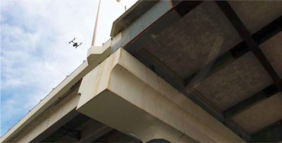
UAS operations at each site consisted of an initial safety briefing, pre-flight inspections, and a checklist review, followed by detection calibrations and inspection flights, and ended with data collection and review. The pre-flight inspections and setup took about 5–10 minutes but were not necessary if the bridges inspected on the same day were nearby. To calibrate the detection capability of the remote pilot and sensor, the remote pilot first flew each UAS to a known hairline crack in a concrete element to verify that the deficiency could be detected. Examples of the detection calibration flights for the two form factors are shown in Figure 19 and Figure 20. The cracks used were either 0.004 in. or 0.012 in. wide, representing the transition from CS1 to CS2 for cracking in prestressed or reinforced concrete elements, respectively. A crack width gauge card was used if a known defect was not available, as shown in Figure 21. The UAS was then
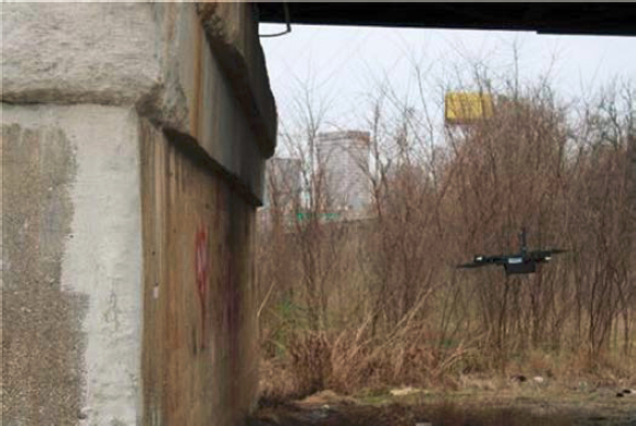
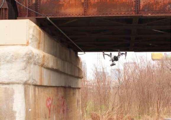
flown at increasing standoff distances while the camera settings were adjusted to determine the maximum standoff distance for detecting the chosen hairline crack. The cracks were viewed in various lighting conditions if possible. It was assumed that other concrete and steel deficiencies (spalling, exposed rebar, corrosion, section loss) would also be observable if the UAS were flown at or below the maximum standoff distance. This initial calibration also determined the necessary camera adjustments to account for the environmental conditions and sensor characteristics. In this report, snapshots from the recorded UAS video and imagery, such as Figure 21, are shown at a lower resolution than at which the video was recorded.
After sensor calibration was completed at each site, inspection flights with the two UAS form factors were completed for the elements identified in Section 2.3. In all cases, only portions of the elements were inspected, as the intent was to evaluate the capabilities of the UAS and the ability of the inspector to gather adequate data, rather than to complete an inspection of the entire structure. The flight operations used to inspect specific groups of bridge elements are given in Tables 5 through 9, along with the traditional inspection procedures for comparison. The UAS inspection procedures noted in the tables vary slightly for the different form factors but are generalized in
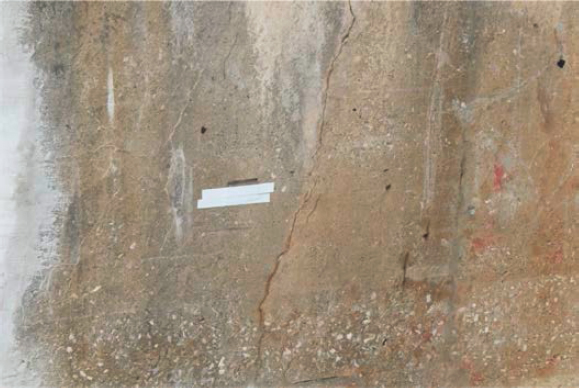
Table 5. Inspection procedures for bridge deck elements.
| Bridge Element (Number) | UAS Inspection Procedure | Non-UAS Inspection Procedure |
|---|---|---|
| RC Deck (12) | Offset flights above the top of the deck and inline flights through individual girder bays to capture the deck soffit. | Walk-through inspection of the top of the deck with visual observation from the shoulders of the roadway. Sounding of suspected areas of delaminated concrete with hand tools. Telescopic-aided visual observation of the deck soffit from the ground. |
| Steel Deck Open Grid (28) | Offset flights above the top of the deck and inline flights through individual girder bays to capture the deck soffit. | Walk-through inspection of the top of the deck with visual observation from the shoulders of the roadway. Telescopic-aided visual observation of the deck soffit from the ground. |
| Timber Deck (31) | Offset flights above the top of the deck and inline flights through individual girder bays to capture the deck soffit. | Walk-through inspection of the top of the deck with visual observation from the shoulders of the roadway. Telescopic-aided visual observation of the deck soffit from the ground. |
| Other Slab (65) | Offset flights above the top of the deck and inline flights through individual girder bays to capture the deck soffit. | Walk-through inspection of the top of the deck with visual observation from the shoulders of the roadway. Sounding of suspected areas of delaminated concrete with hand tools. Telescopic-aided visual observation of the deck soffit from the ground. |
| Strip Seal Expansion Joint (300) | Offset flights above the deck. | Visual observation from the top of the deck. |
| Compression Joint Seal (302) | Offset flights using the gimbal to scan across the element. | Inspected concurrently with the walk-through inspection of the top surface of the deck and by telescopic-aided visual observation from the ground. |
| Modular Joint (303) | Offset horizontal flights along each face of the element or concurrent with the top side of the bridge deck. | Visual observation from the top of the deck, from a UBIT beneath the joint, or both. |
| Open Expansion Joint (304) | Offset flights above the deck. | Visual observation from the top of the deck. |
| Metal Bridge Railing (330) | Offset horizontal flights for each face of the element. | Visual observation from the top of the deck. |
| RC Bridge Railing (331) | Offset horizontal flights for each face of the element or offset flights above the deck. | Visual observation from the top of the deck. |
| Timber Bridge Railing (332) | Offset flights above the deck. | Visual observation from the top of the deck. |
Table 6. Inspection procedures for bridge superstructure elements.
| Bridge Element | UAS Inspection Procedure | Non-UAS Inspection Procedure |
|---|---|---|
| Steel Box Girder (102) | Inline flights for each face of the web and the lower face of the lower flange of all beams. | Telescopic-aided visual observation from the ground. |
| PSC Box Girder (104) | Inline flights for each face of the web and the lower face of the lower flange of all beams. | Telescopic-aided visual observation from the ground. |
| Steel Girder Beam (107) | Inline flights of each face of the web and the lower face of the lower flanges of all beams, with additional still photographs taken of details that require enhanced visual inspection techniques. | Telescopic-aided visual observation from the ground, a UBIT, or both. |
| PSC Girder Beam (109) | Inline flights for each face of the web and the lower face of the lower flange of all beams. | Telescopic-aided visual observation from the ground. |
| RC Girder Beam (110) | Inline flights for each face of the web and the lower face of the lower flange of all beams. | Telescopic-aided visual observation from the ground. |
| Timber Girder Beam (111) | Inline flights for each face of the web and lower face of all beams. | Telescopic-aided visual observation from the ground. |
| Steel Stringer (113) | Inline flights for each face of the web and the lower face of the lower flange of all beams. | Visual observation from the ground, catwalks, a UBIT, or any combination of the three. |
| Steel Truss (120) | Two offset flights along each outboard face of individual members from two angles to obtain a hemispherical 270-degree view. | Telescopic-aided visual inspection from the ground, catwalks, the top of the deck, or any combination of the three. |
| Steel Arch (141) | Inline flights of the arch ribs from the outboard face of the element, with the inboard face of the opposite arch line inspected concurrently. | Telescopic-aided visual observation from the deck. |
| Main Cable (147) | Offset flights along each outboard face of individual members or offset vertical flights along each face of the element. | Telescopic-aided visual observation from the deck. |
| Secondary Steel Cables (148) | Offset flights along each outboard face of individual members. | Telescopic-aided visual inspection from the ground and the top of the deck. |
| Steel Floor Beam (152) | Inline flights for each face of the web and the lower face of the lower flange of all beams. | Visual observation from the ground and catwalks. |
| Pin and/or Pin and Hanger Assembly (161) | Offset flights with hemispherical flight patterns on inboard and outboard faces of each assembly. | Telescopic-aided visual inspection from the ground and the top of the deck. |
| Steel Gusset Plate (162) | Offset flights with hemispherical flight patterns on inboard and outboard faces of each location. | Telescopic-aided visual inspection from the ground, catwalks, and the top of the deck. |
NOTE: PSC = prestressed concrete; RC = reinforced concrete.
Table 7. Inspection procedures for bridge substructure elements.
| Bridge Element | UAS Inspection Procedure | Non-UAS Inspection Procedure |
|---|---|---|
| RC Column (205) | Offset vertical flights for each face of the element. | Telescopic-aided visual observation from the ground, UBIT, or both. Probe as necessary for scour concerns. |
| Timber Column (206) | Offset vertical flights for each face of the element. | Telescopic-aided visual observation from the ground, with sounding by a hammer or line rode in accessible areas. |
| RC Pier Wall (210) | Offset vertical or horizontal flights for each face of the element. | Telescopic-aided visual inspection from the ground. Probe as necessary for scour concerns. |
| Masonry Pier Wall (213) | Offset vertical flights for each face of the element. | Telescopic-aided visual observation from the ground. Probe as necessary for scour concerns. |
| RC Abutment (215) | Offset horizontal flights for each face of the element. | Visual observation from the ground. |
| Timber Abutment (216) | Offset horizontal flights for each face of the element. | Visual observation from the ground. |
| Masonry Abutment (217) | Offset vertical flights for each face of the element. | Visual observation of all visible surfaces from the ground, with sounding of piles by hammer or line rode in accessible areas. |
| RC Pile Cap (220) | Offset horizontal flights for each face of the element. | Visual observation from the ground. |
| RC Pier Cap (234) | Offset horizontal flights along each face of the element. | Telescopic-aided visual observation from the ground, UBIT, or both. |
| Timber Pier Cap (235) | Offset horizontal flights for each face of the element. | Telescopic-aided visual observation from the ground. |
NOTE: RC = reinforced concrete.
Table 8. Inspection procedures for bridge-bearing and wearing surface elements.
| Bridge Element | UAS Inspection Procedure | Non-UAS Inspection Procedure |
|---|---|---|
| Moveable Bearing (311) | Offset hovering flights for individual elements. | Telescopic-aided visual observation from the ground. |
| Fixed Bearing (313) | Offset hovering flights for individual elements. | Telescopic-aided visual observation from the ground. |
| Pot Bearings (314) | Offset hovering flights for individual elements. | Telescopic-aided visual observation from the ground. |
| Other Bearing (316) | Offset hovering flights for individual elements. | Telescopic-aided visual observation from the ground. |
| Wearing Surfaces (510) | Offset flights above the deck or concurrent with the top of the deck. | Visual observation from the top of the deck or inspected concurrently with the walk-through inspection of the deck. |
| Steel Protective Coatings (515) | Inspected concurrently with the inspection of individual elements. | Inspected concurrently with the inspection of individual elements. |
| Concrete Protective Coatings (521) | Inspected concurrently with the inspection of individual elements. | Inspected concurrently with the inspection of individual elements. |
Table 9. Inspection procedures for miscellaneous bridge components.
| Bridge Element | UAS Inspection Procedure | Non-UAS Inspection Procedure |
|---|---|---|
| Deck Drainage | Inspected during the above- and below-deck inspections. | Inspected as part of the walk-through inspection of top surface of the deck. Lower drainage pipe extensions inspected by telescopic-aided visual observation from the ground, UBIT, or both. |
| Luminaires | Inspected concurrently with the inspections of the fascia girder beam. | Visual observation from the ground, the top of the deck, UBIT, or both. |
| RC Diaphragms | Inspected concurrently with the inspections of the PSC girders. | Telescopic-aided visual observation from the ground. |
| Steel Slider Bearings | Offset hovering flights for each element. | Visual observation from a UBIT. |
| Wind Cowl | Offset horizontal flights for the outboard face of the element. | Visual observation from a UBIT. |
| Navigation Lights | Inspected concurrently with inspection of the superstructure and deck. | Visual observation from the ground and the top of the deck. |
NOTE: PSC = prestressed concrete; RC = reinforced concrete.
the tables to compare the UAS method with traditional inspection techniques. For the purposes of this comparison, traditional Routine Inspection methods were used as a baseline, as UAS will most likely be used for visual inspections that take place during a Routine Inspection. In-depth and Fracture-Critical Inspections may also benefit from UAS, but the current hands-on and arm’s length requirements for performing these inspections mean UAS will likely be most applicable to Routine Inspections.
In addition to the Routine Inspection flights, two automated mapping flights were conducted at the scour-critical bridges to collect imagery of the structures, channels, and surrounding terrain. The intent was to use this imagery to create orthomosaics and 3-D models covering a large area to document the channel and scour effects. With the FF2 airframe, the flight path and image capture were automated using the available functions of the UAS. With the FF1 airframe, the flight path and image capture were performed manually.
After the inspection flights were performed, the data was downloaded from the UAS to two solid-state drives for storage and backup. Once downloaded, the files were renamed on the basis of the main elements visible in the video, but the files could have also been named on the basis of the span number or plan information. The video and imagery data were then reviewed on site on a larger screen to verify the inspection results and the quality of the recorded imagery, as shown in Figure 22. This post-flight review was undertaken because the resolution of the UAS controller’s screen was lower than the recorded imagery, and an in-depth inspection could be performed immediately if any critical deficiencies were discovered.
2.5.3 Data Processing
The focus of the data processing and review was first to determine which elements were visible in the recorded imagery and then to rank each from the element’s accessibility, the sensor’s adaptability, and the remote pilot’s comfort. In addition to performing this review, the research team selected videos from three bridge sites and sent each to three inspectors to perform a desktop review. A sample of still images and videos from one site was also sent to two firms specializing in AI-based detection to evaluate how their models performed using the UAS-collected imagery.
The initial in-depth review of the data ranked element accessibility, sensor adaptability, and remote pilot comfort on a scale of 1–3 using the rubric given in Table 10, with the results given in
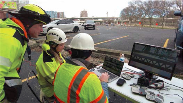
Table 10. Rubric for element and deficiency detectability.
| Element Accessibility | Sensor Adaptability | Remote Pilot Comfort | |
| 3 | The element is unobstructed within the field of view. All aspects of the element can be viewed in one or more recorded inspection videos/still images (for example, if the interior and exterior of a girder were both inspected but saved in separate video files because of workflow or equipment constraints). | The sensor’s exposure/focus could be adjusted to produce an acceptable image of the entire element within the field of view. | The remote pilot was completely comfortable in flight and in control of the UAS. No erratic/unpredictable airframe behavior caused by magnetic interference, wind, GPS connection, etc. Position of the UAS was in a safe place (for example, over land, no obstacles) and easily maneuvered by the remote pilot. |
| 2 | The element is partially obstructed within the field of view. Minor aspects of the element cannot be viewed in any recorded inspection videos/still images (for example, the top of the bottom flange is not visible, there are other attachments/utilities, vegetation covers the element). | The sensor’s exposure/focus could be adjusted to produce an acceptable image of much of the element within the field of view. | The remote pilot was mostly comfortable in flight and in control of the UAS. Possible mild unpredictable airframe behavior caused by magnetic interference, wind, GPS connection, etc. Position of the UAS was in a safe place (for example, over land, no obstacles) and easily maneuvered by the remote pilot. |
| 1 | The element is substantially obstructed within the field of view. Most of an element cannot be viewed in any recorded inspection videos/still images (for example, if only the edges and top side of a deck joint are visible, only one side of a floor beam can be viewed). | The sensor’s exposure/focus could be adjusted to produce an acceptable image of only minimal aspects of the element within the field of view. | The remote pilot was mildly uncomfortable in flight and with control of the UAS. The remote pilot may experience unpredictable airframe behavior caused by magnetic interference, wind, GPS connection, etc. Position of the UAS was in a risky place (for example, over water, near tree branches), but the remote pilot could still maneuver. |
| 0 | The element is completely obstructed within the field of view. No aspects of the element are visible in any recorded inspection videos/still images. | The sensor’s exposure/focus could not be adjusted to produce an acceptable image of the element within the field of view. | The remote pilot was uncomfortable in flight and with uncertain control of the UAS. The remote pilot experienced unpredictable airframe behavior caused by magnetic interference, wind, GPS connection, etc. Position of the UAS was in a risky place (for example, over water, near tree branches) and maneuverability was in question by the remote pilot. |
Appendix B. Element accessibility considered the visibility of the elements and whether there were any obstructions from elements or the limitations of the UAS. Sensor adaptability considered how the camera and lens settings were adjusted to account for environmental conditions such as low or diffuse light, harsh shadows, or the transition from full sun to shade. The ranking for remote pilot comfort was more subjective and was affected by the GPS connection, wind gusts and turbulence, and the airframe’s flight characteristics. Ratings were performed for most elements visible in the recorded videos from each bridge site. Any deficiencies were also noted on a yes/no scale, but the quantities of deficiencies or condition states were not determined during this review. A subsequent review of select videos performed by other unaffiliated inspectors did determine quantities of deficiencies and condition states.
In this subsequent review, select videos from three sites (Bridge 3, Bridges 13 and 14, and Bridges 15 and 16) were sent to three inspectors to perform a desktop review. The intent of this review was to evaluate the use of UAS-collected video and imagery in an inspection for which the inspector was not present when the imagery was collected (in the office, rather than in the field). The three bridge inspectors who received the inspection data had a broad range of experience, as shown in Table 11. After receiving the videos, the reviewers were asked to quantify the condition states of the major bridge elements, provide comments on the quality of the imagery, and share any perceived limitations to incorporating the imagery into an inspection. The reviewers were not provided with the most recent inspection report, and they were not advised on what defects to look for. Although the videos were sent to multiple inspectors, the variability of assigned deficiencies or condition states among the three inspectors was not quantified.
In addition to the desktop review, a small sample of videos and still images was sent to two firms claiming specialization in AI inspection. The intent of this review was to evaluate the incorporation of current commercially available AI detection programs into a bridge inspection using UAS-collected imagery. Both companies represent the most current advances in AI technology for their specific applications and provide a wide range of infrastructure inspection services. The imagery shared with the two firms consisted solely of the prestressed concrete girders with known cracking at Bridge 3, shown in Figure 23. This data was selected because most AI models for structural applications are trained and focused on crack detection in concrete materials. The findings of the AI inspection are presented in the following chapter.
Table 11. Desktop reviewers’ experience and qualifications.
| Inspector No. | Job Title | Experience |
|---|---|---|
| 1 | Program Administrator | Professional engineer and team leader with 25 years of inspection and program management experience (but has not performed inspections in 10 years), no UAS flight experience |
| 2 | Senior Team Leader | Certified bridge inspector with 13 years of inspection experience on complex and conventional bridges, no UAS flight experience |
| 3 | Junior Inspector | Professional engineer and certified bridge inspector with FAA Part 107 certification, 5 years of experience (2 years being inspection experience) |