Uncrewed Aerial Systems Applications for Bridge Inspections: Element-Level Bridge Data Collection (2024)
Chapter: 3 Findings and Applications
CHAPTER 3
Findings and Applications
3.1 Flight Operations
After inspections of the selected structures were completed, it was apparent that the two UAS form factors both had certain limitations that would affect how they would be used in a routine bridge inspection with element-level data collection. The major differences were the size and stability of the airframe and the characteristics of the sensor. Briefly, the smaller FF1 airframe was able to access more areas of each structure but was less stable than the larger FF2 airframe. The sensor controls of the FF2 airframe were easier to adjust, and the higher-quality zoom lens meant the airframe could fly at a greater standoff distance while collecting adequate video and imagery. The approximate maximum standoff distance was determined on the basis of initial calibration flights, with the results shown in Table 12. Both airframes (and UAS for bridge inspections in general) could be considered as another tool available to inspectors, to be used when the selected UAS improves the quality, safety, or efficiency of the inspection.
3.1.1 Form Factor 1 UAS
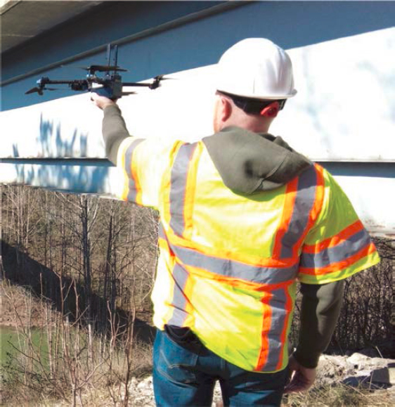
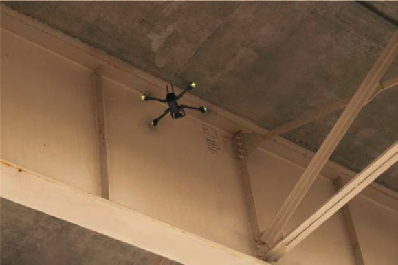
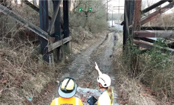
Because of its small size, the FF1 airframe could be launched and landed by hand, as shown in Figure 24, which was beneficial at bridge sites with steep embankments, such as at Bridge 1. At most bridge sites, though, the airframe was launched from the ground, taking care to avoid interference with traffic or cables once the UAS was airborne. In a few situations (at Bridge 4, Bridge 21, and Bridge 22), the aircraft was launched away from the truss structures or guardrails to avoid magnetic interference.
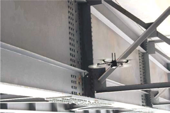
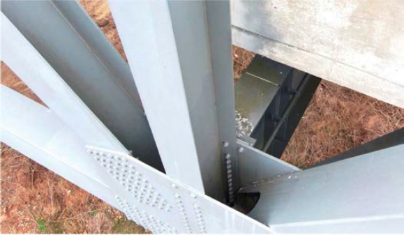
Once in flight, the advanced obstacle avoidance made constant adjustments to keep the airframe stable around exterior and interior bridge elements. These adjustments were less of a concern for the remote pilot when inspecting exterior elements (cables and connections, hangers, fascia girders) because there was enough space to fly the UAS at a farther standoff distance. However, when the remote pilot was inspecting interior elements, these adjustments were more discomforting because of the enclosed space and the perceived instability of the airframe. This was especially prevalent when the UAS was flying above the bottom flange and between the closely spaced girders on Bridge 1, as shown in Figure 25. At that site, the variability in how the proximity sensors detected the slender flanges and monolithic web caused the airframe to drift so closely toward the girders that the remote pilot was uncomfortable flying in that situation.
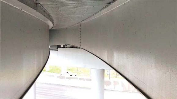
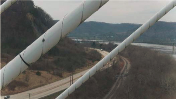
The perceived instability of the airframe when flying between girders was less pronounced when the girders were widely spaced (for example, on the Bridge 2 main span and Bridges 13 and 14). The UAS was also more stable when flying between prestressed I-girders and steel and prestressed concrete box girders, as shown in Figure 26, because of the larger planar surfaces and the visual sensors it uses for stabilization. When the airframe was above the bottom flange and between the
Table 12. Approximate maximum standoff distances.
| Defect | FF1 (12 MP, 4K at 60 fps) | FF2 (20.8 MP, 4K at 60 fps) | FF2 (zoom, 14–42 mm) |
|---|---|---|---|
| Reinforced concrete crack (0.012 in. threshold) | 10 ft | 10 ft | 30 ft |
| Prestressed concrete crack (0.003–0.004 in. threshold) | 5 ft | 10 ft | 20 ft |
| Steel crack (hairline) | 5 ft | 10 ft | 20 ft |
NOTE: fps = frames per second; 4K = 4,000 horizontal pixels (high resolution); MP = megapixel.
girders, it was simple to rotate the UAS to inspect individual bays, but cross frames, horizontal and vertical stiffeners, and wind bracing limited how far the airframe could fly longitudinally. The FF1 UAS was not flown through cross frames because the cross-frame members were closely spaced. A more realistic flight pattern for inspecting girder bays during a Routine Inspection would involve flying longitudinally along the bridge, slightly below the bottom flange of the girders, and with the camera angled upward. In this manner the deck soffit and most of the girder webs and flanges could be inspected, but the top of the bottom flange would not be visible. To view the top of the bottom flange, a remote pilot could make short periodic flights up into the girder bay as a spot check or to inspect a known defect.
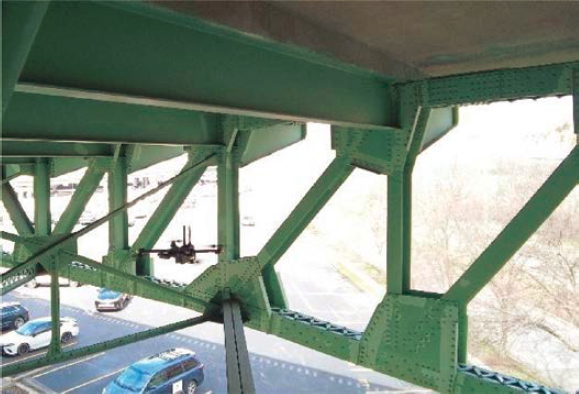
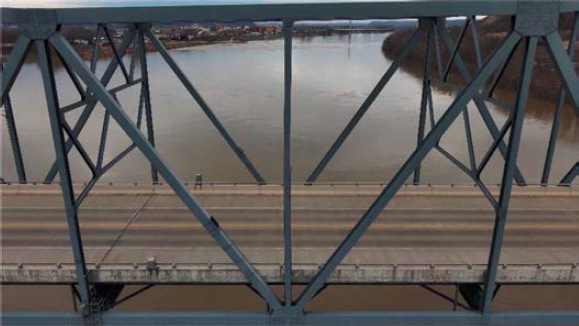
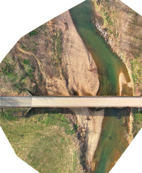
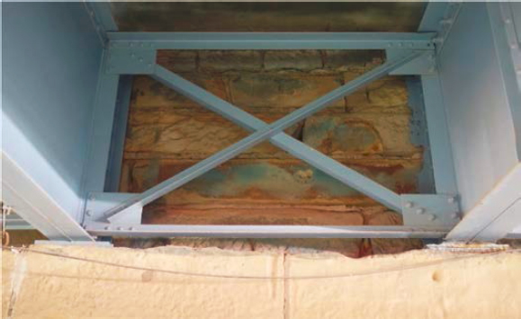
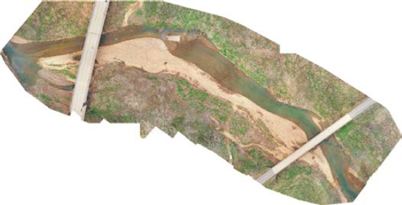
Although the FF1 airframe was not flown through cross-frame members, the UAS was flown between various truss members (at Bridge 4 and Bridge 21) without issue, as shown in Figure 27, to inspect the truss, deck soffit, floor beams, and stringer. The UAS also captured imagery of the interior of gusset plate connections, as shown in Figure 28, but not to the same level of detail as an arm’s length inspection. Since truss bridges tend to have multiple fracture-critical or non-redundant steel tension members that require an arm’s length inspection, a UAS such as the FF1 airframe would be more appropriate for global condition assessments. This could include inspecting for distortions of members, as shown in Figure 29, the condition of protective coatings and wearing surfaces, or the conditions of the channel and surrounding terrain. For example, the FF1 airframe was capable
of collecting adequate aerial photos, even when flown manually, to create an orthomosaic of one scour-critical bridge, as shown in Figure 30. A composite photo such as this would be beneficial to document the channel conditions and scour effects over time.
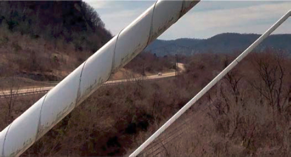
In most cases, it was possible to adjust the exposure and zoom settings for the sensor on the FF1 airframe to compensate for varying environmental conditions, but this was cumbersome. Because the FF1 airframe is a single-operator UAS, the remote pilot must also be the sensor operator, which requires frequently switching focus from flying the UAS to managing the sensor and collecting data. Furthermore, the settings for the camera exposure were not linked to a tactile function on the controller, but rather accessed through a menu on the controller’s touch screen. Although touchscreen menus require only a minor effort, this does require shifting the remote pilot’s focus away from flying. As will be seen, the dual controls of the FF2 airframe meant the remote pilot could concentrate on safely flying the UAS while the sensor operator controlled the data collection. While inspecting cables from the outboard side of the bridge (as on Bridge 2, Bridge 7, and Bridge 9), the remote pilot found that the zoom capabilities of the FF1 airframe were inadequate to view the inboard face of the cable on the opposite side of the bridge, shown in Figure 31. This meant a lane closure may have been necessary to inspect the inboard face of the cables, although this was not done as part of this project. External lighting attachments were not used because the FF1 airframe has a camera-based obstacle avoidance system. In addition, the UAS manufacturer recommended not using external lighting.
Regarding the observed deficiencies, the FF1 airframe captured sufficient imagery to identify most steel deficiencies like corrosion, distortion, and section loss but faced challenges identifying hairline cracking. For example, at Bridge 14, the FF1 airframe collected adequate imagery of nearly all deficiencies on the steel girders but had difficulty identifying known fatigue cracks near the top flange of a steel girder in the absence of markings left by a previous inspector. The FF1 airframe flying to collect imagery of a crack is shown in Figure 32, and a snapshot from the recorded video is shown in Figure 33. The UAS also identified cracking (down to 0.004 in.), spalls, delaminations, exposed rebar, corrosion, and efflorescence on concrete elements. On timber elements, common defects such as cracking, checks, splits, and section loss were visible but difficult to identify because of the dark color of the treated wood, linear shadows, and low illumination at the time of the inspection. Other deficiencies visible in the recorded imagery were corrosion and pitting of cables, cracked HDPE pipes, and slackening wind ties.
3.1.2 Form Factor 2 UAS
At most bridge sites, the FF2 airframe was launched and landed from the ground, the shoulder of the roadway, or the median. In a few cases the UAS was hand launched and landed, but this was more challenging because the airframe is larger than the FF1. The FF2 airframe was launched away from guardrails, metal structures, and vehicles to reduce magnetic interference. The internal compass was also recalibrated if the airframe was being launched at a new site more than 30 miles away from the previous site, which took 3–5 minutes.
The larger size of the FF2 airframe meant the UAS was more stable (less susceptible to vortex shedding and wind gusts) but needed to be flown farther from the bridge elements. For example, the wind speed on the day of the inspection at Bridge 13 and Bridge 14 was around 16 mph, greater than the wind speed at other sites. When flown in the open space between the two parallel structures, the FF1 UAS was very unstable from the up and down drafts caused by vortex shedding and was unable to fly between the structures. Conversely, the FF2 airframe was able to fly between the two structures and was stable even at the higher wind speeds. This was likely because the maximum wind resistance rating was higher on the FF2 UAS than on the FF1.
At Bridge 13, the FF2 UAS was able to fly above the bottom flange of the fascia girders when flown between the structures, which was typical at most sites. Fascia girders were typically inspected by
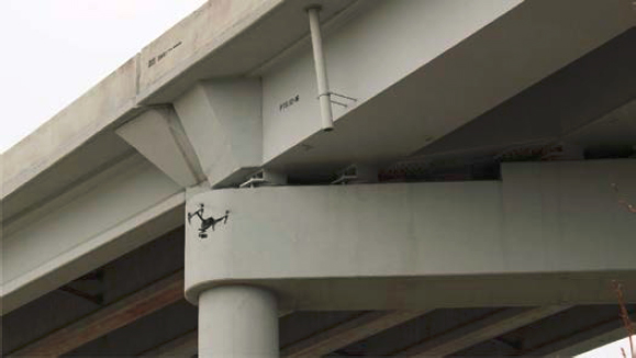
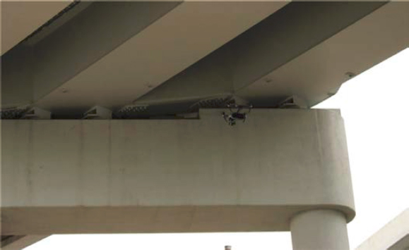
making longitudinal flights with the UAS at a 10–15 ft horizontal offset and above the height of the bottom flange. To inspect the interior girders and deck soffit, the FF2 UAS was flown either from the exterior of the structure or from underneath, depending on the structure and site characteristics. When the bridge was inspected from the exterior, the UAS was flown at an approximate 5-ft vertical offset and 10- to 15-ft horizontal offset, with the camera gimbal tilted upward at about 30°, as shown in Figure 34. In this manner, with the zoom lens, the UAS collected imagery of the deck soffit, one face of the girder web, and the bottom flange of the interior girders. A second flight from the opposite side of the structure was also flown to collect imagery of the other face of the web of the girders. The second method of inspecting the deck soffit and interior girders involved flying longitudinal scans down individual girder bays, with a vertical offset and the camera gimbal tilted upward, as shown in Figure 35. The UAS did not fly between the girders or above the bottom flange because of the larger size of the airframe. The UAS was equipped with obstacle avoidance, though it was not as sensitive as that of the FF1 UAS, which decreased the remote pilot’s comfort, especially when the UAS was flown at farther distances.
Whether the UAS was flown on the exterior or the interior of a bridge, incorporating the sensor operator and dual controls improved the workflow: the remote pilot focused on maintaining control of the airframe while the sensor operator adjusted the exposure and zoom settings to collect high-quality data. An example of the dual operator workflow is shown in Figure 36. While inspecting cables from the outboard side of the structure (as on Bridge 2, Bridge 7, and Bridge 9),
the mechanical zoom lens was capable of detecting deficiencies on the inboard side of cables on the opposite side of the bridge, as shown in Figure 37. This meant a second flight on the inboard side, and the associated traffic control was not needed.
Although the FF2 UAS was flown at farther distances with the zoom lens, the airframe was less capable than the FF1 UAS while inspecting intricate details, such as the cable anchorages on the fascia girder of Bridge 2. Supplemental illumination was used when the FF2 UAS was flown inside a masonry tunnel at the abutment on Bridge 11, but the equipped zoom lens was inadequate because of its smaller aperture. Once the lens was swapped for a prime (fixed focal length) lens with a larger aperture, the FF2 UAS captured sufficient imagery of deficiencies on the masonry and steel elements, even with little to no supplemental illumination, as shown in Figure 38.
Regarding the observed deficiencies at all structures, the FF2 airframe with a higher-resolution camera and prime or zoom lens was able to capture adequate imagery of corrosion, section loss, distortion, and cracking in steel elements. In concrete and masonry elements, the UAS captured imagery of cracking, spalls, delaminations, exposed rebar, corrosion, efflorescence, mortar breakdown, and masonry patches. The airframe also observed cracking, splits, checks, and section loss on timber elements.
When flown in an automated flight pattern at scour-critical bridges, the FF2 airframe collected adequate imagery of the two structures, the channel, and scour effects. These images were combined
to create an orthomosaic of the site, shown in Figure 39. The automatic features simplified the flying and data collection compared with the FF1 airframe, but the two orthomosaics are comparable and could be used to document the channel conditions and scour effects.
3.2 Time Comparison
A Routine Inspection would be more efficient than a UAS-based inspection at structures such as concrete and steel multi-girder systems, where a visual inspection would typically be performed from the ground or bridge deck using binoculars. Using a UAS in these situations would improve the quality of the inspection by providing enhanced access and better viewing angles but may increase time on site. Conversely, a UAS-assisted inspection could improve the efficiency and safety of Routine Inspections typically conducted from a UBIT or an aerial lift. In these cases, using a UAS could reduce or eliminate the need for heavy equipment, maintenance of traffic, or working in traffic.
A brief time comparison for inspections conducted at the selected bridge sites is given in the following sections, but an overview of the time required to inspect common primary elements is warranted. First, substructure elements (piers and abutments) were the most accessible elements for UAS-based inspection, and each face of concrete columns, walls, or caps required 2–5 minutes to scan. Timber substructure elements required an additional 1–2 minutes because of in-flight maneuvering. Second, it took about 5–10 minutes to scan an average 200-ft-long bay of a girder
and floor-beam/cross-frame system, including bearings. This means it would take 30–40 minutes to conduct an inspection of the interior and exterior girders in a span with 5–6 girder lines. Additional bearings or pin and hanger connections would require an extra 5–10 minutes for the 5 or 6 girder lines. Third, vertical cable and hanger elements can be scanned in 2–4 minutes, whereas diagonal elements can be scanned in 3–6 minutes, depending on the length of the cable or hanger. If the inboard face of the opposite cable is also scanned, it would take an additional 3–6 minutes per cable. Finally, planar exterior arch and truss elements (chords, verticals, diagonals, and gusset plates) require 2–5 minutes per element, depending on the system and inspection requirements. For example, inspecting the interior of gusset plates would increase the required inspection time. These times do not include data management or battery changes.
3.2.1 Bridge 1
A Routine Inspection of the two steel multi-girder structures may take 1–2 hours for a team of two inspectors if conducted from the ground or 2–4 hours if conducted from a UBIT. An inspection conducted with UAS may take 1–2 hours because of site constraints and known existing cracking at cross frames.
3.2.2 Bridges 2 and 3
A Routine Inspection of the cables, main span steel floor system, and prestressed concrete multi-girder approach spans may take 4–6 hours for a team of two to four inspectors performing the inspection from the ground and a UBIT. An inspection of the cables with UAS took about 8 minutes to scan both sides of the cables. For reference, an in-depth inspection of the cables took 9 days with six rope-access inspectors, whereas a complete Routine and Fracture-Critical Inspection took 4 days for a team of four, with two inspectors using a UBIT and rope-access techniques and two operating the UAS.
3.2.3 Bridges 4, 5, and 6
From the ground or a UBIT, a Routine Inspection of the steel through truss may take 6–8 hours for a team of two inspectors and 30–60 minutes per span for the prestressed concrete and steel multi-girder approach spans. Conversely, a Routine Inspection of the approach spans with UAS may take 10–30 minutes per span. While inspecting the exterior truss elements, the UAS flew a circuit (across the lower chord, up a vertical, across the upper chord, and down the opposite vertical) in 10 minutes and may inspect the exterior of all truss elements in 4–8 hours. For reference, a complete Routine and Fracture-Critical Inspection of the structure took 3–4 days for a team of nine inspectors using a UBIT, rope-access techniques, and UAS to inspect for global distortion, gusset plates, and substructure elements.
3.2.4 Bridges 7 and 8
A Routine Inspection of the main span deck may take 1–2 hours for a team of two inspectors walking the deck and 15–30 minutes per span to inspect the steel multi-girder approach spans from the ground. A Routine Inspection of the main and approach span floor systems with a UBIT and a team of two inspectors may take 6–8 hours total. An inspection with a UAS took 10–30 minutes per approach span and 4–5 minutes to inspect both sides of the main span cables. For reference, a complete Routine and Fracture-Critical Inspection in 2016 took 8–9 days to inspect the full length of the main span cables with a team of eight rope access inspectors. Two years later, a combined hands-on and UAS-assisted inspection of the structure took 4–5 days with eight rope access inspectors and two UAS operators.
3.2.5 Bridges 9, 10, and 11
A Routine Inspection of the steel truss, open grid deck, and masonry towers may take 2–4 hours for a team of two inspectors walking the main span deck. With a UAS, an inspection of the tail span floor system took approximately 20 minutes, and an inspection of the tail span main cable took 10 minutes per side. For reference, a complete Routine and Fracture-Critical Inspection of the suspension cables, stiffening truss, floor beams, and towers took 4 days for a team of seven inspectors using rope access techniques.
3.2.6 Bridge 12
A Routine Inspection of the steel truss arch would take a team of two inspectors 2–4 hours while walking the main span deck and an additional 2 days to inspect the main span and steel multi-girder approach span floor systems using a UBIT. A Routine Inspection of the approach span floor system took 30 minutes per span when performed with a UAS, while inspecting both sides of each hanger took 4–5 minutes.
3.2.7 Bridges 13 and 14
A Routine Inspection of a typical steel multi-girder span may take 10–15 minutes if conducted from the ground or 30–60 minutes if performed using an aerial lift. Using a UAS, a Routine Inspection may take 15 minutes per span to document and monitor major cracking changes.
3.2.8 Bridges 15 and 16
A Routine Inspection of a typical prestressed concrete or steel multi-box girder approach span may take 30–60 minutes when conducted from an aerial lift or from the ground, or 15 minutes per span if a UAS were flown through each girder bay. Both methods would involve inspecting only the outside of the box girders.
3.2.9 Bridges 17 and 18
A team of two inspectors may complete a Routine Inspection of these structures in 1–3 hours from the ground or bridge deck, depending on the detail required and whether timber sounding or coring was performed. If a UAS were used, a Routine Inspection may take 15–30 minutes per structure to document major deficiencies.
3.2.10 Bridges 19 and 20
A Routine Inspection of these two prestressed and reinforced concrete multi-girder structures may take 10–15 minutes per span when conducted from the ground and deck, or approximately 15 minutes per span if a UAS were used. The automated UAS mapping flights took 30 minutes to document the channel scour conditions.
3.2.11 Bridge 21
A Routine Inspection of the deck truss conducted from the ground or catwalks may take 15–30 minutes per span. An inspection of the exterior truss elements conducted with UAS and a team of two inspectors may take 15 minutes per span, depending on the complexity of flying required. An inspection of the interior truss elements, with the UAS flying vertically between truss lines and rotating in each bay, may take 10 minutes per span. For reference, a Routine and hands-on
Fracture-Critical Inspection of the floor system may take 60–90 minutes per span for a team of two inspectors using a UBIT and rope-access techniques.
3.2.12 Bridge 22
A Routine Inspection of the main span conducted from the deck or lift tower stairs may take 4–8 hours for a team of two inspectors. The truss and cable systems require a hands-on inspection conducted from a lift or by rope access. If inspected with UAS, a Routine Inspection may take 15–30 minutes per tower for a team of two inspectors, including battery and data management. A UAS-assisted inspection of the exterior truss elements may take 10–15 minutes per panel (a circuit of verticals, chords, and diagonals).
3.3 Data Processing and Review
As part of the data processing, select videos from three sites were sent to three inspectors to review. The intent was for inspectors to evaluate UAS-collected imagery from an inspection for which they were not present. The three inspectors had varying levels of experience and were asked to assign condition states to the major elements visible in the videos. In general, all reviewers were able to assign condition states to most visible elements, with two reviewers estimating quantities (linear feet or square feet). The third reviewer estimated percentages for the four condition states. One reviewer noted having to “guesstimate distances,” as distances or member sizes were not shared with the reviewers. The same reviewers also noted a “moderately bent diaphragm angle [that they were] not able to measure” and a concrete crack that they “had to assume . . . was a moderate-width crack” because they were not able to measure the width.
The desktop review test was conducted to confirm the adequacy of the UAS data and the necessity of data review processes in the field. The reviewers noted that the UAS-based desktop inspection limited their ability to view the entirety of some elements. For example, a reviewer noted that they “could not verify that stiffeners were not welded to the bottom flange” when reviewing videos captured by the larger FF2 airframe but did not make that comment regarding the imagery gathered with the FF1 airframe. The researchers identified this same limitation while conducting the inspections and recognized that the larger FF2 airframe could not be used to inspect the top of the bottom flange of interior steel girders, floor beams, or stringers. Neither of the two airframes could access hard to reach areas such as the inside faces of pin and hanger connections. Finally, two reviewers noted areas that would likely require a more in-depth inspection: one being distortion at a steel cross frame that could lead to cracking and the other being a poor-quality vertical butt weld, confirming that reviews in the field need to be conducted to verify data adequacy.
It was apparent from the comments that inspectors could perform an inspection solely using UAS-collected imagery but were limited by their inability to see certain elements or the entirety of elements, measure defects, or immediately follow up with a more in-depth inspection before leaving the site.
As mentioned, a small set of inspection data was sent to two firms, Company 1, with AI trained to identify cracks in concrete, and Company 2, with AI trained for detection of cracks in flexible pavements and some concrete, to evaluate the incorporation of current AI detection into bridge inspections using UAS-collected imagery. The selected data was from the prestressed concrete I-girder approach spans at Bridge 3. Both firms processed the data using their respective algorithms and presented the results in an online interface.
For bridge inspections, Company 1 used their photogrammetry engine to create a 3-D photogrammetric model, which served primarily as a navigational tool to assist the user in identifying
the location and orientation of higher-resolution still images. To reliably create the 3-D model, the UAS must take still images at consistent intervals, from a constant standoff distance, and with sufficient overlap for the entire structure. This typically requires automation and the UAS to fly a preprogrammed route. Generally, the model cannot be reliably created from a video stream because the quality is too low for this application.
Advancements in AI have shown that video can be evaluated in native format. However, as only still images of the prestressed concrete girder approach spans at Bridge 3 were initially shared with Company 1, the AI detection provided variable results. When the AI evaluated additional imagery of the reinforced concrete piers and web walls at one of the scour-critical bridges, which were inspected in more detail with automated mapping flights, the algorithm identified concrete cracking, spalling, and efflorescence. At the time of the research, the AI models incorporated into the program could only identify these common concrete defects. The observed cracking in the reinforced concrete elements was also much larger than the cracking in the prestressed concrete girders, which may have improved the results of the AI-based detection.
Conversely, Company 2 performed an AI analysis using only the 2-D images from Bridge 3 approach spans but acknowledged that their algorithm was trained to identify cracks only in asphalt pavements. Because of this limitation, the crack detection algorithm did not successfully identify the apparent cracks in the images. Members of Company 2’s technical support team were also unable to identify the cracks solely on the basis of their own observations. This demonstrated the importance of training AI detection models for bridge-specific materials and deficiencies. Equally important are that the individuals training the models understand structural engineering and common defects and have experience conducting bridge inspections. Company 2 noted that their models can be trained for specific applications and materials, so with more precise training, results would likely have improved.
Although commercial AI detection services are available, the current options are limited by the maturity of the technology and the training data set. AI-based inspection technology is still relatively young, and only recently has there been focused effort to apply the technology to bridge inspections with element-level data collection. Furthermore, most research has focused on detecting cracks and other deficiencies in concrete and asphalt materials in which defects are readily detectable. Some research has been conducted on detecting cracks in steel materials, but there is a need to accurately train models with data sets that encompass a wide range of structural materials, systems, details, and condition states. This is a time-consuming and labor-intensive process that must be done by qualified personnel, but it is necessary to capture the breadth of conditions encountered in bridge inspections across the country.
AI applications hold promise for bridge inspections, but bridge owners need to treat the technology as another tool to assist inspectors in identifying a limited subset of elements and condition states present in a Routine Inspection with element-level data collection. Commercially available services also provide non-AI benefits, including georeferenced images, 3-D models, point clouds, measurement tools, and historical comparisons.


