On-Street Bicycle Facility Design Features: A Guide (2025)
Chapter: 4 Design Factors Impacting Bikeway Safety
CHAPTER 4
Design Factors Impacting Bikeway Safety
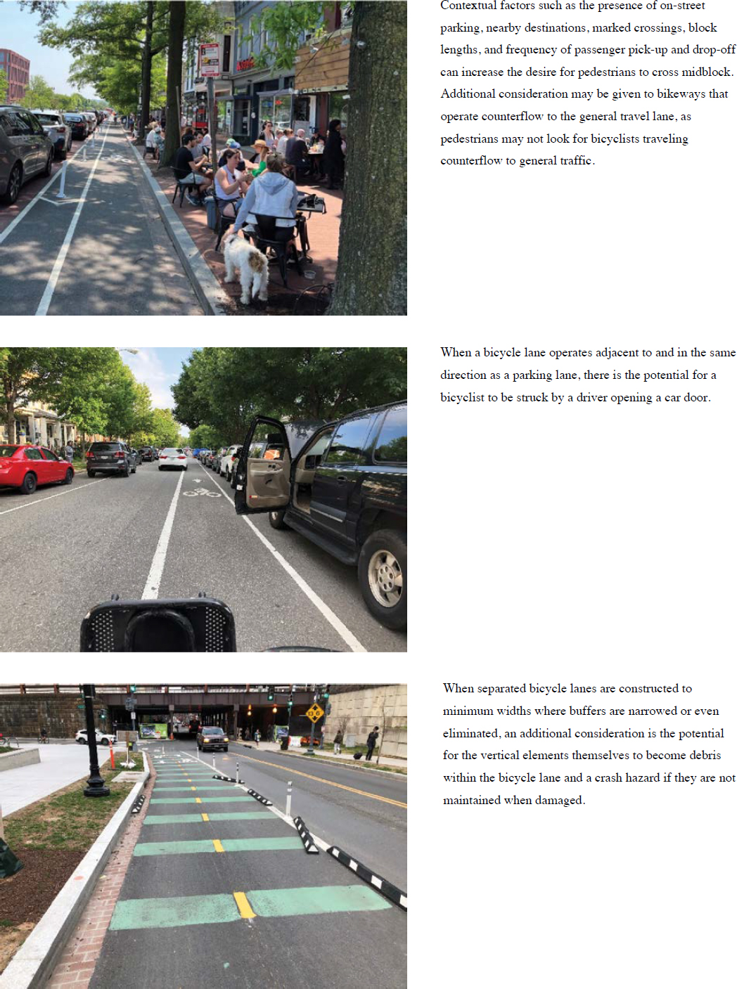
While the safety data analysis conducted for this study showed that all bikeways improve safety outcomes for bicyclists, the visual assessment of separated bicycle lane crash sites revealed factors outside of the available data that have been suspected to impact bicyclists’ safety which designers need to be aware of. Many of these factors can be mitigated by discrete design choices. In some instances, there may be a need to consider trade-offs between design and operational elements at locations where more conflicts are expected (e.g., driveways, parking garages, parking lots, and alleys with midblock access points).
The following provides a general discussion of key design elements that can improve the safety and comfort of bicyclists operating midblock on a bikeway. These design elements are considered critical based on the existing state of the practice research and guidance. They are further informed by the visual assessment of crash locations conducted as part of this study. In this chapter, the research team summarizes relevant guidance for each element where it is available and provides an analysis of the relationship of that guidance to the design of bikeways at separated bicycle lane crash locations. The research team notes where the guidance as written may have been beneficial to address the issues at the crash sites observed. Suggestions to supplement existing guidance are offered to address issues found at these sites, with recommendations for further detailed research as applicable.
While a primary focus of the provision of bikeways is to reduce fatalities and serious injuries primarily resulting from crashes with motorists, it could also be a goal of agencies to reduce injuries to bicyclists where the condition of a bikeway can be a contributing factor. Research of hospital records estimates that 50 to 70 percent of all bicyclist-only crashes typically result in less severe injuries and may not be reported in agency or national crash databases (Schepers et al. 2017). Research indicates that many of these crashes may result from infrastructure issues, including a lack of maintenance (Schepers et al. 2017). Therefore, this guidance also discusses critical maintenance needs that could be considered during planning and preliminary design and provides a discussion of maintenance policies and practices that could be adopted by agencies seeking to provide networks of safe, comfortable, and attractive bikeways for all ages and abilities.
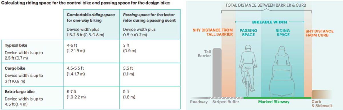
4.1 Bikeway Width
Bicyclists require an operating space of 48 to 60 inches to accommodate a single lane of travel; therefore, design guidance typically recommends a minimum bicycle lane width of 4 to 6 ft for a range of bicycle types. This minimum operating space allows for the natural side-to-side motion that occurs while people bicycle. The minimum operating widths do not account for the provision of additional shy distance to most other vertical elements (e.g., utility poles, on-street parking,
or guardrails) that may be adjacent to a bikeway, nor do they account for the reaction space necessary for bicyclists to avoid collisions with objects or people that may suddenly enter the bikeway. Guidance for shy distance to vertical elements varies between sources, with most recommending wider bicycle lanes to improve the comfort and safety of bicyclists operating near vertical elements. The provision of an extra 12 to 36 inches of space is the typical range suggested.
Accommodating Other Users of Bikeways
While performance characteristics for micromobility devices are limited and not incorporated into this guidance, providing bikeway designs which accommodate adult bicyclists and the “interested but concerned” design user will generally lead to the establishment of geometric and operational design criteria that will result in bikeways that accommodate all users, including people using micromobility devices and personal assistive mobility devices.
A wider bicycle lane width can provide a more comfortable environment for people riding bikes, allow bicyclists to operate side-by-side (social bicycling), create space for a bicyclist to pass other bicyclists, and provide space to navigate around objects or people who may suddenly appear within their operating space. The literature review identified a study (Park and Abdel-Aty 2021) that found a 5 to 6 ft bicycle lane width had positive implications for reducing vehicle crashes, while 6 to 7 ft bicycle lane widths were effective in reducing nonmotorized vehicle crashes (bicyclist and pedestrian). Wider bicycle lanes may also be beneficial to support micromobility devices, which are required by law to operate within bikeways in many communities. NACTO published revised bikeway guidance to consider wider bicycles and wider operating spaces to accommodate passing and social bicycling (Figure 8).
Where vertical elements are installed to create separated bikeways, bikeway width between the vertical elements will be a key consideration for maintenance access. When designing the bikeway, the ability of the maintenance team to access and maintain the bikeway needs to be a key consideration. At locations where the bikeway operating space is less than 8 ft, new equipment or changes in maintenance practices may be required (Section 5.5).
When retrofitting existing roadways, it may be necessary to evaluate multiple bicycle facility types based on the available right-of-way space when minimum-width bikeways are under consideration. A suitable bikeway width could be selected to accommodate planned bicyclist volumes and actions such as bicyclists operating side-by-side or passing one another, as appropriate. Additional information to help practitioners make informed trade-off decisions related to the selection of bikeway types that support connected, safe, and comfortable bicycle networks that meet the needs of people of all ages and abilities can be found in the FHWA Bikeway Selection Guide and the AASHTO Bicycle Guide (2023).
Narrower-than-recommended separated bicycle lanes or buffers next to a vertical curb or parking result in less space for bicyclists to react to and avoid obstacles such as pedestrians crossing the bikeway, the opening of car doors, and debris in the bicycle lane (Figure 9). They may increase crash risks for bicyclists during passing events or when operating side-by-side; however, this potential increase in crash risk has not been studied. Wider bikeways and buffers allow bicyclists to avoid these conflicts, to safely navigate around obstructions or obstacles, and to pass or operate beside other bicyclists.
4.2 Buffer Design
The provision of a buffer can increase the lateral separation between bicyclists and motorists or provide additional separation to vertical elements or parking. A buffer adjacent to a bikeway can provide a more comfortable environment for people riding bikes, create space for bicyclists to pass or operate beside other bicyclists, or create space to navigate around objects or people who may suddenly appear within their operating space. The FHWA Separated Bicycle Lane Guide recommends a minimum width of 5 ft for separated bicycle lanes and a minimum buffer width of 3 ft when the parking lane is located between the bicycle lane and the general travel lane.
A 3-ft buffer will accommodate the space most vehicle doors will open into; however, additional buffer space adjacent to a parking lane can create space for people loading or unloading from vehicles.
4.2.1 Pavement Marking Design for Buffers
The 2009 edition of the Manual on Uniform Traffic Control Devices (MUTCD) did not provide standards or guidance for the use of pavement markings in the buffer of a buffered bicycle lane or separated bicycle lane, which led to the emergence of multiple strategies and localized standards. Since there is limited research into the specific styles and dimensions of markings that relate to legibility and safety performance, agencies typically choose marking strategies that fit within their operations and maintenance capabilities as well as bikeway visibility goals.
For many agencies, a primary consideration in the design of a pavement buffer is the quantity of pavement markings because it increases short-term installation costs and potentially long-term maintenance needs. These added maintenance costs may impact design decisions related to the spacing of lane lines as well as their width and thickness. A secondary consideration is how the pattern markings are applied and whether the strategy requires more workers, specialized equipment, or time to install. Using materials that have the longest lifespan while achieving the desired retroreflectivity and visibility performance characteristics over materials that may be cheaper to install but require frequent refreshing could be considered. There is no current research that demonstrates a particular marking strategy is most effective; therefore, maintenance considerations need to be a primary consideration when developing a buffer design.
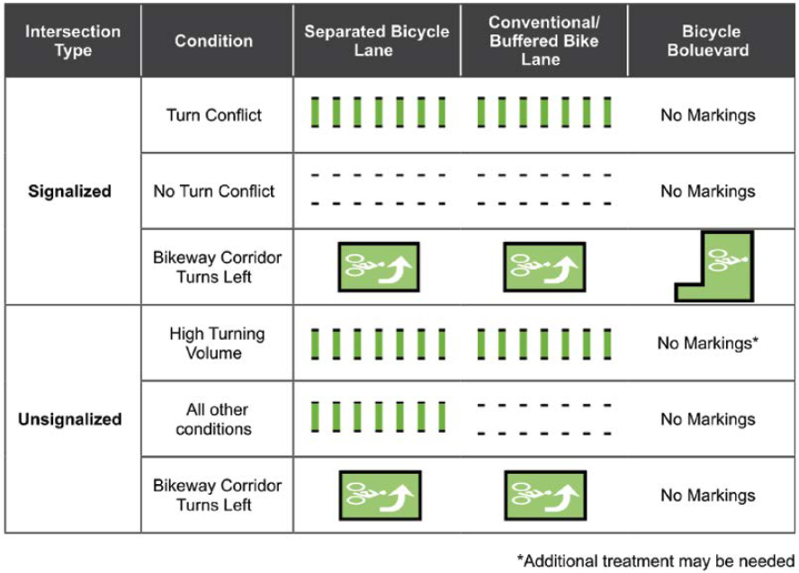
The AASHTO Bicycle Guide recommends the patterns as shown in Figure 10, which is similar to MUTCD guidance.
4.2.2 Lateral Placement and Spacing of Vertical Elements
Currently, there is no national guidance on where to place vertical elements within a bicycle lane buffer. The type of vertical element used and longitudinal spacing and lateral location in a separated

bicycle lane buffer can impact the effective bikeway width and bicyclist comfort and safety. Vertical elements can impact where motorists park within a parking area. Some motorists may park as far away from an active travel lane as possible to allow more egress and ingress room for drivers (see Figure 11), which can lead to encroachment into a bicycle travel lane and reduce the benefit of buffer space intended for loading or opening vehicle doors. This potential encroachment into a bicycle lane can become more frequent when constrained travel lanes and parking lanes are selected by the designer or are a necessary outcome to provide a separated bicycle lane in constrained corridors.
In locations that are not constrained, designers have some flexibility in the placement of vertical elements. Some designers choose to place vertical elements within the buffer as close as possible to the bicycle lane to minimize vehicle strikes to the vertical elements or to create additional space for vehicle doors to open without striking a vertical element. For some agencies, this choice results from a desire to limit maintenance of the vertical element. However, a consequence of this design choice is that motorists can encroach further into the bicycle lane buffer than intended by the designer, thereby reducing the effective bikeway width, which can increase crash risks for bicyclists or decrease their comfort in the bikeway. It is also not guaranteed that this placement will


minimize maintenance needs, as motorists may still damage the vertical elements when parking or loading. The type of vertical element and spacing needs to be carefully considered concerning factors such as motorist speed and volume, the presence of transit, the presence of an adjacent parking lane to the bikeway, local destinations, parking and loading demand, and maintenance needs of the bikeway with an understanding of the potential impacts to users of the bikeway.
An additional maintenance consideration for agencies is the use of temporary versus permanent materials. Temporary vertical elements have allowed agencies to rapidly retrofit streets to implement separated bikeway networks; however, in some cases, this has required an increase in maintenance needs to replace and repair damaged vertical elements. As these bikeways are upgraded to permanent installations, agencies are increasingly using a variety of more durable vertical elements, such as dowels in concrete barriers, modular concrete barriers, extruded or precast curbing, small medians with curbing, or they are fully raising these bikeways to sidewalk level during street reconstructions. These projects create opportunities to minimize ongoing maintenance needs associated with temporary materials; however, the primary issue of ensuring the bikeway is free of obstructions remains a critical design and policy decision, especially as it relates to the provided clear width between the vertical elements (Section 5.5).
4.3 Sight Distance
The provision of appropriate sight distances is essential to allow street users to see each other, have time to make decisions, and respond accordingly to avoid a crash. For midblock locations, the necessary sight distances fall into three main categories:
- Sight distances for drivers and bicyclists traveling on the street.
- Sight distances for drivers and bicyclists when the motorist is turning across the bikeway to access a driveway or alley.
- Sight distances for drivers entering the street (crossing the bikeway) from a driveway or alley.
Sight distance guidance for drivers and bicyclists traveling on the street will differ based on the type of bicycle facility and the site conditions. This includes sight lines for bicyclists and motorists outlined in the AASHTO Green Book, which could be provided to ensure street users can see each other when the bicyclist is traveling within a conventional bicycle lane, buffered bicycle lane, or shared lane to avoid rear-end or overtaking crashes by motorists striking bicyclists. For these bicycling conditions, the roadway geometry design for motor vehicles will often result in
sufficient sight distances when bicyclists are operating at speeds below the roadway design speed. Designers may consider the speed and location of the bicyclist in a buffered bicycle lane and confirm that these sight lines are adequate. When bicyclists operate in separated bicycle lanes, rear-end and bicyclist-overtaking crashes are not possible unless the motorists enter the separated bicycle lane or the separated bicycle lane transitions to a shared lane or conventional bicycle lane.
Sight distances for drivers turning into a driveway or alley are similar to intersection sight distances. For conventional and buffered bicycle lanes, motorists are expected to merge into the bicycle lane approaching the driveway or alley after they have confirmed there are no bicycle conflicts. This requires the same geometric roadway sight lines from the AASHTO Green Book. However, while the provision of these sight lines is generally accommodated as part of common roadway designs, these conventional bicycle lanes and shared lanes are overrepresented in rear-end and bicyclist-overtaking crashes, as well as right-hook crashes, which occur when motorists do not merge into the bicycle lane but instead overtake the bicyclist and turn in front of them at a higher speed (Pai 2011). Conflicts that occur when drivers merge into a conventional bicycle lane or turn across their path at a driveway or alley can happen before the motorist has slowed to navigate the turn, resulting in potentially higher-speed crashes. For separated bicycle lanes, motorists cannot merge into the bicycle lane approaching the driveway or alley and must turn across the bicycle lane at the access point, which can result in lower-speed conflicts compared to conventional bicycle lanes and shared lanes at conflict points. Transitioning conventional or buffered bicycle lanes to separated bicycle lanes at higher-volume driveways and alleys may help mitigate crash risk at locations where conflicts are caused by improper motorist merging or higher motorist turning speeds.
The AASHTO Bike Guide (2023) provides new methods to evaluate sight distances for separated bicycle lane conditions. These sight distances are based on stopping sight distances, motorist turning speeds, and typical bicycle operating characteristics. As shown in Figure 12 and
Table 2. Suggested approach clear space (AASHTO 2023).
| Effective Vehicle Turning Radius | Vehicular Turning Speed | Recommended Approach Clear Space |
|---|---|---|
| < 18 ft | <10 mph* | 20 ft |
| 18 ft | 10 mph | 40 ft |
| 25 ft | 15 mph | 50 ft |
| 30 ft | 20 mph | 60 ft |
| >30 ft | 25 mph | 70 ft |
* Most low-volume driveways and alleys.
Table 2, when on-street parking or other potential sight-line obstructions occur within the street buffer between a separated bicycle lane and adjacent travel lane, those obstructions need to be eliminated to provide sufficient sight lines and time for a motorist or bicyclist to see the other user and have time to slow or stop before reaching the conflict point. This concept of approach clear space is based on the characteristics of the motorist’s movement (e.g., how fast or slow they will turn) and recognizes that motorist turning speed is influenced by the effective turning radius for that turning movement (Fitzpatrick 2004, 2022). Most low-volume driveways and alleys are likely to have a small effective turning radius that requires drivers to turn more slowly, where a 20-ft approach clear space would be appropriate. However, some low-volume driveways or alleys that are used for commercial purposes (e.g., deliveries, large trucks) may have larger effective turning radii, and the potential for higher vehicular turning speeds needs to be considered. Where higher bicyclist speeds are likely to occur (such as when traveling downhill), these sight distances may be increased to account for the longer stopping sight distances for the bicyclist.
For left-turning motorists across a one-way separated bicycle lane, the provision of the approach clear space for the right-turning motorist will generally accommodate sight distances between the motorist and bicyclist traveling in the opposite direction. For left-turning motorists across a two-way separated bicycle lane, the left-turning motorist needs a sight line to bicyclists approaching from the same direction, as shown in Figure 13. The same approach clear space distances shown in Table 2 still apply, but the effective turning radius is typically larger than the right turn and requires a longer approach clear space. On streets with two-way traffic flow, the operational dynamic of a motorist looking for gaps in traffic creates unique challenges that cannot be resolved through improving sight distance. This maneuver increases motorist workload because the motorist is primarily looking for gaps in oncoming motor vehicle traffic, and they are less likely to scan for bicyclists approaching from behind. Further increasing crash risk, the motorist often accelerates toward the crossing once they perceive a gap in traffic, which increases the risk of injury to bicyclists and other users in the crossing area. Prohibiting these left-turn movements and eliminating the bicycle-motorist conflict are suggested if traffic volumes or operating speeds are high, multiple conflicting motorist lanes are present, or existing left-turn volumes are high.
Sight distances for drivers exiting a driveway or alley are impacted by potential sight obstructions behind the curbline (e.g., large trees, tall street furniture, walls, building facades) and sight obstructions created by on-street parking. Both types of sight obstructions relate to conventional bicycle lanes, buffered bicycle lanes, and shared lanes, but only the sight obstructions behind the curbline relate to separated bicycle lanes. However, on-street parking can limit sight lines between motorists exiting the driveway and those operating in the travel lane, which still needs to be considered for driveway operations. Bicyclists and motorists operating in the street have the right-of-way over motorists exiting driveways and alleys. While gap acceptance is used to establish typical sight lines for motorists looking for gaps in motorist traffic to exit stop-controlled

locations, motorists often have more difficulty assessing bicyclist speeds and looking for gaps in bicyclist traffic. At a minimum, bicyclist stopping sight distances could be provided to allow time for bicyclists traveling from the left and/or right to slow or stop if a vehicle encroaches into their path (Figure 14). Although uncommon, if driveways or alleys are expected to facilitate motorists through movements (e.g., to continue along an alley or go from one driveway to another), then sight distances to bike facilities on the opposite side of the street could be considered (Figure 15). Like the previous example, at a minimum, stopping sight distances for the bicyclist to see and slow for motorists need to be provided.
4.3.1 On-Street Parking Restrictions
On-street parking can represent a sight-distance obstruction along all types of bicycle facilities. On-street parking can affect sight lines between drivers exiting driveways or alleys and impact their ability to see bicyclists within conventional bicycle lanes, buffered bicycle lanes, and


shared lanes. For separated bicycle lanes, on-street parking can affect sight lines between drivers entering driveways or alleys and impact their ability to see bicyclists.
Where on-street parking is permitted, many agencies have existing guidance or regulations restricting on-street parking near driveways or intersections; however, these policies are not always followed during design to maximize on-street parking availability. In other instances where parking is not physically prevented, motorists may illegally stop or park in no-parking areas identified by signs and/or markings. Furthermore, the existing guidance or regulations restricting parking near driveways or alleys (i.e., 5 ft, 10 ft, or 20 ft from the edge of the driveway) may not accommodate the sight distances discussed in the previous section. For corridors with commercial driveways spaced 100 ft apart or less, designers could consider eliminating on-street parking between these driveways in favor of maximizing sight distances (AASHTO 2023).
Designers must consider the technical and political realities associated with on-street parking restriction or removal and assess the safety risks of not restricting on-street parking to meet recommended sight lines and clear zones during conceptual planning and design. For example, restricting on-street parking near low-volume residential driveways is often politically challenging where people are accustomed to having an abundance of parking available near their residence. Crash data shows that crashes rarely occur at these locations in part because driveway use can be very infrequent during a typical day; therefore, the relative risk of a collision is low even at locations where the recommended clear space is not provided. By comparison, restricting on-street parking near high-volume parking garage driveways may also be challenging, but these locations show a greater risk of crashes where on-street parking is a factor in restricting sight distance between street users.
Parking restriction or removal along streets where parking demand is high will still often need reasonable accommodations for parking and loading to occur, as failure to provide those accommodations may increase the likelihood that vehicles will park or load from within the bikeway. Where on-street parking restrictions are being considered, designers may recognize that different strategies for restricting on-street parking have a wide range of effectiveness and corresponding safety outcomes. Some of these strategies are discussed below:
- Signs and pavement markings—The use of no parking (R7-1), no standing (R7-4), and no stopping signs are a common strategy used to indicate where motor vehicles are restricted. Rules governing the use of these signs differ by local ordinances, but in general the most restrictive (i.e., prohibiting any stopping at all) is preferable as vehicles stopping in these areas will restrict sight lines for motorists and bicyclists at driveways and alleys. If stopping is not prohibited, designers need to recognize that drivers will stop their vehicles in these spaces for deliveries and other short-term operations or to illegally park. Where short-term curbside operations are desired on a street, these spaces could be designated in lieu of on-street parking spaces in areas outside of the desired sight triangles or approach clear spaces. Locating these short-term operating spaces near driveways or alleys may have the added benefit of providing additional sight lines when vehicles are not using these spaces. Areas with parking restrictions may be supplemented with pavement markings with a no parking “X” or diagonal crosshatch marking style being typical (e.g., gore markings). The use of signing and pavement markings is the least physically restrictive of the noted treatments which can accommodate faster-turning vehicles using these spaces to turn into or out of driveways and alleys.
- Physical objects—The use of physical objects, such as flexible delineator posts, precast curbs, or other tactical treatments can supplement signing and pavement markings to physically deter motorists from using street areas to park, stand, or stop, thus helping to preserve sight triangles near driveways or alleys. These treatments also have the benefit of physically controlling effective turning radius and turning speeds for vehicles turning into or out of driveways and alleys.
- Curb extension—Curb extensions may be used on capital improvement projects to reconstruct curb lines to prohibit on-street parking near driveways and alleys. These treatments also have the benefit of defining the effective turning radius and turning speeds of vehicles. Curb extensions have the benefit of being able to accommodate midblock crosswalk locations for pedestrians where those crossings are desired by shorting crossing distances and allowing pedestrians to begin their crossing closer to the edge of travel lanes where they are more visible. Curb extensions can also be designed to provide protected intersection geometry, allowing conventional bicycle lanes or buffered bicycle lanes to be transitioned to separated bicycle lanes at driveways and alleys.
- Mountable truck aprons—The use of truck aprons could be used at alleys and higher-volume driveways where accommodating the off-tracking of larger vehicles is desired. These treatments can help to physically restrict on-street parking or stopping and help to reduce turning speeds for passenger vehicles while still being functional spaces for other street uses (e.g., emergency services use). Mountable truck aprons can also supplement curb extensions as part of a protected intersection design at a driveway or alley.
4.4 Traffic Control at Driveway and Alley Crossings
Bikeway crossings at driveways and alleys need to be easy to recognize and intuitive to use. Applying Safe System intersection design principles, bicyclists, pedestrians, and motorists approaching a driveway or alley need consistent cues that both raise awareness of the conflict point and clearly reflect which users have the right-of-way. Even without any traffic control devices, state codes generally require motorists to come to a complete stop before exiting a driveway or alley and to yield to pedestrians when making left or right turns across a driveway. The specific language varies across jurisdictions, but the right-of-way priority given to crossing pedestrians is generally consistent. State codes are sometimes less clear with respect to expected behavior at driveways when there is a bikeway present, but many state codes extend the rights of pedestrians to bicyclists; regardless, all state codes require motorists to exercise due care when turning and to yield to conflicting users within a crossing.
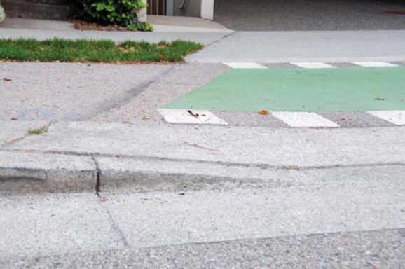
It is important that driveway and alley geometry, signage, and pavement markings work together to provide the legibility necessary to ensure user awareness and the mutual understanding of right-of-way priority. An improper application of traffic control can result in significant non-compliance by users resulting in confusion and increased crash risk. Driveway and alley geometry and material choices can also signal right-of-way priority for motorists or crossing pedestrians and bicyclists. Figure 16 is an example where the geometric design and traffic controls at a driveway are applied incorrectly to indicate priority to crossing motorists who do not have right-of-way priority to enter the adjacent roadway or have right-of-way priority over crossing pedestrians for whom the stop control does not apply.
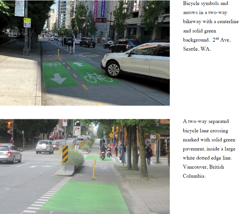
Some jurisdictions are applying traffic control strategies with a nuanced approach based on the driveway context, with more traffic control devices being installed at higher volume driveways and few to none applied at low-volume locations. Other jurisdictions are using a systematic approach to establish a baseline minimum treatment for conflict zones, such as marking all conflict zones with green pavement markings and dotted edge lines, like in Seattle, WA. A sample of the wide variety of approaches observed in this research study can be seen in Figure 17.
4.4.1 Pavement Markings for Driveway and Alley Crossings
Pavement markings can be helpful tools for raising awareness and communicating right-of-way priority; particularly at locations where raised crossings are not provided or practicable.


Across North America, there has been a wide range of approaches to pavement marking strategies at driveways and alleys when a bikeway is present, and this was evident at the study sites. Some common elements include:
- Bicycle-related pavement marking symbols, such as bicycle symbols (sometimes accompanied with an arrow or with bicycle symbols turned to face motorists), chevrons, or shared lane markings (which do not conform to MUTCD practices) to warn motorists of the potential conflict.
- Crosswalk markings, green-colored pavement, or dotted white edge lines to define the crossing.
- Supplemental yield lines to define the driveway location and yield points.
- Longitudinal lines and gore zones to define the driveway approach area.
- Centerlines provided on two-way facilities with bicycle symbols to advise motorists of two-way operation.
- Solid or dashed green paint is becoming increasingly common, particularly on separated bicycle lanes.
- Pavement markings provided to encourage slower bicyclist approach speeds at the conflict point:
- SLOW word messages on the bikeway approach to the crossing.
- Transverse painted bars to act as a “rumble strip.”
At locations where these bikeways cross driveways or alleys, there is no industry consensus for how to mark the bikeway; the buffer lines may remain solid or dotted through the conflict area, and supplemental, green-colored pavement markings, bicycle lane symbols, or other markings such as chevrons may be used to increase the conspicuity of the conflict area. Most agencies develop a standard strategy or policy for these design details within their community and ensure that they are maintained (Section 5.5). Examples of these strategies are shown in Figures 18 and 19.
4.4.2 Traffic Signs for Driveway and Alley Crossings
Traffic control signs can be helpful tools for raising awareness and communicating right-of-way priority, particularly at locations where it is determined that stop control or yield control is necessary. Where restrictive control is desired, it is suggested to follow existing MUTCD guidance. In most instances, this will likely result in restrictive control being placed on motorists exiting driveways or alleys to stop or yield to crossing bicyclists and pedestrians.
At uncontrolled locations, or where there is a desire to add supplemental warning signs, the existing guidance for the selection and application of these signs is often vague or not fully developed. As a result, many communities have been deploying a wide range of treatments to facilitate warning of motorists and/or crossing pedestrians and bicyclists at conflict points associated with driveways and alleys. Some of these signs are not explicitly stated for use in these applications in the MUTCD (e.g., for W11-1 and all word message signs) while the other signs shown are noncompliant with the MUTCD and would require experimental approval by the FHWA for use.

4.5 Driveway Design Considerations
Research to date does not indicate design strategies that are most effective at raising awareness, ensuring compliance, or improving safety outcomes of bicyclists at driveways, except for raised or offset crossings (protected intersections), which have been found to reduce crashes by up to 50 percent (Madsen et al. 2022; Schepers 2017). At a minimum, design guides typically recommend the following strategies be considered to communicate priority right-of-way assignment for crossing pedestrians and bicyclists:
- Provide a raised crossing to create a continuous surface through the driveway with grade breaks to require slower motorist crossings. Raised crossings also provide safety and right-of-way clarity benefits to pedestrians walking on adjacent sidewalks, improve accessibility, and simplify the driveway design.
- Provide consistent material choices or colored pavement to make identification of the bikeway and sidewalk appear to continue through the driveway and not end at the driveway.
- Apply a consistent approach to the use of pavement markings to identify driveway locations and bikeway conflict areas.
- Provide appropriate assignment of restrictive traffic controls following MUTCD guidance where an uncontrolled crossing is not desirable.
The Michigan DOT Sidepath Intersection and Crossing Treatment Guide (2018) provides examples of traffic control applications based on driveway usage, including three tiers of design options. This can be a model for agencies to consider when developing their own contextual guidance for driveway design based on risk to develop a consistent approach to driveway design and operation in their communities. An example of such information applying the driveway volume guidance (Section 3.2) is presented in Table 3.
4.5.1 Driveway Geometry
There is limited national guidance and research on the geometric design of driveways, with the AASHTO Green Book (2018) citing ITE reports from 1974 and 1986 and NCHRP Report 659: Guide for the Geometric Design of Driveways (Gattis et al. 2010a). Through many editions of the Green Book, there has been a recognition that driveways impact the safety and convenience of road users on thoroughfares by introducing conflict points. NCHRP Report 659 (Gattis et al. 2010a) states that “good driveway design should facilitate smooth vehicle egress and ingress to and from the roadway and should also provide for pedestrians and bicyclists.” However, design considerations for bicyclists in the report are limited to providing sight distance between users as provided in the latest AASHTO Green Book, minimizing abrupt changes in cross slope or longitudinal slope for bicyclists, and minimizing the number of grate openings that a bicycle tire may drop into. The report lists objectives for driveway design, including minimizing the width of the driveway that bicyclists and pedestrians will need to cross, but also designing a driveway shape that conforms to the path of the turning vehicle and minimizes encroachment into other lanes (Figure 20). Since the report was published in 2010, practitioners have learned that these
Table 3. Driveway design strategies and countermeasures by number of driveway conflicts.
| Design Strategy and Corresponding Countermeasure | Number of Conflicts at Driveways | ||
|---|---|---|---|
| Minimal | Lower | Higher | |
| < 25 / day | 25-500 / day | > 500 / day | |
| <10 at peak hour | 10-50 at peak hour | >50 at peak hour | |
| Minimize Exposure to Conflicts | |||
Access management (Section 3.4) | |||
Horizontal geometry - Reduce driveway opening (Section 4.5.1.1) | |||
| Manage Motorist Speed | |||
Horizontal geometry - Reduce curb radii (Section 4.5.1.1) | |||
Vertical geometry – Raise bikeway or provide vertical deflection (Section 4.5.1.2) | |||
| Ensure Awareness | |||
Motorist stop/yield signs | |||
Warning signs | |||
Pavement markings (Section 4.4.1) | |||
Dashed lane line extensions | |||
Directional markings (Two-way or contraflow lanes) | |||
Supplemental green pavement markings | |||
Note: See the key below for an explanation of what each shade of gray represents.
| Key | |
|---|---|
| Degree of Countermeasure Necessity | Color |
| Candidate for countermeasure treatment | |
| Countermeasure should always be considered, but not mandated or required, based upon engineering judgement | |
| Countermeasure should always occur | |
objectives are at odds and that facilitating smooth vehicle egress and ingress increases motorists’ turning speeds and reduces the safety of bicyclists and pedestrians traveling along the roadway, either on the sidewalk, a side path, or a conventional or separated bikeway.
Geometric design elements at driveways significantly impact minimizing bicyclists’ exposure to conflict and managing motorist turning speed. Motor vehicle (turning) speeds will be the dominant factor in determining risks for bicyclists and pedestrians at driveway crossings. It is important that motor vehicle design speed criteria at driveways always be as low as possible, preferably at or below 5 to 8 mph. The following geometric features can help to achieve this.

4.5.1.1 Horizontal Geometry
It is important for designers to consider the appropriate design vehicle as well as existing driveway volumes when designing driveways across raised bicycle lanes or retrofitting them for the provision of an on-street bicycle lane. For example, higher volume driveways serving midsize or larger parking structures are rarely able to accommodate a design vehicle larger than a passenger vehicle due to clearance or weight restrictions. If a driveway does not meet the volume thresholds necessary to warrant a traffic signal, then design flexibility at unsignalized intersections with respect to encroachment of vehicles into opposing travel lanes on minor streets could be afforded.
Considering that very low design speed is somewhat unique to driveways compared to intersections, designing driveway access that allows the control or design vehicle access or egress to use the full width of the driveway throat to complete a turn could be considered in most locations. Similar principles might apply when retrofitting a corridor with a separated bicycle lane at roadway grade, making the longitudinal gap in the bicycle lane buffer and vertical protection no longer than necessary to accommodate design and control vehicles, thus minimizing exposure to risk for people bicycling. In locations where it is necessary to accommodate a larger control vehicle, truck aprons may be considered to minimize the driveway width for other vehicles and to control turning speeds.
4.5.1.2 Vertical Geometry
In a typical cross section with positive drainage, the driveway profile grade within the apron is a key feature to help ensure low incoming motor vehicle speeds at driveway conflict points. The approximate sag grade break—the angle where the driveway apron meets the edge of the adjacent travel lane—is the main characteristic commonly used to describe the degree of vertical deflection at driveways.
The various components of a driveway and how they intersect with the surrounding streetscape can result in complex grades that are rarely constant across the width of a driveway and can be challenging to assess. Unlike well-established tools in the transportation industry for analyzing horizontal swept paths in CAD software, there is limited data on typical vehicle ground clearance profiles and limited software that can model the complex dynamic response of a turning vehicle to changes in grades through the various stages of accessing a driveway.
The transportation industry tends to design for outlier vehicles to produce a “conservative” design that will work for all vehicles. At driveway grade breaks, there are often concerns raised that vehicles designed with low ground clearance may strike raised pavement or even end up stuck, such as a car with clearances as low as 3 to 5 inches in and around the front wheels (see Figure 21). This has the effect of limiting grade breaks to conservative values based on a simplistic assessment of typical grade scenarios and a straight-line diagram created from a finite number of points of a
vehicle undercarriage. The ground clearance profile can vary considerably through the length of a vehicle, which can have a significant impact on a vehicle’s ability to clear changes in grading with the front and rear overhang often being the determining factor rather than ground clearance across a vehicle’s wheelbase. Similarly, turning simulation software can result in overly conservative estimates of a design vehicle’s turning path.
The AASHTO Green Book (2018) suggests that a sag grade break not exceed 9 percent, which is also suggested as an upper limit in NCHRP Report 659: Guide for the Geometric Design of Driveways (Gattis et al. 2010a) based on the implication that there should be no likelihood of vehicles striking the pavement. However, the limited “non-fringe suburban” cases examined in that study may not be appropriate to generalize from, particularly for urban settings, due to the small sample size, high posted speeds in the corridors, and large curb returns with long continuous driveway aprons that may all be contributing to those observations. More broadly, some portion of vehicles contacting the road surface may be desirable provided it is not severe or the result of a driver traveling too fast. In situations where it may be a sign of a grade break that is difficult for drivers to see, that is an issue that could be resolved through design.
Within a Safe System context, it may not be practicable to continue to design for vehicles with unnecessarily low ground clearance if it comes at the expense of achieving system safety goals. To improve the safety performance of driveways, it is necessary to reflect carefully on design vehicle needs and consider maximum sag grade breaks beyond current practice; this includes introducing minimum sag grade breaks or limiting the typical length of a driveway apron in the interest of managing motor vehicle speeds at driveways as a design goal with standard driveway details and design guidance to be applied at locations which have a history of safety challenges or can reasonably be expected to generate conflicts such as parking structures which cross pedestrian paths and bikeways.
Based on a sample of suburban locations, the authors of NCHRP Report 659 (Gattis et al. 2010a) concluded that driveways with sag grade breaks between 13.5 and 19 percent were generally steeper than those below 6.5 percent, which were considered “flatter.” Designers may choose steeper sag breaks than the above 9 percent recommended by the AASHTO Green Book (2018) or closer to this range to reduce motorist turning speed. Some existing driveways with raised separated bicycle lanes in urban settings have sag grade breaks that exceed the AASHTO Green Book (2018) guidance, as shown in Figure 22.
Vertical Deflection at On-Street Bikeways
It is common for separated bicycle lanes to be installed at roadway grade, particularly in quick build, retrofit, or interim separated bicycle lane projects that must work within a limited budget or schedule constraints that do not allow significant curb alignment changes. Some jurisdictions have taken novel approaches to still achieving some vertical deflection at driveways in these conditions where safety concerns have presented themselves.
It is an increasingly common practice to provide speed bumps at parking garage driveway exits in the interest of pedestrian safety where the garage design limits motorist sight lines. This design strategy has also been applied in some jurisdictions to the street side of separated bicycle lane driveway crossings (Figure 23).
The City of Seattle has taken a different approach on recent corridor projects such as 2nd Avenue, 7th Avenue, and Bell Street separated bicycle lanes by incorporating additional concrete work into the retrofit projects to raise the separated bicycle lane at key driveway crossings (Figure 24). In Rotterdam, Netherlands, raised concrete speed bumps have been installed on both sides of a street-level two-way bikeway (Figure 25) where motorists exit a roadway to access a parallel service road at a midblock location.


Vertical Deflection for Driveways Crossing Raised Separated Bicycle Lanes with Minimal Buffer Width
When designing separated bicycle lanes within constrained rights-of-way, it is common for a raised bicycle lane to have little more than a standard curb width of separation. In such cases, sometimes designers install parallel ramps to lower the bikeway to roadway grade at driveways or place the flare of a driveway apron directly in the bikeway, resulting in no vertical deflection for drivers and a warped bikeway grade through the driveway (for example, see Figure 26).
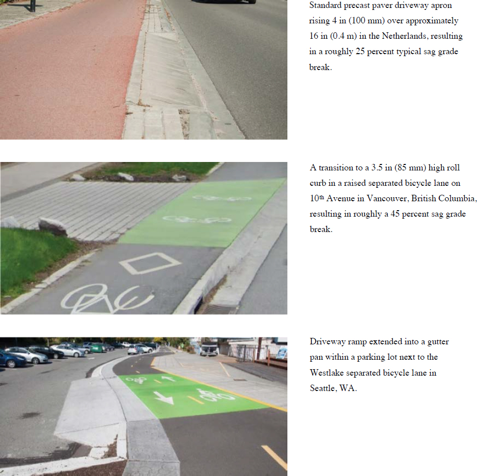
For typical 6-inch curb heights in North America, motor vehicle contact with the roadway surface typically occurs not in the middle of the vehicle underframe, but at the front or rear overhang of the vehicle. With only a slight drop in the standard 6- to 8-inch North American curb height, vehicle ground clearances can improve considerably and can tolerate much more aggressive grade breaks. With a dense separated bicycle lane network, the Dutch allow the use of a 4-inch curb to provide designers more flexibility to design driveway ramps to be relatively compact while providing an aggressive grade break (see Figure 25). For constrained North American scenarios, the adoption of this Dutch practice of using curb heights as low as 4 inches (100 mm) would be beneficial to improve safety and design outcomes in constrained locations, particularly on roadway segments with a high frequency of driveways. Another Dutch design option that could be considered for constrained cases where the gutter pan is not an integral component of the travel lane is to extend the driveway apron into the gutter pan to facilitate the desired design goals and minimally impact drainage flows, as shown in Figure 27.
4.6 Alley Design Considerations
Similar to driveways with different turning volumes and uses, alleys can serve diverse purposes and uses that could be considered in the design process. A common issue on streets without on-street parking or dedicated loading zones is that commercial deliveries for stores, pharmacies, small grocery stores, etc. often occur from the street, with the delivery vehicles blocking conventional or buffered bicycle lanes, which requires bicyclists to merge into adjacent travel lanes. Even with separated bicycle lanes, these types of larger deliveries often result in the delivery vehicle accessing and parking in the separated bicycle lane, or parking in the designated loading zone in line with on-street parking, but then blocking the bicycle lane with delivery equipment (e.g., ramps, delivery stockpiles).
Where these conditions are likely to occur, developers and designers could consider designing alleys to accommodate delivery operations and limit delivery conflicts to only the vehicles entering and exiting the alley. In these cases, alleys will often need to be wide enough to accommodate larger vehicles, and the entrances and exits to the alley must facilitate the turning movements of these larger vehicles as a control vehicle (often with some adjacent lane encroachment to accommodate the turning movement). Curb extensions and truck aprons, as well as designing the alley with a driveway apron, could all be considered to control passenger vehicle turning speeds better while still accommodating the desired larger control vehicle.
4.7 Mixing Zones or Undefined Transitions
Mixing zones in advance of intersections and transitions between different operations of separated bicycle lanes (i.e., two-way to one-way or contraflow) are both instances where the physical separation between the separated bicycle lane and the general travel lane may need to be discontinued for a limited duration of the bikeway. A factor not discussed in existing guidance is the presence of driveways within the functional area of an intersection, which can result in the removal of a significant portion or all the vertical separation from the driveways to the intersection. Similarly, an alley near multiple driveways may result in a midblock transition for bicyclists, which could be unexpected for all roadway users. This condition was only observed at one location in the study, and the result was a cluster of crashes (10) at both terminus points.
Not anticipating the need for mixing zones and transition areas or understanding the impact of access points during the bikeway selection process (see Section 2.2 and Section 3.4) may lead to safety issues in the implemented bikeway. Additionally, the desire to maintain on-street parking may result in transitions that are too short and do not meet minimum shifting or merging tapers for safety. It is important that designers avoid transitions that result in unconventional operations for users, require the application of too many traffic control devices to convey operational intent, or are overly ambiguous (Figure 28). In some cases, it may be appropriate or necessary to reconstruct the street to provide a raised sidewalk-level bicycle lane or to select a different bikeway type.
4.8 Lighting Design
A properly lit area creates a comfortable and functional environment for all street users. A well-lit street provides drivers with more opportunity to see bicyclists or pedestrians in the roadway or at approaching conflict points such as intersections and driveways and to stop or maneuver to avoid them. For bikeways, fixed-source lighting improves visibility along the path of travel, allowing bicyclists to better detect surface irregularities and obstructions at night.
At midblock locations, pedestrian-scale lighting is preferred to tall, highway-style lamps. Pedestrian-scale lighting is characterized by shorter light poles (approximately 15 ft high), lower


levels of illumination (except at conflict points such as intersections and driveways), closer spacing (to avoid dark zones between luminaires), and high-pressure sodium vapor, metal halide, or light emitting diode (LED) lamps.
For development projects that include new driveways crossing a bikeway or increase the number of parking spaces serviced by a driveway crossing a bikeway, the reviewing agency could consider requiring lighting to ensure that bicyclists will be more visible to approaching motorists.
4.9 Chapter Summary
This chapter provides a list of design considerations when installing separated bicycle lanes. The primary design elements affecting bicyclist safety midblock include bikeway and buffer design, sight distance, traffic control at driveway and alley crossings, and driveway designs. In addition to the design, the research team provides maintenance suggestions for each design element. Both qualitative and quantitative measures are summarized as follows:
- Bikeway width—Conventional bikeway width of 4 to 6 ft does not account for roadside fixed objects including vertical separation elements. Therefore, the research team suggests an extra 12 to 36 in for separated bicycle lanes to accommodate the bicyclists operating near vertical elements (this does not include the buffer zone where the vertical elements are usually installed).
- Buffer design—Buffer width, pavement marking, and spacing of vertical elements are important bikeway design considerations. The FHWA Bikeway Selection Guide recommends a minimum buffer width of 3 ft when the parking lane is located between the bicycle lane and the general travel lane (Schultheiss et al. 2019). The safety effectiveness of buffer pavement markings has not yet been evaluated. Consideration could be given to using pavement marking materials that have the longest lifespan while achieving the desired retroreflectivity and visibility performance characteristics over materials that may be cheaper to install but require frequent refreshing. Currently, there is no national guidance on where to place vertical elements within a bicycle lane buffer. Some agencies place vertical elements within the buffer as close as possible to the bicycle lane to minimize vehicle strikes to the vertical elements or to create additional space for vehicle doors to open without striking a vertical element. This practice results in less operating space for bicyclists. Most of the separated bicycle lanes evaluated in NCHRP Web-Only Document 414 utilized flexible delineators as vertical elements. Agencies may choose to implement separated bicycle lanes with more robust vertical elements such as doweled-in concrete barriers, modular concrete barriers, extruded or precast curbing, small medians with
- curbing, or fully raise these bikeways to sidewalk level during street reconstructions to create more protected bikeways and lower maintenance costs associated with less robust vertical elements.
- Sight distance—Guidance for drivers and bicyclists traveling on the street will differ based on the type of bicycle facility and the site conditions. The AASHTO Bike Guide (2023) provides new methods to evaluate sight distances for separated bicycle lane conditions based on stopping sight distances, motorist turning speeds, and typical bicycle operating characteristics. The recommended clear space based on vehicle turning speeds and turning radii are provided in Table 2. On-street parking spaces can also restrict the sight distance of vehicles entering the street from a driveway or alley. Agencies have existing guidance or regulations restricting on-street parking near driveways or intersections, such as restricting parking 5 ft, 10 ft, or 20 ft from the edge of the driveway. For corridors with commercial driveways spaced 100 ft apart or less, designers might consider eliminating on-street parking between these driveways in favor of maximizing sight distances.
- Traffic control—Using pavement markings and traffic signs at driveways or alleyways along midblock bikeway sections helps to raise awareness among motorists and bicyclists of conflict locations. Driveway and alley geometry and material choices can also signal right-of-way priority for motorists or crossing pedestrians and bicyclists. Some of the recommended practices and countermeasures are bicycle-related pavement marking symbols, chevrons, or shared lane markings, crosswalk markings, green-colored pavement, dotted white edge lines to define the crossing, supplemental yield lines to define the driveway location and yield points, longitudinal lines and gore zones to define the driveway approach area, centerlines in two-way bikeways, solid or dashed green paint, and markings encouraging slower bicyclist approach. There is no guidance on appropriate traffic signs that need to be implemented at uncontrolled locations to minimize conflicts between bicyclists and motorists. As a result, many communities have been deploying a wide range of treatments to raise awareness of motorists and/or crossing pedestrians and bicyclists at conflict points associated with driveways and alleys.
- Driveway design—The research team suggests using the Michigan DOT Sidepath Intersection and Crossing Treatment Guide (2018), which provides examples of traffic control applications based on driveway usage and creates three tiers of design options [minimal, low, and higher conflicts (Table 3)]. An example of such guidance applying the driveway volume guidance (Section 3.2) is presented in Figure 21. Overall, there is limited national guidance and research on the geometric design of driveways. The AASHTO Green Book lists objectives for driveway design, such as minimizing the width of the driveway that bicyclists and pedestrians must cross and designing a driveway shape that conforms to the path of the turning vehicle and minimizes encroachment into other lanes. However, the latter recommendation results in higher turning speeds. Motor vehicle design speed criteria at driveways need to always be as low as possible, preferably at or below 5 to 8 mph. Some of the geometric features of driveways that can help to achieve lower speeds are (1) horizontal geometry—designing driveway access that allows the control or design vehicle to use the full width of the driveway throat to complete a turn into or out of the driveway; and (2) vertical geometry—considering maximum sag grade breaks beyond the current practice of 9 percent (AASHTO 2018). Section 4.5 provides some national and international examples that could be considered for reducing the conflicts between motorists and bicyclists at driveways and alleyways.
- Alley design—Alley design could be considered at locations with frequent deliveries that may potentially block bicyclists’ paths at separated bicycle lanes (a very common occurrence at alley streets without on-street parking or dedicated loading zones). Where these conditions are likely to occur, developers and designers could consider designing alleys to accommodate delivery operations and limit delivery conflicts to only the vehicles entering and exiting the alley. In these cases, alleys will often need to be wide enough to accommodate larger vehicles, and the entrances and exits to the alley must facilitate the turning movements of these larger
- vehicles as a control vehicle. Curb extensions and truck aprons, as well as designing the alley with a driveway apron, could be considered to better control passenger vehicle turning speeds while still accommodating the desired larger control vehicle.
- Mixing zones—Mixing zones in advance of intersections and transitions between different operations of separated bicycle lanes (i.e., two-way to one-way or contraflow) are both instances where the physical separation between the separated bicycle lane and the general travel lane may need to be discontinued for a limited duration of the bikeway. A factor not discussed in existing guidance is the presence of driveways within the functional area of an intersection, which can result in the removal of a significant portion or all of the vertical separation from the driveways to the intersection. Similarly, an alley in close proximity to multiple driveways may result in a midblock transition for bicyclists (from a separated bikeway to a more conventional bicycle lane), which could be unexpected for all roadway users. This condition was only observed at one location in the study, and it resulted in a cluster of crashes (10) at both terminus points. Designers could avoid transitions that result in unconventional operations for users, require the application of too many traffic control devices to convey operational intent, or are overly ambiguous. In some cases, it may be appropriate or necessary to reconstruct the street to provide a raised sidewalk-level bicycle lane, or to select a different bikeway type.
- Lighting design—At midblock locations, pedestrian-scale lighting is preferred to tall, highway-style lamps. Pedestrian-scale lighting is characterized by shorter light poles (approximately 15 ft high), lower levels of illumination (except at conflict points such as intersections and driveways), closer spacing (to avoid dark zones between luminaires), and high-pressure sodium vapor, metal halide, or LED lamps. For development projects that include new driveways crossing a bikeway or that increase the number of parking spaces serviced by a driveway crossing a bikeway, the reviewing agency could consider requiring higher levels of lighting at the bikeway to ensure that bicyclists will be more visible to approaching motorists.


