Low-Impact Frog Design: Primer and Research Roadmap (2026)
Chapter: 3 Overview of Different Frog Designs

CHAPTER 3
Overview of Different Frog Designs
3.1 Rail-Bound Manganese Frogs
Description
The RBM frog is by far the most common type of frog in use in the track industry and is used in freight, commuter, rapid transit (subway), and light-rail transit applications. The first RBM frog was introduced in 1894 and consists of a solid manganese insert that is wrapped with milled sections of rail and then bolted, or in some cases epoxy bonded, together. The manganese steel insert is used because it can withstand severe impact. Since the introduction of manganese to special trackwork in the 1890s, no material has been found to be superior in terms of durability and cost (Frank 1986). Figure 3-1 shows a typical RBM frog in a turnout on ballast-and-tie track, and Figure 3-2 shows how the solid manganese insert is wrapped by the steel rail.
Noise and Vibration
FTA guidance assumes excess noise of 5 decibels (dB) within 300 feet (ft) from frogs, and excess vibration of 10 dB within 100 ft and 5 dB between 100 and 200 ft (FTA 2018). The excess noise and vibration is the difference in noise or vibration level generated at the frog compared to standard tangent track. Data presented in Appendix B shows that excess noise levels from RBM frogs quickly decrease with increasing distance from the track because general rolling noise radiated from the rail is greater than the impact noise generated near the frog point. Measured excess noise levels were about 5 dB within 12 ft of the frog but were close to 0 dB at 75 ft from the frog. Where the excess overall noise was 0 dB, impact noise from the frog was still perceptible due to the low-frequency content of the impact noise. The data in Appendix B shows measured excess vibration levels that typically vary between 10 and 15 dB for RBM frogs.
Operational Considerations
- Speed: Speed is restricted when traveling through the diverging route of a turnout because it can produce high lateral forces and accelerations at the switch and frog. The recommended speeds are based on the turnout geometry. Typically, the sharper the angle of the turnout, the lower the speed limit. The speed restrictions will depend on the standards adopted by the transit agency. TCRP Synthesis 107: Rail Transit Track Inspection Practices: A Synthesis of Transit Practice reports that some transit agencies have written their own standards, but most have adopted standards from FTA, FRA, APTA, or the California Public Utilities Commission (Zuspan 2013).
- Wheel profile: The standard AREMA RBM frog was designed for the AAR-1B wheel profile. However, many transit properties have agency-specific wheel profiles that vary the wheel diameter, tread width, and flange size. For optimal performance, the frog design should be matched

Long Description.
The Rail Bound Manganese frog features a solid manganese insert wrapped with milled rail sections. It is bolted or epoxy-bonded together, designed to withstand severe impacts.

Long Description.
The frog point and wing rails are evident, depicting the integration of materials. The steel rail encases the manganese component, providing structural support.
- to the wheel design. The standard AREMA-style RBM frog can be adjusted to perform better with custom wheel profiles.
- Reliability: The RBM frog design is a very reliable design—RBM frogs have no moving parts, and they are the most common frog design, making them familiar to all track maintainers.
Maintenance Considerations
- The most important maintenance activity for all frog designs is welding the frog when it begins to wear. Agencies need to track wear and develop standards for when action needs to be taken.
- All frogs require regular inspections. FTA guidance is for detailed inspections to occur once per month on mainline special trackwork. The detailed inspections should include good documentation of everything within the confines of the turnout.
- Regular tightening of loose bolts or fasteners is important.
Cost and Procurement
Because the RBM frog is the most common design, it is the easiest to procure. However, freight lines typically use much higher frog numbers compared to transit lines, so typical transit frogs may not be an “off-the-shelf item” from manufacturers. It is reasonable to expect a 1-year lead time for a transit RBM frog. The typical cost for a standard #10 RBM frog in 2025 is about $15,000. This approximate number is used as a base, and this primer suggests likely percentage increases for alternative low-impact frog designs. These costs are all approximate since prices fluctuate over time and between manufacturers or distributors. These approximate costs are based on experience and recent discussions and are for materials only; costs reported in this primer do not include labor.
Summary
The advantages and disadvantages of RBM frogs are summarized in Table 3-1.

Long Description.
The column headers are Pros and Cons. The data given in the table row-wise is as follows:
Row 1: Rugged for all loads and conditions; High impact loads generate wear and high noise and vibration levels.
Row 2: Easy to install and maintain; Welding is required over time.
Row 3: Standard design makes it easier to procure; Bolts may become loose and need re-tightening.
3.2 Movable-Point Frogs
Description
In a movable-point frog, the gap in the flangeway is eliminated by laterally moving the point of the frog in the direction corresponding to the direction of train travel. Figure 3-3 depicts the transition zone for movable-point frogs. Additional signaling cable provides a link between the switch and frog, and additional switching controls and machines are required at the frog. This extra equipment requires additional space in the right-of-way and additional maintenance. The cable link between the switch and the frog is lengthy and can be susceptible to damage. Frequent inspections and maintenance are needed for reliable operations of the movable-point frog.
The movable-point frog design is most suitable for locations where low noise and vibration levels are a priority because of the elimination of the gap in the frog flangeway in the tangent and diverging direction. Movable-point frogs are also a good option for acute or sharper angle frogs where the fixed flangeway gap would be wider (typically #16, #24, and #32 frogs). Movable-point frogs can allow for safer movement through a wider flangeway gap, especially at higher speeds.
Movable-point frogs are installed as the default frog on the Vancouver Skytrain system because of their wheel profile. Examples of U.S. transit agencies where movable-point frogs are installed to address specific design needs are Sound Transit, Los Angeles Metro, Chicago Transit Authority, and Miami Dade Transit.
Noise and Vibration
Movable-point frogs are considered the most effective frog design for eliminating the impact noise and vibration associated with fixed-point frogs in the tangent and divergent directions. The gap in the flangeway is eliminated by moving the point of the frog in the direction in which the train is moving. Excess noise and vibration from movable-point frogs is often considered to
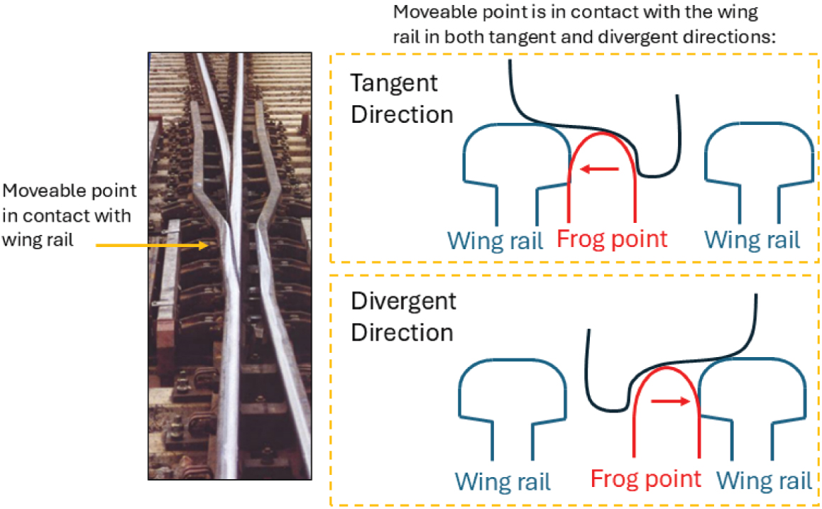
Long Description.
The photo shows the physical setup where the movable point contacts the wing rail. The illustration is titled 'Moveable point is in contact with the wing rail in both tangent and divergent directions.' It shows two scenarios, Tangent and divergent directions, each having a frog point between a wing rail on either side. In the tangent direction, the frog point is placed toward the left wing point. In the divergent direction, the frog point is placed toward the right wing point.
be 0 dB in environmental studies; however, the joints in the rail associated with special trackwork may produce some excess noise and vibration. Because of the expense of movable-point frogs and recent data presented in Appendix B showing that spring frogs with a closed gap do not minimize excess vibration, alternative vibration mitigation measures such as resilient fasteners or ballast mats under a conventional frog may be better solutions.
Operational Considerations
- Speed: Movable-point frogs are popular for higher-speed operations. Higher-number frogs allow for higher speeds in the diverging direction but also have a longer flangeway gap. The movable-point frog is used to close the gap in the flangeway.
- Vehicles/wheels: Movable-point frogs can likely be used with any vehicle or wheel profile. Agencies with particularly small wheel treads may prefer a movable-point frog because of concerns transitioning through the flangeway gap in fixed-point frogs.
- Signaling: If there are issues with the signaling equipment, train operators will need to know how to manually throw the switch of the movable-point frog. Outages of the signaling equipment may also affect the timing and reliability of service. The signaling link between the switch and frog is often lengthy and may be susceptible to damage.
Maintenance Considerations
- Added maintenance is required to keep the additional switch and signaling equipment in good working order. Extra maintenance requirements may include the following:
- Slide plates should be lubricated frequently, depending on use.
- The signal link between the switch and the frog should be inspected.
- All missing or damaged bolts should be replaced immediately.
- Wear measurements should be identified for all components, and remedial action should be established. Any metal flow should be removed. Braces must be kept tight, and the base of the rail must be seated correctly.
- Rail grinding is needed to control corrugation and maintain a good wheel–rail profile, or the noise and vibration benefits of the frog may not be achieved.
Cost and Procurement
Movable-point frogs generally cost about three times more than standard RBM frogs. Lead times are about 1.5 to 2 years. A switch machine must be linked to the frog points with signaling and synchronization with the switch. This is a large cost that could add up to $100,000 more than a standard frog including cables and labor. Because of the high cost and maintenance needs, movable-point frogs generally are installed only where low noise and vibration levels are required or where the geometry of the turnout results in wide flangeway gaps that may benefit from a movable point.
Summary
The advantages and disadvantages of movable-point frogs are summarized in Table 3-2.
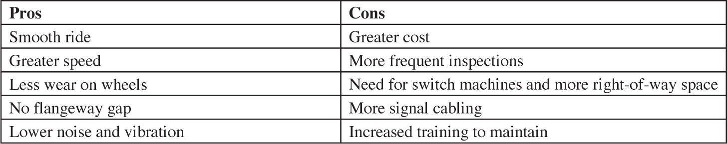
Long Description.
The column headers are Pros and Cons. The data given in the table row-wise is as follows:
Row 1: Smooth ride; Greater cost.
Row 2: Greater speed; More frequent inspections.
Row 3: Less wear on wheels; Need for switch machines and more right-of-way space.
Row 4: No flange-way gap; More signal cabling.
Row 5: Lower noise and vibration; Increased training to maintain.
3.3 Spring Frogs
Description
In a spring frog, the gap in the flangeway in the tangent direction is eliminated using a spring-loaded wing rail that keeps the wing rail in contact with the point of the frog. In the diverging direction, the normally closed frog is pushed open by the wheel flange, and the wheel will travel through a flangeway gap. Because the flangeway gap is closed only for the tangent direction, the low-impact effects are experienced only in the tangent direction. This frog design is most suitable for locations where diverging movements through the frog are rare. Figure 3-4 depicts the transition zone for spring frogs.
Spring frogs are installed in one location on the Los Angeles Metro as a noise and vibration mitigation measure. Spring frogs are also in service on the Chicago Transit Administration system but are being phased out because maintenance equipment cannot move through the frogs easily. In Chicago, these frogs were originally installed on express lines to improve ride quality where speeds are higher.
Noise and Vibration
Because spring frogs eliminate the gap in the flangeway for the tangent direction, they are often considered to fully eliminate the excess noise and vibration levels associated with RBM frogs in the tangent direction and perform similarly to RBM frogs in the diverging direction. However, measured levels for this study, presented in Appendix B, show noise and vibration levels like RBM frogs for train movements in the tangent direction (10 dB excess vibration and 5 dB excess noise at 12 ft from the frog and decreasing with distance). Based on the data presented in Appendix B, alternative vibration mitigation measures such as resilient fasteners or ballast mats under a conventional frog may be more effective solutions. Also, higher-speed trains running in the diverging direction may cause a very loud noise when the spring frog “slaps” back against the point.
Operational Considerations
- Speed: There are no speed restrictions when running in the tangent (mainline) direction, but there are speed restrictions for diverging moves consistent with RBM frogs.
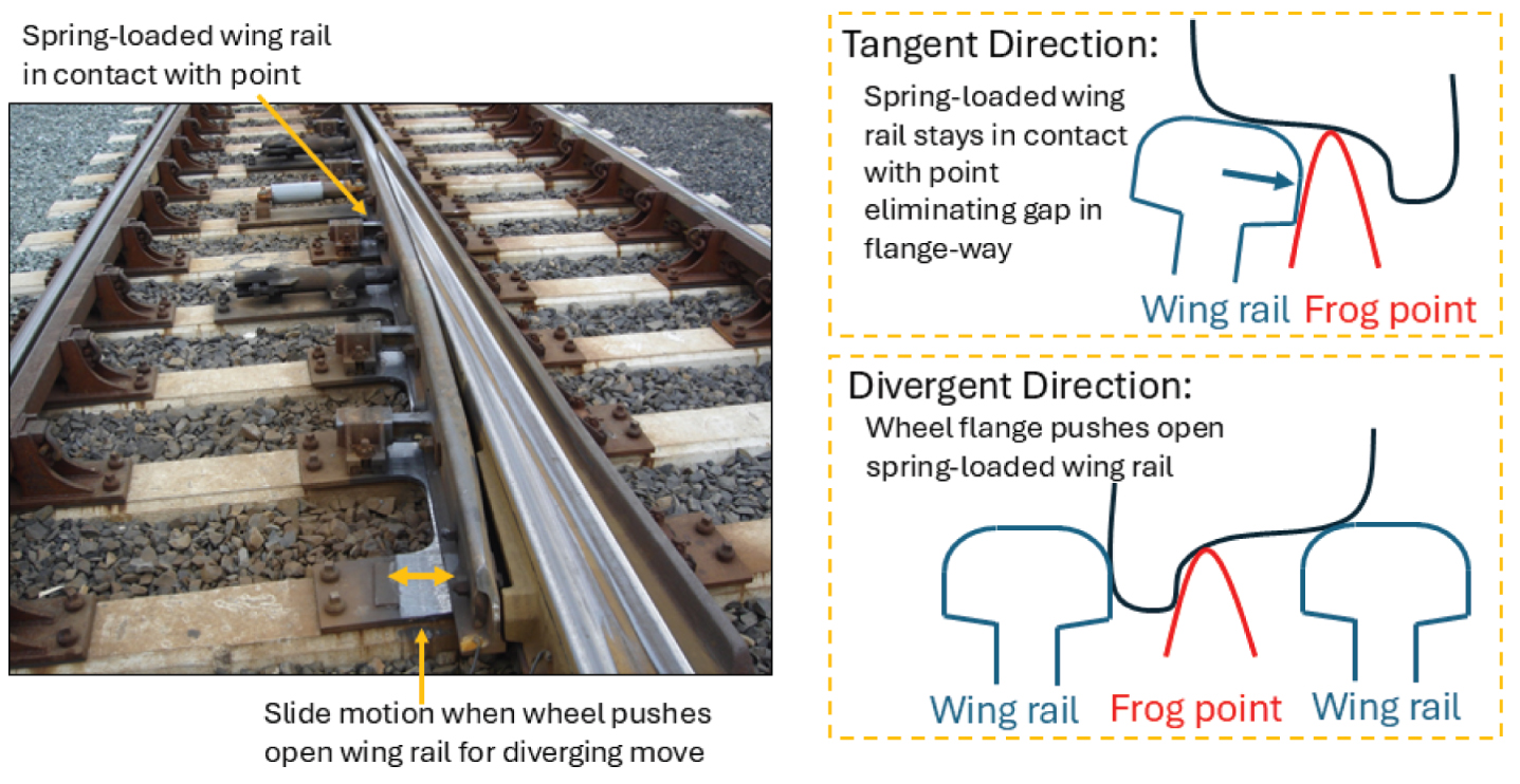
Long Description.
The view highlights the spring-loaded wing rail in contact with the point and the slide motion when a wheel pushes open the wing rail for the diverging move. The illustration details the tangent and divergent directions. In the tangent direction, the spring-loaded wing rail stays in contact with the point, eliminating the gap in the flangeway. In the divergent direction, the wheel flange pushes open the spring-loaded wing rail, creating a flangeway gap. Labels indicate the wing rail and the frog point and their interactions in both directions.
- Wheel profile: Certain wheel profiles may have difficulty pushing open the closed spring frog when moving through the diverging direction. Agencies should confirm with suppliers that their wheel profiles are compatible with a spring frog design before putting one in service.
- Vehicles: Lightweight vehicles often have issues reliably pushing open the frog spring rail in the diverging direction. Similarly, it can be difficult to optimize the spring-loaded wing rail for systems that run multiple vehicle types because different weights create reliability issues.
Maintenance Considerations
- Hi-rail vehicles usually cannot push open the spring-rail frog, thus creating issues for maintenance teams. This may lead to flange climb derailments, which can damage infrastructure and impact revenue service.
- Regular grinding is needed to control corrugation and maintain a good wheel–rail profile, or the noise and vibration benefits of the frog may not be achieved.
- It is extremely important that the movable wing rail is never higher than the frog point, or a derailment may occur; hence, it is very important to inspect the hold-down horns that keep the wing rail from lifting. This may require more frequent detailed inspections of spring frogs compared to conventional RBM frogs.
- A hollow wheel inadvertently can push the movable wing rail out and cause a derailment, a situation that demonstrates the importance of good wheel maintenance.
- Some designs have hydraulic pistons as opposed to springs that can be adjusted for pressure to allow less or more force to spring the wing rail. Occasionally this may need adjusting during maintenance activities. It is important for maintainers to understand the adjustment feature.
Cost and Procurement
Spring frogs generally cost two times more than a conventional RBM frog. Procurement can be an issue since most properties are phasing this type of frog out because of maintenance issues or safety concerns. There are no additional signaling or cables associated with the spring frog; however, there should be a point detection system to confirm that the wing rail has sprung back and made positive contact with the frog point. Installing a point detection system using a much smaller box may cost about $20,000 more. Procurement would be longer than the base of 1 year that is assumed for a conventional RBM frog.
Summary
The advantages and disadvantages of spring frogs are summarized in Table 3-3.
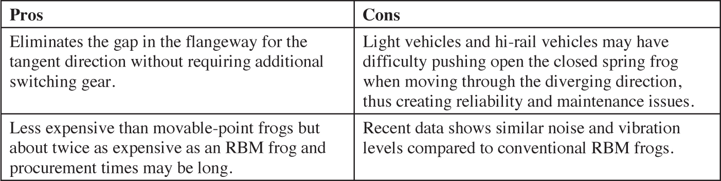
Long Description.
The column headers are Pros and Cons. The data given in the table row-wise is as follows:
Row 1: Eliminates the gap in the flangeway for the tangent direction without requiring additional switching gear; Light vehicles and hi-rail vehicles may have difficulty pushing open the closed spring frog when moving through the diverging direction, creating reliability and maintenance issues.
Row 2: Less expensive than movable point frogs but about twice as expensive as an RBM frog, and procurement times may be long; Recent data shows similar noise and vibration levels compared to conventional RBM frogs.
3.4 Flange-Bearing Frogs
Description
Flange-bearing frogs transfer the support from the wheel tread to the wheel flange using a ramp in the special trackwork while traversing the frog gap. Figure 3-5 shows a diagram of the flange-bearing frog transition zone where the wheel flange supports the wheel and results in the wheel tread being lifted over the point of the frog. Figure 3-6 shows two examples of street-running flange-bearing frogs. In Figure 3-6, the portion of the flangeway where the dirt has been worn away shows where the wheel has transferred from the tread onto its flange past the frog point in either direction.
The allowable operational speed through a flange-bearing frog depends on the length of the ramp. Higher-speed flange-bearing frogs require a longer ramp with a shallower slope, which requires more space for the frog. In Figure 3-6, the picture on the right shows that the wheel is traveling in the flangeway over a longer distance, indicating a longer ramp.
Flange-bearing frogs are popular in street-running systems where the wheel profiles may have narrow tread widths and continuous wheel support through the frog cannot be provided by the wheel tread. Street-running systems with flange-bearing frogs include Southeastern Pennsylvania Transportation Authority (SEPTA), Massachusetts Bay Transportation Authority (MBTA), Utah Transit Authority, and Toronto Transit Commission (TTC). Sound Transit has retrofit RBM frogs to be flange-bearing on its light-rail system as a noise and vibration mitigation measure.

Long Description.
The illustration shows the transition zone, highlighting the ramped flangeway that supports the wheel flange. This design lifts the wheel tread over the frog point, ensuring smooth passage. The frog point is marked, and the illustration shows the interaction between the wheel flange and the track structure.
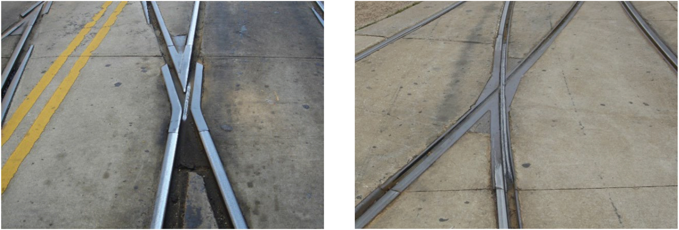
Long Description.
The two photos show examples of street-running flange-bearing frogs and depict how the wheel flange supports and lifts the wheel tread over the frog point. The right photo illustrates a longer flangeway.
Noise and Vibration
Flange-bearing frogs are generally considered to reduce noise and vibration from standard RBM frog designs by about half, which is excess noise of 2.5 dB within 300 ft of the frog and excess vibration of 5 dB. However, trains typically travel through flange-bearing frogs at low speeds, which makes it difficult to quantify their effect. Data shown in Appendix B was collected on flange-bearing frogs at SEPTA, but train speeds were 10 miles per hour (mph) or less. Also, the noise and vibration benefit depends on the maintenance status of the frogs. If the ramp in the flangeway is worn down too low, the rolling surface of the wheel will not successfully transfer from the tread onto the flange.
Operational Considerations
- Speed: The allowable operational speed through the frog depends on the slope and length of the flangeway ramp. TCRP Report 155: Track Design Handbook for Light Rail Transit, Second Edition recommends that the ramp ratio be no steeper than 1 divided by twice the design speed in kilometers per hour (Parsons Brinckerhoff, Inc., et al. 2012). Higher operational speeds require longer ramps, which can limit their applicability because of space constraints. Systems that need to conform to FRA regulations may face speed restrictions of 15 mph for flange-bearing frogs. Low-floor cars may also face additional speed restrictions.
- Wheel profile: For large amounts of flange-bearing special trackwork, wheel flanges should be designed to be flat or nearly flat to minimize metal flow. Flange-bearing frogs often are employed on systems with narrow wheel treads, where continuous wheel support through a standard RBM frog cannot be provided. Flange-bearing frogs may not be practical at agencies with wheel profiles that have short flanges because any flange wear will bring the flange length too close to the condemning limit.
- Safety/weather: There is a slightly elevated risk of derailment in freezing weather when ice can build up and cause the wheel to elevate above the top surface of the frog.
Maintenance Considerations
- The ramp must be measured during monthly inspections of the turnout to determine when the ramp needs to be adjusted or when weld material needs to be added. Ramps need to be consistently welded up to maintain the height necessary to transfer the wheel load from the tread to the flange.
- Rigorous wheel truing is needed to keep the flange height as uniform as possible. Flange height can increase with wheel tread surface wear.
- For street running systems, look for spalling concrete and road surface irregularities.
Cost and Procurement
Flange-bearing frogs generally cost roughly 30% more than a conventional RBM frog (roughly $20,000). Some manufacturers will simply add a filler piece into the standard mold to introduce a ramp into the casting. Flange-bearing frogs can likely be procured on the same 1-year lead time as conventional RBM frogs.
Summary
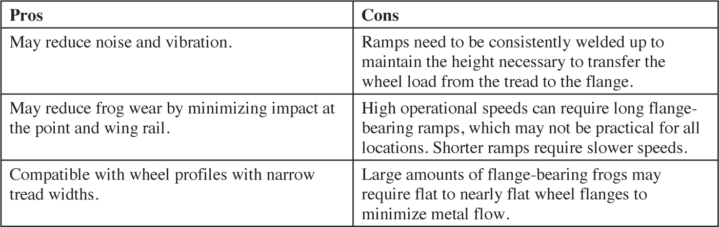
The advantages and disadvantages of flange-bearing frogs are summarized in Table 3-4.
Long Description.
The column headers are Pros and Cons. The data given in the table row-wise is as follows:
Row 1: May reduce noise and vibration; Ramps need to be consistently welded up to maintain the height necessary to transfer the wheel load from the tread to the flange.
Row 2: May reduce frog wear by minimizing impact at the point and wing rail; High operational speeds can require long flange-bearing ramps, which may not be practical for all locations. Shorter ramps require slower speeds.
Row 3: Compatible with wheel profiles with narrow tread widths; Large amounts of flange-bearing frogs may require flat to nearly flat wheel flanges to minimize metal flow.
3.5 Jump, Lift, or OWLS Frogs
Description
Jump frogs have standard, continuous rail in the tangent or mainline direction. On the diverging route, the flangeway and wing rail are ramped up to allow the wheel to pass over the mainline running rail head and open flangeway. A restraining guard rail is used on the wheel not making the “jump” to protect the direction of the raised wheel. Figure 3-7 depicts the transition zone for jump frogs.
Jump frogs can be very effective in locations where the diverging move is made very infrequently because the mainline direction has a standard rail profile without a gap, which eliminates all excess noise and vibration and allows for full-speed operations through the frog. Slow train speeds are required for diverging movements that jump over the main running rail. Alternative names for jump frogs are lift frogs, OWLS frogs, or unbroken mainline frogs.
These types of frogs are relatively new solutions for transit frogs. They have been adopted at TTC as the preferred frog for emergency turnouts, where the diverging direction is not often used. MBTA has installed these frogs on several crossovers, some of which have been in place
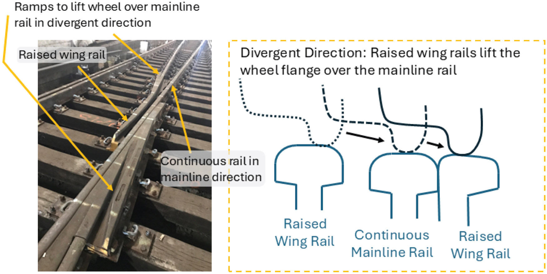
Long Description.
The photo and illustration depict the rail components and their functions in the divergent direction. The photo shows rail tracks with labeled components such as raised wing rail and continuous rail in the mainline direction. The illustration is titled 'Divergent direction: Raised wing rails lift the wheel flange over the mainline rail. It highlights the arrangement of a raised wing rail on either side of a continuous mainline rail.
for over 20 years. SEPTA has installed a jump frog on its street-running trolley system where the trolley line jumps over the freight tracks and has proven much more durable than their standard transit frog subjected to freight traffic.
Noise and Vibration
The jump frog will fully eliminate the excess noise and vibration from frogs in the mainline direction if properly maintained. There will be excess noise and vibration in the diverging direction, but increases are likely to be low because of the low train speeds for diverging moves. Diverging moves through jump frogs are typically limited to speeds of 10 mph. If diverging moves are used frequently, the wheel flange may cause damage to the head of the mainline rail, which could cause an increase in noise and vibration levels in the tangent (mainline) direction. Care should be taken to keep the top of the rail in good condition.
Operational Considerations
- Speed: There are no speed restrictions for the tangent, or mainline, direction. For diverging moves where the wheel must jump over the mainline rail, speeds may be restricted to no more than 10 mph.
- Wheel profile: The flange of the wheel must be able to support the dynamic forces of the jump. Narrow flanges and pointed flanges may not be effective in supporting these forces. Also, wheel profiles with short flanges may not be appropriate to use with jump frogs because they may not be able to accommodate much wear of the flange before reaching their condemning limit. The standard AAR-1B wheel profile can accommodate the jump frog, but many agencies use alternative profiles.
- Vehicles: Light-rail vehicles with low floors need to ensure there is not conflict with the raised guard required for the wheel not making the jump move.
- Reliability: Jump frogs are likely to be the most reliable and longest-lasting frog design for emergency turnouts that use the diverging move infrequently. The jump frog has proven to be the most reliable frog for use at SEPTA where their street-running trolley tracks intersect with freight tracks because the freight traffic sees a continuous rail running surface.
Maintenance Considerations
- Like flange-bearing frogs, the ramps in the jump frog need to be consistently welded up to maintain the height necessary to transfer the wheel over the mainline track.
- More frequent inspections are required to maintain proper use.
- Additional maintenance may be required on the head of the mainline rail if the jumping frog wheel flange is running on the mainline rail head.
Cost and Procurement
Jump frogs generally cost about 30% less than a standard RBM frog. Procurement could be less than an RBM. This cost assumes there are no impacts to the signal system or stray current; insulated joints may be needed on either side of the frog.
Summary
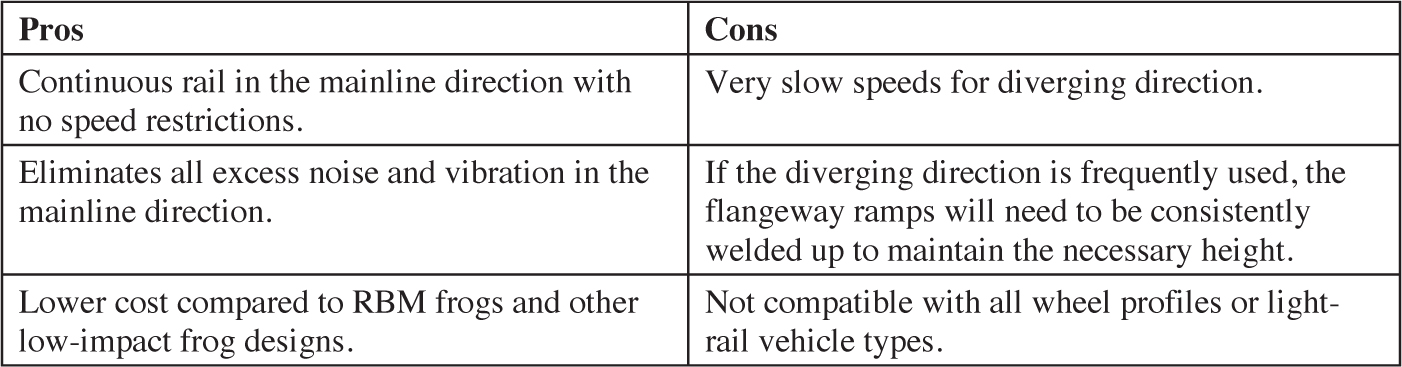
The advantages and disadvantages of jump frogs are summarized in Table 3-5.
Long Description.
The column headers are Pros and Cons. The data given in the table row-wise is as follows:
Row 1: Continuous rail in the mainline direction with no speed restrictions; Very slow speeds for diverging direction.
Row 2: Eliminates all excess noise and vibration in the mainline direction; If the diverging direction is frequently used, the flange-way ramps will need to be consistently welded up to maintain the necessary height.
Row 3: Lower cost compared to RBM frogs and other low-impact frog designs; Not compatible with all wheel profiles or light-rail vehicle types.


