Bridge and Tunnel Strikes: A Guide for Prevention and Mitigation (2025)
Chapter: 3 Bridge and Tunnel Strike Countermeasures
CHAPTER 3
Bridge and Tunnel Strike Countermeasures
Once an agency identifies factors that contribute to BrTS, the next step is to identify appropriate countermeasures to target the underlying issue or issues. The key to effectively addressing risk is to identify countermeasures that directly target the risk factors at hand to a level that is commensurate with the level of risk at the location of interest. For instance, if a bridge is at high risk of being struck and a bridge strike would have significant impacts on operations, then an agency might consider two options: raising the bridge height during the next bridge replacement or installing turnarounds. The result of this step is a list of potential options, not the final recommendation.
Agencies will benefit from diagnosing BrTS contributing factors before selecting countermeasures. By understanding the crashes and risk factors, agencies can target corrective measures and improve the cost-effectiveness of investments.
Systemic diagnosis involves network-level analysis to identify focus crash-types, focus facility-types, and risk factors (refer to Chapter 2, “Bridge and Tunnel Strike Risk Assessment,” for further details).
Site-specific diagnosis involves a review of site-specific crash history, traffic operations, and general site conditions.
Countermeasure selection starts with a larger list of options that are pared down to the preferred alternatives through more detailed analysis. This chapter focuses on the first part of the process—countermeasure identification. The next chapter focuses on the second part—alternatives analysis. This chapter begins with a discussion of general considerations and a summary of common BrTS risk factors with applicable countermeasures. The remainder of the chapter provides detailed descriptions of individual countermeasures, including cost, effectiveness, service life, and other considerations.
3.1 General Countermeasure Considerations
To inform countermeasure selection, agencies would consider the following (Atlanta Regional Commission 2022):
- Safe System principles: Countermeasures that align with Safe System principles are those that minimize the potential for crash frequency and severity, and build in redundancy (e.g., serve as a backup if another system component fails).
- Community context: Agencies should consider the surrounding land use, function of the roadway, and community context when selecting countermeasures. It is also useful to engage with the community to determine their wants and needs. Agencies can use public feedback to guide countermeasure selection and then justify the final selection with data-driven analysis.
- Multiple potential alternatives: It is desirable to identify and develop multiple potential countermeasures for comparison. This helps to identify the most effective and efficient option. It may be useful to develop a flow chart or decision matrix to assist practitioners in selecting appropriate countermeasures or mitigation strategies.
- Cost-effectiveness: Ideally, agencies would select a countermeasure that is highly effective at reducing the focus crash-type. Agencies should also consider construction and maintenance costs because more effective countermeasures (e.g., increasing clearance heights and widths) are often associated with higher costs.
- Service life: The Highway Safety Manual defines countermeasure service life as “the number of years in which the countermeasure is expected to have a noticeable and quantifiable effect on the crash occurrence at the site” (HSM 2010). Service life is used in benefit-cost analysis to convert annual costs and benefits to present values or vice versa. Understanding the countermeasure service life helps to account for the time value of costs and benefits, particularly when the analysis period is different from the service life or when the service life differs among alternatives.
3.2 Matching Countermeasures to BrTS Risk Factors
This section presents a summary of common BrTS risk factors with applicable countermeasures. The list of countermeasures and strategies includes bridge and tunnel design features, roadway design and operational characteristics, agency policies, oversize-vehicle routing systems, routing compliance for oversize loads, pilot car/escort vehicle guidance, and roadside and onboard vehicle technologies among others identified in the literature review.
Table 11 provides a summary of common BrTS risk factors and applicable countermeasures for on-bridge crashes. Table 12 provides a summary of common BrTS risk factors and applicable countermeasures for under-bridge or tunnel crashes.
3.3 Countermeasure Summaries
This section introduces six general categories of countermeasures: (1) passive systems, (2) sacrificial systems, (3) active systems, (4) vehicle-based systems, (5) nonphysical countermeasures, and (6) other tried strategies. Each countermeasure is then described in detail, including
Table 11. BrTS risk factors and applicable countermeasures for on-bridge crashes.
| On-Bridge Countermeasure | High Traffic Volumesa | Narrow Bridge Widthb | Bridge or Approach on Horizontal Curve | Bridge Lengthc |
|---|---|---|---|---|
| Advance warning signs and markings | — | ✓ | ✓ | ✓ |
| Horizontal alignment warning signs | — | — | ✓ | — |
| Changeable message signs (CMS) | — | ✓ | — | — |
| Flashing signs or beacons | — | ✓ | — | ✓ |
| Enhanced lateral clearance | ✓ | ✓ | ✓ | ✓ |
| Enhanced bridge and underpass lighting | ✓ | ✓ | ✓ | ✓ |
| High-friction surface treatment | ✓ | — | ✓ | — |
| Route surveys | ✓ | ✓ | ✓ | — |
| Pilot car/escort vehicle policies | ✓ | ✓ | ✓ | ✓ |
Note: —= Not a risk factor or not applicable.
Suggested thresholds (Hans, Bektas, and Phares 2016):
aTraffic volume > 400 vehicles/day (paved roads) or > 50 vehicles/day (unpaved roads).
bBridge width narrower than approach roadway (paved roads) or narrower than 20 ft (unpaved roads).
cBridge length > 150 ft (paved roads) or > 35 ft (unpaved roads).
Table 12. BrTS risk factors and applicable countermeasures for under-bridge or tunnel crashes.
| Under-Bridge or Tunnel Countermeasure | High Traffic Volumesa | High Heavy-Vehicle Volumes | Narrow Shoulder Width | Horizontal Curvature Present | Low Clearance Heightb | Narrow Tunnel Width | Abrupt Light Changes at Entrance/Exit |
|---|---|---|---|---|---|---|---|
| Advance warning signs and markings | — | ✓ | ✓ | ✓ | ✓ | ✓ | — |
| Horizontal alignment warning signs | — | ✓ | — | ✓ | — | — | — |
| Changeable message signs (CMS) | — | ✓ | — | — | ✓ | — | — |
| Flashing signs/beacons | — | ✓ | ✓ | ✓ | ✓ | ✓ | — |
| Bridge and tunnel fascia treatments | — | ✓ | — | — | ✓ | — | — |
| Hanging chains, strips, bells, or bars | — | ✓ | — | — | ✓ | — | — |
| Enhanced lateral clearance | ✓ | ✓ | ✓ | ✓ | — | ✓ | — |
| Enhanced tunnel lighting | ✓ | ✓ | ✓ | ✓ | ✓ | ✓ | ✓ |
| Enhanced bridge and underpass lighting | ✓ | ✓ | ✓ | ✓ | ✓ | — | ✓ |
| Transverse rumble strips | — | — | — | — | ✓ | — | — |
| Crash beams and portal frames | ✓ | ✓ | — | — | ✓ | — | — |
| Routing systems | — | — | — | — | ✓ | — | — |
| Early warning detection systems | — | — | — | — | ✓ | — | — |
| In-cab technology | — | — | — | — | ✓ | — | — |
| Connected vehicle technologies | — | — | — | ✓ | ✓ | ✓ | — |
| Subscription service | ✓ | — | — | ✓ | ✓ | ✓ | — |
| OHV and axle load restrictions | ✓ | ✓ | — | — | ✓ | — | — |
| OHV permits | ✓ | ✓ | — | — | ✓ | — | — |
| Vehicle checklists | — | — | — | — | ✓ | — | — |
| In-cab height placard | — | — | — | — | ✓ | — | — |
| Route surveys | ✓ | ✓ | ✓ | ✓ | ✓ | ✓ | — |
| Under-Bridge or Tunnel Countermeasure | High Traffic Volumesa | High Heavy-Vehicle Volumes | Narrow Shoulder Width | Horizontal Curvature Present | Low Clearance Heightb | Narrow Tunnel Width | Abrupt Light Changes at Entrance/Exit |
|---|---|---|---|---|---|---|---|
| Pilot car/escort vehicle policies | — | — | ✓ | — | ✓ | ✓ | — |
| Route atlas | — | — | — | — | ✓ | — | — |
| Commercial GPS policies | — | — | — | — | ✓ | — | — |
| Training and CDL certification | ✓ | ✓ | — | — | ✓ | — | — |
| Post-training/certification driver education and outreach programs | ✓ | ✓ | — | — | ✓ | — | — |
Note: — = Not a risk factor or not applicable; CDL = commercial driving license.
Suggested thresholds (Hans, Bektas, and Phares 2016):
aTraffic volume > 400 vehicles/day (paved roads) or > 50 vehicles/day (unpaved roads).
bClearance below bridges on freeways is typically 16 feet, 4 inches, and for overhead mounted signs it is 17 feet, 4 inches.
Low-clearance bridges and tunnels are defined here as having a vertical clearance of 14.5 feet or less at the lowest point.
the approximate cost, effectiveness, service life, and other considerations, such as where to use them and, where applicable, potential enhancements. The section concludes with a discussion of data quality improvements that can support a wide range of decisions, including the identification of high-priority locations, diagnosis of risk and crash contributing factors, selection of appropriate countermeasures, and evaluation of past investments.
Passive Systems: The purpose of these countermeasures is to improve driver awareness of bridge and tunnel restrictions through warning signs and enhanced delineation. Additional passive mitigation measures are provided to reduce crash severity. Height warning signing shows the clearance of the bridge or tunnel; sometimes these signs flash. Signing information is almost always 3 inches less than actual clearance, but this can vary from state to state. Inconsistencies among states may lead to inconsistent driver behaviors (e.g., states that give a larger margin of error may lead to drivers taking more risk in their decision to try to pass under the bridge). There is an opportunity to standardize this practice nationally to improve driver expectancy and behavior, especially when hauling across state lines. The following countermeasures are categorized as passive systems:
- Advance warning signs and markings.
- Horizontal alignment warning signs.
- Changeable message signs (CMS).
- Flashing LEDs within signs.
- Bridge and tunnel fascia treatments.
- Hanging chains, strips, bells, or bars.
- Enhanced lateral clearance.
- Enhanced tunnel lighting.
- Enhanced bridge and underpass lighting.
- Transverse rumble strips.
- High-friction surface treatments (HFST).
Sacrificial Systems: The purpose of these countermeasures is to reduce structural damage to bridges and tunnels through impact-absorbing systems installed on the face of the structure.
This countermeasure is intended to reduce structural damage if a BrTS incident occurs but often causes significant damage to the colliding OHV. A collision with traditional sacrificial systems may also scatter debris that could injure nearby road users. Sacrificial systems include the following:
- Crash beams and portal frames.
- Crash beams, installed on the face of a bridge or tunnel structure, are generally comprised of steel plates, I-beams, or a combination of both. This is intended for low-speed roads.
- Portal frames, installed as a separate structure in front of a bridge or tunnel structure, are generally composed of steel plates, I-beams, or a combination of both. This is intended for low-speed roads.
- Energy-dissipative system.
- This system combines a box beam with energy-absorbing materials (e.g., aluminum honeycomb) for the protection of bridge girders from overheight impacts.
Active Systems: The purpose of these countermeasures is to improve driver awareness of bridges and tunnels through detection- or location-based warning systems. These include the following:
- Routing systems.
- Early warning detection systems.
- Height detection systems: OHV detection (OHVD) systems have many ways of telling if a vehicle is too tall, such as LADAR (LAser Detection And Ranging) technology or a breaker beam setup. These detection systems work in conjunction with flashing signing typically to warn the driver.
- Smart Roadside commercial motor vehicle monitoring.
- License plate camera recognition system.
- Structure monitoring systems.
Vehicle-Based Systems: The purpose of these countermeasures is to improve driver awareness of bridge and tunnel restrictions through technology. The following is a list of vehicle-based systems.
- In-cab technology [e.g., CB (citizen band) radio warning systems].
- Connected vehicle technologies: Uses signal towers placed throughout the highway and provides individual trucks with real-time updates from transportation managers. This system lets drivers know about upcoming weather, hazardous conditions, road work, and other issues.
- Subscription service: Allows trucking managers to put in safety zones that warn the driver of obstacles or warnings. This system also detects driver speed and location for management information.
- Raised dump body light-and-sound warning system.
- Truck-mounted systems to monitor vehicle load.
Nonphysical Countermeasures: The purpose of these countermeasures is to improve driver awareness of bridges and tunnels through institutional policies, permitting procedures, outreach, and driver education programs.
- OHV and axle load restrictions: A restricted (R-posted) bridge does not have the reserve capacity to accommodate vehicles over the legal weight but can still safely carry legal weights. These bridges are identified with signing stating, “No Trucks with R Permits.”
- OHV permits: A permit authorizes the movement of an oversize and/or overweight vehicle for a specific time on permissible hauling days. Applications are required, and the permit will identify restrictions and an approved route.
- Vehicle checklists: Checklists should include measuring the height and width of trucks as well as engine and cab inspection. Checklists increase the driver’s awareness of the vehicle constraints, reducing incidents.
- In-cab height placard: Adjustable placards show the height of the truck (including cargo) in the cab for reference while driving in the event that a low-clearance sign is present. Drivers should compare the signing to the placard to ensure the truck can make it under.
- Route surveys: Advance drive-throughs of the route in question are taken using a pole or other measuring stick to identify any particular issues on the route. This is typically done by the carrier to confirm specific types of loads that may be repetitive or by an escort vehicle company trained to recognize potential infrastructure and navigational issues in conjunction with intended load specifications.
- Pilot car/escort vehicle policies.
- Road atlas: All low-clearance bridges on any highway or local road are displayed for drivers to reference. Drivers should be using this in conjunction with other navigation software.
- Commercial navigation system policies: Unlike typical navigational tools, specific applications for the trucking industry include routing that addresses vertical and horizontal clearances.
- Training and commercial driver’s license (CDL) certification: Training ensures a truck driver is knowledgeable about driving larger vehicles and informs them of dangers that come with the career. The certification is mandatory for all commercial trucking.
- Post-training/certification driver education and outreach programs: These programs provide material to insurance companies, industry organizations, motor carriers, and drivers with license renewals.
Data Quality Improvements: Improving the reliability and accessibility of data promotes informed decisions, including the OHV permitting process. For instance, there is a need to accurately describe the load size; the permitting process will not provide an optimal route without an accurate load size. There is also a need for agencies to maintain complete and up-to-date inventory data for structure size and roadway conditions (e.g., a 3-inch overlay causes a 3-inch reduction in vertical clearance). Finally, there is a need for accessible data; some states do not provide this readily. There is an opportunity to leverage the use of burgeoning data exchanges to share and broadcast updated information, including information on the location of work zones and related restrictions.
Passive Systems
The purpose of these countermeasures is to improve driver awareness of the presence and characteristics of bridges and tunnels through warning signs and enhanced delineation. Additional passive mitigation measures can reduce crash severity. The following countermeasures are categorized as passive systems:
- Advance warning signs and markings.
- Horizontal alignment warning signs.
- Changeable message signs (CMS).
- Flashing signs/beacons.
- Bridge and tunnel fascia treatments.
- Hanging chains, strips, bells, or bars.
- Enhanced lateral clearance.
- Enhanced tunnel lighting.
- Enhanced bridge and underpass lighting.
- Transverse rumble strips.
- High-friction surface treatments (HFST).
Advance Warning Signs and Markings
Description
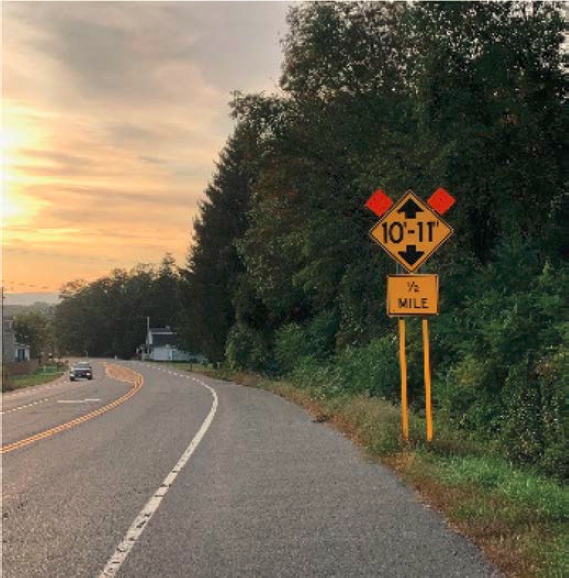
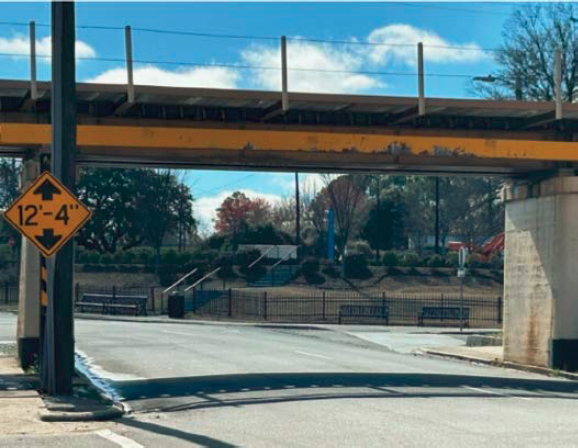
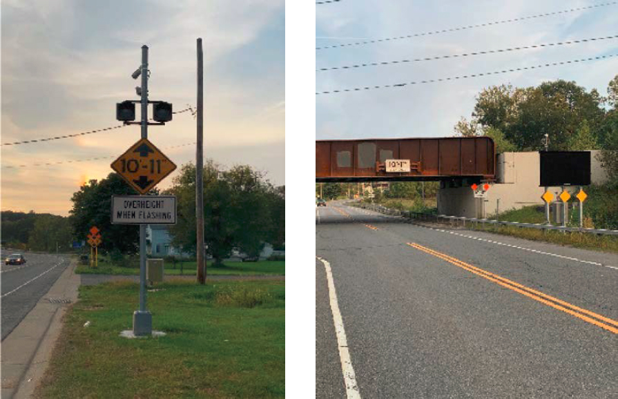
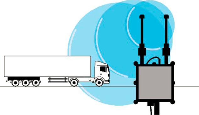
Low-clearance advance warning signs (W12-2) are required for “vertical clearances less than 14 feet 6 inches, or vertical clearances less than 12 inches above the statutory maximum vehicle height, whichever is greater” (MUTCD 2023). When required, clearance height shall be posted in advance of the structure. In addition, a low-clearance overhead sign (W12-2a or W12-2b) may be installed on the structure to supplement the advance warning sign (Figure 23 and Figure 24). Advance warning signs may include low-clearance warnings, specific clearance heights, and other relevant information to warn drivers of an upcoming low-clearance or narrow bridge or tunnel structure. Advance signing could also include directional components (e.g., truck detour or exit) to guide OHVs to another roadway.
Where to Use
Consider advance warning signs for use on all bridge and tunnel approaches based on engineering judgment, even when not required or recommended by the Manual on Uniform Traffic Control Devices (MUTCD). Advance warning signs should be located at a sufficient distance before the bridge to allow drivers to detour, turn around, or stop. Refer to Section 2C.25 of the

MUTCD for specific provisions (MUTCD 2023). Illumination and reflectivity are critical to ensure nighttime visibility.
Agencies should consider the following factors when assessing the potential use of advance warning signs.
- Clearance height at structure: Height measurements should be reviewed any time pavement thickness changes below the structure. Rutting or other pavement deformations should also be investigated, as vertical deflections may encroach on provided vertical clearances. The MUTCD requires low-clearance signs “to warn road users of vertical clearances less than 14 feet 6 inches, or vertical clearances less than 12 inches above the statutory maximum vehicle height, whichever is greater” (MUTCD 2023).
- Alternate routes: If heavy vehicles are not accommodated by the structure height, consider alternate route signing upstream of the last exit point before the structure. Additional regulatory signs such as “NO COMMERCIAL VEHICLES” or “NO TRUCKS” may be needed at upstream entry points to prohibit large vehicles from using the road.
Safety Effectiveness
Passive signing is estimated to be 10% to 20% effective in reducing BrTS incidents (Cawley 2002).
Enhancements
Agencies can consider the following enhancements to advance warning signs and markings:
- Flashing beacons.
- Doubled-up (i.e., signs on both sides of the road) or oversize signs.
- Repeating warning signs on the approach to the structure.
- In-lane retroreflective pavement markings such as “LOW BRIDGE” or “NO TRUCKS.”
- Transverse rumble strips.
- Hanging chains, strips, bells, or bars in conjunction with low-clearance warning signs located on entry ramps upstream of the structure.
- Pull-over areas directly upstream of the structure to allow OHVs to safely stop and wait for rerouting instructions or a police escort.
- Alternate route signing installed at entrance ramps or similar upstream of the structure.
Another opportunity is to explore the effectiveness and comprehension of traditional warning signs, particularly for non-English speaking drivers. The concern is that non-English speaking drivers may not understand low-clearance warning signs. This is a specific concern for areas near ports and international borders and in jurisdictions where multiple languages are common. Future research could explore driver comprehension of different warning signs such as signs that indicate the specific height restriction (e.g., 11′-6″) versus “LOW BRIDGE” or “NO TRUCKS.” The research could also explore the effectiveness of providing supplemental signs with multiple languages or units of measure (metric). Note the current MUTCD does not have provisions for the use of multilingual signs (MUTCD 2023); research in this area would support future rulemaking on MUTCD updates.
Costs and Service Life
Static signs and markings are relatively low cost and can typically be installed using maintenance resources. FHWA’s Countermeasure Service Life Guide estimates a service life of 15 years for new sign installations (Himes et al. 2021). The Vermont Agency of Transportation (VTrans) notes that “agencies should monitor the retroreflectivity of the signs. Regular washing is recommended to maintain reflectiveness” (VTrans 2023).
Static signs are relatively low cost, starting around $500 per sign.
More Information
The relevant provisions are contained in Section 2C.25 of the 11th edition of the MUTCD (https://mutcd.fhwa.dot.gov/pdfs/11th_Edition/Chapter2c.pdf) (MUTCD 2023).
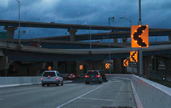
Horizontal Alignment Warning Signs
Description
Advance horizontal alignment “warning signs warn drivers that the horizontal road alignment is changing ahead, which may require speed reduction and careful attention. In-curve warning signs (such as chevrons) delineate the outside edge of the road on curves and reinforce the intended path of travel” (MUTCD 2023). Bridges and tunnels with curves on or within the structure or on the approaches may benefit from advance horizontal alignment warning signs.
Where to Use
Agencies can consider multiple advance horizontal alignment warning signs and the chevron alignment signs (W1-8) shown in Figure 25, on any road, bridge, or tunnel where horizontal curves are not readily expected or visible for drivers, or where there is already a history of roadway departure crashes (MUTCD 2023). The MUTCD either recommends or requires devices to indicate a change in horizontal alignment depending on the roadway type and traffic volume. The selection of devices, such as curve warning signs, is based on the speed differential between the advisory speed for the horizontal curve and the posted speed limit, statutory speed limit, or the 85th percentile speed on the approach to the curve (MUTCD 2023). Refer to MUTCD (2023) Table 2C-4B and Table 2C-6 in Section 2C for specific provisions on sign selection and the use of an advisory speed plaque based on the estimated speed differential. Note that consistency in messaging across similar sites is critical for establishing driver expectancy and promoting effective roadway operations (VTrans 2023).

Safety Effectiveness
Chevrons reduce nighttime crashes on curves by 25% [CMF (Crash Modification Factor) Clearinghouse ID 2438 (Srinivasan et al. 2009a)] and nonintersection fatal and injury crashes by 16% [CMF Clearinghouse ID 2439 (Srinivasan et al. 2009b)].
Enhancements
Agencies can consider the following conspicuity enhancements to horizontal alignment warning signs at bridges and tunnels. VTrans notes these conspicuity enhancements “are intended for implementation with an incremental approach based on local site conditions, funding, and engineering judgment” (VTrans 2023).
- A one-direction large arrow sign (Figure 25, W1-6) may be used either as a supplement or alternative to chevron alignment signs or delineators in order to delineate a change in horizontal alignment.
- For safety improvements on curves with existing warning signs, consider oversize and/or doubled-up (i.e., signs on both sides of the road) advance warning signs. Refer to MUTCD Table 2C-2 for conventional and oversize sign dimensions (MUTCD 2023).
- Retroreflective strips (same color as the sign background color) on signposts can be added to existing or new signs when the desired effect is not achieved.
- Fluorescent yellow reflective sheeting can improve conspicuity, particularly in areas with frequent fog or shadows.
- Flashing beacons can help draw attention to signs but should be used sparingly because drivers may tend to ignore devices that are overused.
Costs and Service Life
FHWA’s Countermeasure Service Life Guide estimates a service life of 15 years for horizontal alignment warning signs (Himes et al. 2021). VTrans notes that “agencies should monitor the retroreflectivity of the signs and regular washing is recommended to maintain reflectiveness” (VTrans 2023).
Static signs are relatively low cost, starting around $500 per sign.
More Information
“Enhanced Delineation for Horizontal Curves” (FHWA, n.d.-b).
Changeable Message Signs
Description
CMSs—also called variable message signs, digital message signs, matrix signs, or variable message boards—are digital traffic control devices capable of relaying short messages to drivers (Figure 26). They are often installed upstream of low-clearance structures in conjunction with additional warning devices. Low-clearance bridges and tunnels are defined here as having a vertical clearance of 14.5 feet or less at the lowest point.
Where to Use
Consider overhead or roadside CMS installations for low-clearance or narrow bridge and tunnel structures based on engineering judgment. Messaging should follow applicable MUTCD provisions. Agencies can consider the following factors when assessing the potential use of CMS systems:
- Power source: Permanent CMS system installations require power, which may be wired to direct connections or solar powered depending on the manufacturer.
- Flexibility: Unlike static signs, CMS systems can be programmed to display additional information as needed, such as AMBER alerts, emergency Homeland Security messages, transportation-related messages, or other safety-related information.
Safety Effectiveness
CMS systems are estimated to be 10% to 20% effective in reducing BrTS incidents.
Enhancements
CMS systems are often used in conjunction with active systems, such as early warning detection systems that estimate the height of approaching vehicles and provide real-time feedback for drivers using CMS or other methods.
Costs and Service Life
FHWA’s Countermeasure Service Life Guide estimates a typical service life of 10 years for a CMS (Himes et al. 2021).
Costs depend on the power source, mounting type/location, and length of need for underground conduits. As a starting point, CMS installations may cost around $45,000 per sign.
More Information
Manual on Uniform Traffic Control Devices (MUTCD 2023).
Flashing LEDs Within Signs
Description
Flashing LEDs within signs consist of intermittent lights surrounding or embedded in a sign to increase the conspicuity of the sign. These are considered a conspicuity enhancement and may be most beneficial under nighttime operation (Figure 27).
Where to Use
This conspicuity enhancement can be used with any warning signs (e.g., horizontal alignment warnings, low clearance, or narrow structure warnings), particularly under nighttime operations. Illumination and flashing rates should follow MUTCD Chapter 2A provisions (MUTCD 2023). Agencies can consider the following factors when assessing the potential use of flashing signs:
- Power source: Permanent installations require power, which may be wired to direct connections or solar depending on the manufacturer.
- Mounting location: Signs may be mounted overhead or on a roadside post. Flashing LEDs are installed as part of the sign.
Safety Effectiveness
Research is not yet available for applications of flashing signs/beacons as BrTS countermeasures.
Enhancements
None applicable at this time for this system.
Costs and Service Life
FHWA’s Countermeasure Service Life Guide estimates flashing warning signs have a service life of approximately 10 years (Himes et al. 2021).
Costs depend on the power source, mounting type/location, and length of need for underground conduits. As a starting point, flashing signs may cost around $15,000 per sign.
More Information
Low-Cost Treatments for Horizontal Curve Safety 2016, Chapter 4 (Albin et al. 2016).
Bridge and Tunnel Fascia Treatments
Description
Bridge and tunnel fascia treatments provide high-visibility delineation on the face of the lowest structural elements to visually reinforce low clearances. They are generally continuous installations of retroreflective material across the entire structure (Figure 28). As they are located on the structure itself, they are used as a supplemental countermeasure in conjunction with advance low-clearance warning signs. Bridge and fascia treatments are not a substitute for MUTCD signage.
Where to Use
Consider bridge and tunnel fascia treatments at all such structures based on engineering judgment.
Safety Effectiveness
Research is not yet available for applications of bridge and tunnel fascia treatments as BrTS countermeasures.
Enhancements
Agencies can consider the following enhancements to fascia treatments:
- Advance warning signs, flashing beacons, CMS systems, or other messaging devices; and
- Transverse rumble strips.
Costs and Service Life
Painted fascia treatments are generally low cost at around $20 per linear foot and are expected to have a service life of 20 to 25 years; however, cost and service life will vary depending on materials, humidity, and length of need. Regular maintenance is recommended to maintain reflectivity and visibility.
More Information
“Bridge Strike Mitigation” (NYC 2009).
Hanging Chains, Strips, Bells, or Bars
Description
Hanging metal chains, strips, bells, or bars, also known as telltale signs, provide auditory feedback upstream of the bridge or tunnel to warn drivers if their vehicle height exceeds the minimum vertical clearance provided at the structure. These systems consist primarily of an overhead structure with chains, strips, bells, or bars that hang down and terminate at the minimum clearance height for the bridge or tunnel structure downstream (Figure 29). OHVs strike the system and receive loud feedback while the corresponding signing warns them of the likely BrTS collision ahead.
Where to Use
Consider this countermeasure upstream of low-clearance bridge and tunnel structures based on traffic speeds, traffic volumes, OHV BrTS crash history, and engineering judgment. Low-clearance bridges and tunnels are defined here as having a vertical clearance of 14.5 feet or less at the lowest point. Agencies should consider the following factors when assessing the potential use of hanging chains, strips, bells, or bars:
- Traffic speeds: Ambient noise tends to increase as vehicle speeds increase, which in turn diminishes the feedback provided by this countermeasure. Installations perform best when
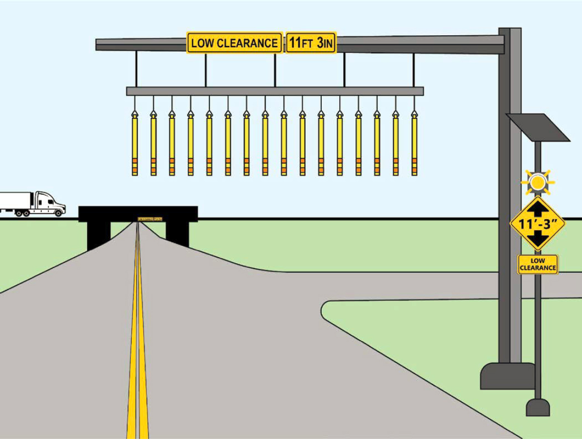
- Entrance ramps: One or more upstream entrance ramps may be suitable locations for these installations to alert OHVs far from the structure to provide time to react and give the driver the opportunity to exit the roadway, ideally, while they are traveling at lower speeds than on the approach to the structure.
vehicle speeds are very low (Caltrans 2019). As travel speeds increase, the propensity for damage to vehicles, occupants, and surrounding road users also increases.
Safety Effectiveness
Research is not yet available on the safety effectiveness of hanging chains, strips, bells, or bars.
Enhancements
Agencies can consider the following enhancements to hanging chains, strips, bells, and bars:
- Upstream signing is recommended to warn drivers of the upcoming device.
- Downstream signing is recommended to communicate why the vehicle struck the device and to provide route guidance to divert the vehicle away from the low-clearance structure.
Costs and Service Life
Using overhead sign installations as a surrogate, FHWA’s Countermeasure Service Life Guide estimates a service life of 15 years (Himes et al. 2021). Hanging chains, strips, bells, or bars may be damaged when struck by an OHV. Regular maintenance and timely replacement of broken members are recommended to maximize effectiveness and service life. One project in San Antonio, Texas, cost approximately $55,000 to install a pair of hanging chains with high-visibility PVC pipes at a low-clearance bridge (City of San Antonio 2017).
Enhanced Lateral Clearance
Description
When shoulder width on the approach differs from shoulder width provided at a bridge or tunnel structure, BrTS incidents are more likely to occur. This situation is common, as physical constraints are often more restrictive for the structure than on the approaches (Figure 30). Increasing lateral clearance between the edge of the travel lane and the face of the structure may reduce BrTS incidents.
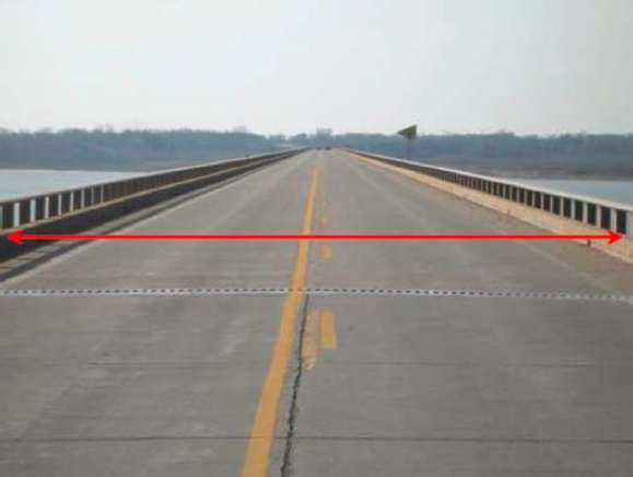
Where to Use
Consider increasing lateral clearance to bridge and tunnel walls/barriers at horizontal curves or locations with a history of roadway departure crashes. Enhanced lateral clearance to walls/barriers can provide recovery space for drivers who leave the travel land and therefore may reduce roadway departures crashes.
Safety Effectiveness
Narrow shoulders and proximity to barriers promote slower speeds but may increase the potential for barrier strikes. Research has shown that bridge width should include at least 3 feet of shoulder on both sides of the road or at least one-half the shoulder widths on approach roadways, whichever is greater. One study estimated the crash rate increases by approximately 60% if the total shoulder width drops from 6 feet (i.e., the desirable minimum) to 3 feet; in contrast, increasing the total shoulder width from 6 feet to 9 feet decreases the estimated crash rate by approximately 42% (Mak 1987).
Enhancements
None applicable at this time for this system.
Costs and Service Life
FHWA’s Countermeasure Service Life Guide estimates bridge widening has a service life of 30 years (Himes et al. 2021). Costs can vary significantly based on bridge type, estimated increase in bridge width, and site-specific design parameters.
More Information
Mitigation Strategies for Design Exceptions, Chapter 3 (Stein and Neuman 2007).
Enhanced Tunnel Lighting
Description
Crashes near tunnel entrances and exits tend to be more severe than crashes along the interior zones, and abrupt changes in lighting may be a contributing factor. Lighting transitions from light to dark conditions are especially difficult for older drivers as this aspect of vision tends to degrade over time.
Enhanced tunnel lighting targets two components—the roadway and the walls (Figure 31). Tunnel lighting may be improved by implementing zonal lighting and differing daytime and
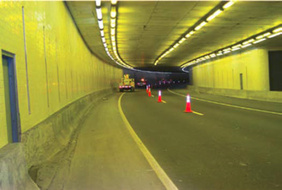
nighttime lighting plans. Recommendations for roadway and wall lighting for varying tunnel lengths and each region of the tunnel are provided in the 2023 FHWA Lighting Handbook (Gibbons et al. 2023).
Where to Use
All tunnels may benefit from lighting. This is especially critical where continuous roadway lighting is already provided upstream and/or downstream of the structure, in tunnels with pedestrians or cyclists, or where unusual or difficult geometry exists in the tunnel or on the approaches. Agencies can consider the following factors when assessing the potential to use tunnel lighting.
- Location: Particularly for low-clearance tunnels (a vertical clearance of 14.5 feet or less at the lowest point), lighting should not be installed on the bottom of the lowest structural elements to avoid encroaching on provided vertical clearances.
- Presence of horizontal curves: Horizontal curves require alignment changes, which may lead to roadway departure crashes; improving lighting through curves may reduce these crashes.
- Nighttime crashes: A nighttime lighting study can help determine the adequacy of illumination along the structure and approaches. Consider improving lighting around related signs and other warning features upstream of the structure. The 2023 FHWA Lighting Handbook contains information regarding appropriate light placement and illumination levels for maximizing visibility of pedestrians, signs, and other vertical obstructions (Gibbons et al. 2023).
- Daytime crashes: A daytime lighting study can help evaluate the ambient light inside the tunnel. According to the 2023 FHWA Lighting Handbook, daylight extends approximately 25 feet into the tunnel from the entry portal and roughly 50 feet inward from the exit portal (Gibbons et al. 2023). Any remaining tunnel length may warrant illumination, especially if the tunnel is longer than the calculated stopping sight distance for the travel speeds.
Safety Effectiveness
The CMF Clearinghouse does not include quantitative estimates of the safety impacts of improved tunnel lighting.
Enhancements
Agencies can consider the following enhancements to tunnel lighting:
- Headlight requirements for all drivers in the tunnel (both day and night).
- Painting the walls white may enhance tunnel lighting.
- Horizontal bands or patterns of light sources or reflective material installed along tunnel walls may improve visibility of pedestrians or other vertical objects and may also improve delineation of horizontal curves, if present.
- Varying illumination levels, type of lighting, color, or other parameters at different points along the structure may be beneficial depending on tunnel design and length. Refer to the 2023 FHWA Lighting Handbook for more information on lighting requirements for each zone of a tunnel (Gibbons et al. 2023).
Costs and Service Life
Tunnel lighting should be regularly inspected and maintained to ensure continuous, effective operation. FHWA’s Countermeasure Service Life Guide estimates lighting installation has a service life of 15 years (Himes et al. 2021).
Costs and service life vary depending on lighting manufacturer, power source, and road closure restrictions. One project in Colorado on US-550 cost roughly $675,000 for tunnel lighting upgrades to LEDs in 2018 (Colorado DOT, n.d.). On the higher end, in the Ted Williams Tunnel in
Boston, Massachusetts, tunnel lighting was upgraded to LEDs in 2019, costing roughly $37 million (Massachusetts DOT 2019).
More Information
The 2023 FHWA Lighting Handbook provides information for lighting short tunnels (e.g., under 400 ft from portal to portal and where the exit portal is visible at the tunnel entrance), long tunnels, and underpasses (Gibbons et al. 2023).
Enhanced Bridge and Underpass Lighting
Description
Bridge and underpass lighting plays a key role in reducing BrTS incidents. Promoting high visibility throughout the entire structure length and on the approaches can improve driver awareness of the infrastructure constraints and reduce the likelihood of lane departure. Abrupt changes from light to dark at underpasses and overpasses are especially difficult for older drivers as this aspect of vision tends to degrade over time.
Enhanced underpass lighting targets three components—roadway, sidewalks, and walls. Recommendations and additional resources for both general roadway lighting (which applies to over-bridge lighting) and underpass and overpass lighting are provided in the 2023 FHWA Lighting Handbook (Gibbons et al. 2023). Figure 32 is an example application of adaptive LED bridge lighting with changeable color and lighting levels installed on the Sakonnet River Bridge in Rhode Island.
Where to Use
Lighting for bridges and underpasses is especially critical where continuous roadway lighting is already provided upstream and/or downstream of the structure for structures that also accommodate pedestrians or cyclists or where unusual or difficult geometry exists at the structure or the approaches. Agencies can consider the following factors when assessing the potential to use bridge and underpass lighting.
- Location: Particularly for low-clearance underpasses (a vertical clearance of 14.5 feet or less at the lowest point), lighting should not be installed on the bottom of the lowest structural elements to avoid encroaching on provided vertical clearances. Lighting may have negative ecological impacts, so careful consideration of the surrounding environment is recommended when designing bridge and underpass lighting.
- Presence of horizontal curves: Horizontal curves require alignment changes, which may lead to roadway departure crashes; improving lighting through curves may reduce these crashes.
- Nighttime crashes: Consider a nighttime lighting study to determine whether illumination is adequate along the entire structure, underneath the structure, and on all approaches. Consider also improving lighting around bridge-related signs and other warning features upstream of the structure. The 2023 FHWA Lighting Handbook contains information regarding appropriate light placement and illumination levels for maximizing visibility of pedestrians, signs, and other vertical obstructions (Gibbons et al. 2023).
- Daytime crashes: Consider a daytime lighting study to evaluate ambient light at underpasses. Underpasses may warrant supplemental daytime lighting based on the support structure design (i.e., continuous walls versus intermittent columns), vertical clearance above the travel lanes, and the distance vehicles travel underneath the structure.
Safety Effectiveness
Research is ongoing regarding the safety impacts of improved bridge and underpass lighting. The CMF Clearinghouse reports a 32% crash reduction for installing lighting on roadways without street lighting (Abdel-Aty et al. 2014).
Enhancements
Agencies can consider the following enhancements to bridge and underpass lighting:
- Requiring drivers to use headlights (both day and night).
- Painting the walls white may enhance underpass lighting.
- Installing horizontal bands or patterns of light sources or reflective material along walls may improve visibility of pedestrians or other vertical objects and may also improve delineation of horizontal curves, if present.
Costs and Service Life
Bridge and underpass lighting should be regularly inspected and maintained to ensure continuous, effective operation. Costs and service life vary significantly depending on the lighting manufacturer, bridge and underpass characteristics, and power source. FHWA’s Countermeasure Service Life Guide estimates lighting installation has a service life of 15 years (Himes et al. 2021).
More Information
The 2023 FHWA Lighting Handbook provides guidance for lighting roadways, tunnels, and underpasses/overpasses (Gibbons et al. 2023).
Transverse Rumble Strips
Description
Rumble strips create an auditory and vibratory response, encouraging drivers to reduce their speeds and turn their attention to surrounding messaging from signs, CMS systems, and pavement markings.
Rumble strips are either grooves that are milled into the pavement or bumps comprised of raised strips of material applied on the pavement surface. These are commonly used in a longitudinal manner parallel to the traffic flow to reduce roadway departures. More applicable applications to mitigate BrTS crashes include transverse rumble strips installed across the travel lane (Figure 33). Transverse rumble strips are used for alert purposes and are often installed on approaches to intersections, toll plazas, horizontal curves, work zones, bridges, and tunnels.
Where to Use
Transverse rumble strips may be used on the approach to bridges and tunnels, particularly where distracted driving crashes frequently occur. Overuse of transverse rumble strips within

the road network can contribute to drivers ignoring the devices. Agencies may avoid the use of rumble strips and consider alternative options or designs in the following scenarios:
- Raised rumble strips should not be used in regions where snowplowing is conducted and
- Noise generated from rumble strips can be an issue for nearby residences.
Safety Effectiveness
Rumble strips are estimated to be 10% to 20% effective in reducing BrTS incidents.
Enhancements
Agencies can consider the following enhancements to transverse rumble strips:
- Transverse rumble strips may be more effective when used in conjunction with additional messaging devices, such as advance warning signs, CMS systems, pavement markings, or similar, to convey the purpose of the transverse rumble strip installation.
- Transverse rumble strips can be painted white per the MUTCD Section 3K.02 (MUTCD 2023), but not in locations where they could be confused for crosswalks or stop lines.
Costs and Service Life
Transverse rumble strips are generally low-cost and can range from less than $1 per linear foot to $5 per linear foot depending on the length of the project, whether the surface is concrete or asphalt, and if they are installed as a stand-alone project or part of a larger project (Boodlal et al. 2015). Transverse rumble strips can be installed as part of a resurfacing project. FHWA’s Countermeasure Service Life Guide estimates transverse rumble strips have a typical service life of 10 years (Himes et al. 2021).
More Information
Effectiveness of Rumble Strips on Texas Highways: First Year Report (Carlson and Miles 2003).
High-Friction Surface Treatments
Description
HFST are pavement treatments that can reduce crashes associated with friction demand issues. This includes a reduction in pavement friction during wet conditions as well as high-friction demands due to vehicle speed or roadway geometric design. HFST involves the application of very high-quality aggregate to the pavement using polymer binders to restore or maintain pavement friction in needed areas.
Where to Use
HFST can address issues in areas where vehicles may brake excessively and/or where pavement surfaces may become prematurely polished such as
- Sharp horizontal curves,
- High-volume intersection approaches,
- Interchange ramps, and
- Bridges.
Safety Effectiveness
HFST has been demonstrated nationally and internationally to provide significant increases in friction for spot applications. FHWA’s “Proven Safety Countermeasures” website reports the following reductions for HFST applications (FHWA, n.d.-f):
- Sixty-three percent for injury crashes at ramps (Merritt et al. 2020).
- Forty-eight percent for injury crashes at horizontal curves (Merritt et al. 2020).
- Twenty percent for total crashes at intersections (Harkey et al. 2008).
Enhancements
A possible enhancement to HFST would be a drainage study to identify contributing factors for high incidences of wet-weather crashes.
Costs and Service Life
State DOTs report HFST costs ranging from $25 to $50 per square yard (FHWA, n.d.-d). HFSTs are highly durable, and treatments have an expected life cycle of approximately 10 years. While the initial cost is high, the life cycle makes HFST a feasible investment, especially compared to geometric improvements to areas with high numbers of crashes. A recent study from South Carolina DOT indicates the benefit-cost ratio has proven HFST to be a very cost-effective countermeasure (FHWA, n.d.-c).
More Information
Several case studies detail real-world HFST applications available via the FHWA’s “Case Studies and Noteworthy Practices” resource page, including applications of HFST in California, Florida, Georgia, Iowa, Kentucky, New York, Pennsylvania, South Carolina, South Dakota, Tennessee, Texas, and Washington (FHWA, n.d.-a.).
Sacrificial Systems
The purpose of these countermeasures is to reduce structural damage to bridges and tunnels through impact-absorbing systems installed on the face or in front of the structure. The following countermeasures are categorized as sacrificial systems:
- Crash beams and portal frames and
- Energy-dissipative system.
Crash Beams and Portal Frames
Description
Crash beams and portal frames absorb some of the impact energy just before OHVs collide with structures. Crash beams and portal frames primarily protect infrastructure and may have a negative impact from a safety standpoint for road users in the vicinity of the crash. Their design and capabilities vary by manufacturer, and there are tradeoffs between the strength of the beam and the ability of the beam to dissipate energy without damaging the bridge structure.
Crash beams may be comprised of steel plates, I-beams, or a combination of both, and are generally attached to the face of a bridge or similar structure. Portal frames are the same as crash beams, except they are installed as a separate structure in front of the bridge and absorb impact independently from the structural members of the bridge (Figure 34). If an OHV collides with a crash beam or portal frame, the beam will deform to a certain extent to absorb some of the impact, and it will also cause damage to the vehicle. These effects are exacerbated as vehicle speeds increase. Most importantly, crash beams and portal frames do not prevent structural deformation of the bridge or tunnel structure; rather, they serve to limit the resulting damage to the structure by absorbing some of the impact energy before the vehicle collides with the main structure. Limiting structural damage to the bridge or tunnel may, in turn, decrease the rehabilitation costs and duration.
Where to Use
Crash beams and portal frames are commonly used at low-clearance railroad bridges (a vertical clearance of 14.5 feet or less at the lowest point) on low-speed roads. Crash beams and portal frames may cause substantial damage to the OHV that impacts the beam, which in turn may cause debris from the OHV or the beam to be scattered onto the road, roadside, or nearby vehicles. Careful consideration of safety impacts is recommended before selecting crash beams or portal frames as a countermeasure, and they should not be installed on high-speed roads.
Safety Effectiveness
The sacrificial system is estimated to be 30% to 50% effective in reducing BrTS incidents (Cawley 2002). Research is ongoing regarding the safety impacts of crash beams and portal

frames, their ability to prolong the life of the bridge or tunnel structure, and the effectiveness of different beam materials and configurations.
Costs and Service Life
Beams often need to be replaced after each BrTS incident, so service life depends on the number of structure strikes occurring post-installation. Costs vary; one source estimates $60,000 per installation (Cawley 2002).
More Information
Experimental Analysis on Effectiveness of Crash Beams for Impact Attenuation of Overheight Vehicle Collisions on Railroad Bridges (Ozdagli et al. 2020).
Energy-Dissipative System
Description
While sacrificial systems primarily include the installation of crash beams to prevent an OHV from impacting low-clearance bridges, FHWA is developing, through a Transportation Pooled Fund Study, an energy-dissipative system prototype using a potential combination of a box beam (e.g., steel) with energy-absorbing materials (e.g., aluminum honeycomb) for the protection of bridge girders from overheight impacts (Figure 35). This innovative protection system can provide an effective measure for preventing damage to presently vulnerable concrete and steel bridge girders while sustaining moderate to severe damage to the system. Previous studies on cushion systems, or sacrificial systems mounted to the bottom portion of the exterior girders consisting of energy-absorbing material to dissipate energy caused by impact, have demonstrated that minimal damage occurs to both the bridge and the vehicle if an impact takes place (Aly and Hoffman 2022).
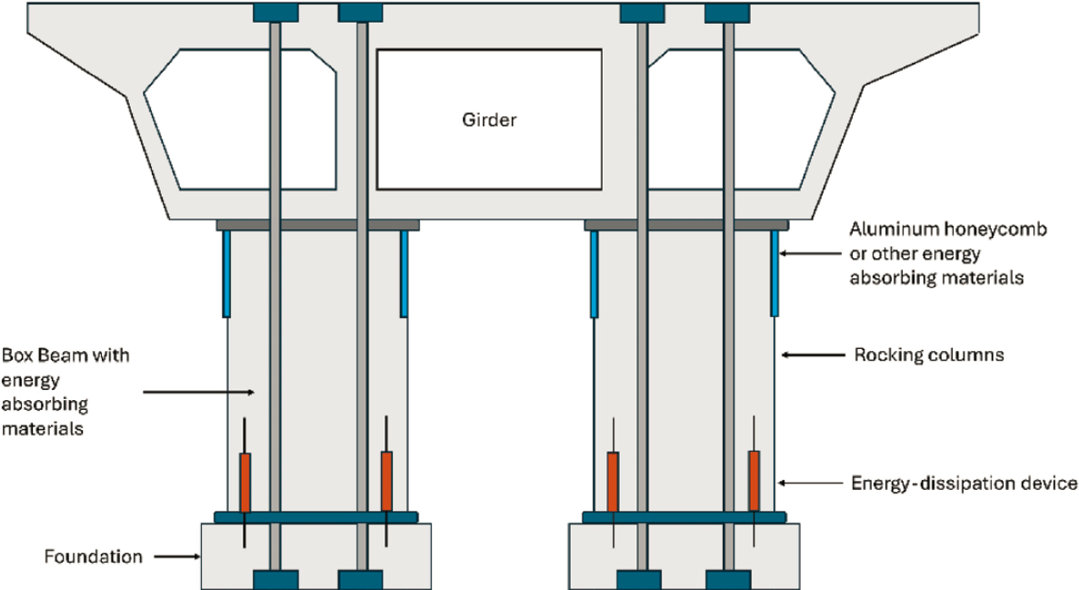
Where to Use
Energy-dissipative systems are typically located on the bottom portion of exterior girders of bridges. This includes energy-absorbing materials such as aluminum honeycomb. For limited access facilities, this type of treatment would generally apply to the first bridge in the series from each entry point.
Safety Effectiveness
An energy-dissipative system acts as a reactive sacrificial system in the case of BrTS to mitigate the damage to both the bridge and commercial vehicle. This countermeasure is in the prototype and development phase.
Costs and Service Life
The system may need to be replaced after each BrTS incident, so service life depends on the number of BrTS occurring post-installation. Costs vary as the prototype is under construction. Depending on the features desired and areas covered, there may be multiple vendors that can meet an agency’s needs. Agencies are encouraged to conduct due diligence in evaluating the options available.
Active Systems
The purpose of these countermeasures is to improve driver awareness of bridges and tunnels through detection- or location-based warning systems. The following countermeasures are categorized as active systems:
- Routing systems.
- Early warning detection systems.
- Smart Roadside commercial motor vehicle monitoring.
- License plate camera recognition system.
- Structure monitoring systems.
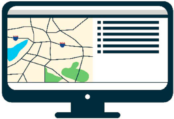
Routing Systems
Description
Routing systems for oversize vehicles are designed to improve safety and protect infrastructure. Agencies often use these systems to issue permits more efficiently and to ensure an accurate and reliable route (Figure 36).
Where to Use
Routing systems are used when planning a route and issuing a permit.
Agencies can consider the following factors when assessing the potential use of routing systems:
- Features desired.
- Maintenance of underlining data.
- Technical support.
- Data storage.
- Expandability.
- Interface and communication features.
- Security of input data/hauler information.
- Virus protection.
- Cost.
Safety Effectiveness
Accurate routing systems can minimize human error in route planning, thereby improving the efficiency and effectiveness of this countermeasure. Accurate and reliable routing and permit issuance may be the single most effective countermeasure to mitigate BrTS, assuming the hauler follows the approved route.
Enhancements
Haulers may have difficulty understanding information or restrictions from the different systems used by different authorities. Standardization, such as the following, would be valuable:
- Standardize the routing system used by all jurisdictions within a state.
- Standardize the routing system used by all states.
Costs and Service Life
Costs vary by software provider and the features included with OHVs being just one area. The software needs to be maintained and kept current with restrictions that develop or are eliminated. Depending on the features desired and the area covered, there may be multiple vendors that can meet an agency’s needs. Conduct due diligence in evaluating the options available.
Early Warning Detection Systems
Description
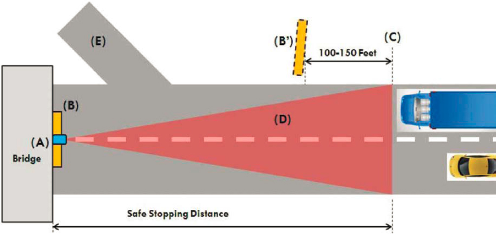
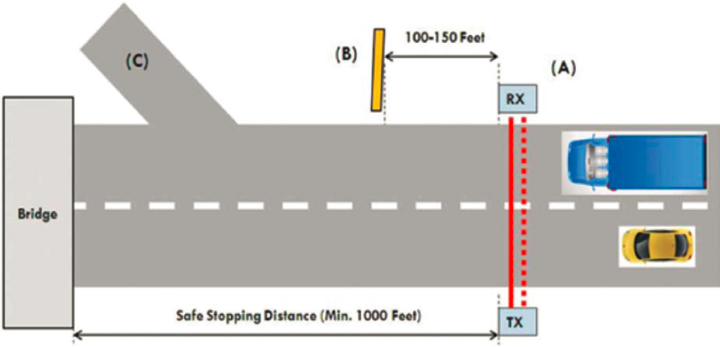
Early warning detection systems or OHVD systems are often installed upstream of low-clearance bridge or tunnel structures (a vertical clearance of 14.5 feet or less at the lowest point) at a sufficient distance for heavy vehicles to stop or exit the road before collision with the structure (Figure 37). Most systems consist of a transmitter on one side of the road (e.g., laser, infrared lights) and a receiver on the other; between these two elements, a beam of light or similar spans the roadway at a specified height and relays a notification to a connected system if the beam is broken by an OHV passing through it. The systems may also trigger video recordings of the incident or notify emergency response personnel. Driver feedback occurs immediately, and associated warning signs, beacons, or otherwise provide real-time notifications that encourage the driver to stop. The warning sign may flash yellow beacons and may or may not include an alarm (parabolic shielded bell, electronic siren, horn, etc.) to alert the driver. Variable message signs may also be used to instruct the driver to stop on the side or take some exit prior to reaching the structure. These systems typically can detect speeds up to 75 mph and are typically installed 1,000 feet before the structure to provide sufficient stopping distances. This type of system is already in use in the United States, UK, Germany, Australia, and Canada. Some systems use other light sources such as visible, red, or infrared light as well as modulation schemes to provide improved performance. Additionally, one OHVD system usually covers multiple traffic lanes
and can utilize dual beams to provide improved direction discernibility, system redundancy, and reduced false alarms. Further discussion on individual technologies for these systems is provided below.
Where to Use
Early warning detection systems vary significantly by manufacturer. These systems are reactive and may produce false positives under adverse weather conditions depending on the measurement device used. False positives, especially if they occur frequently, may cause drivers to ignore warning devices. Agencies should consider the following factors when assessing the potential use of early warning detection systems:
- Adverse weather: High winds and other severe weather may cause false positives in the system. Consider a system designed for weather conditions specific to the region.
- Ambient light: Some systems can reject ambient light, which reduces false positives and improves system performance.
- Animals: Consider the surrounding environment, as birds and other small animals may cause false positives.
- Power: These systems require a constant power source, which may vary by manufacturer.
Safety Effectiveness
Active warning systems are estimated to be 50% to 80% effective in reducing BrTS incidents (Cawley 2002). Maintenance for early warning detection systems may differ from passive systems, such as more frequent repairs and more frequent inspection as well as having more vulnerable systems components. From a human factors perspective, the danger of an active system failure could also be more detrimental compared to a passive system since failures may not be salient to road users. For example, if drivers rely on active early warning detection systems as the last defense in preventing a BrTS, a lack of indication from such a system may signal to the driver that there is no danger of collision with the structure, when in fact a failure has occurred. The
frequency of inspections and preventive maintenance may need to take into consideration these factors; regular inspections for functionality will be critical, and any components found to be nonfunctioning may need to be placarded inoperative in some way so that drivers are aware the unit or system is not currently reliable.
Enhancements
Digital signs (CMS or similar) and flashing beacons may provide real-time notifications for OHVs as they approach a low-clearance structure. These may be programmed to relay a constant warning message if the measurement system is not functional or is offline and may also alert authorities of a power failure.
Pull-over areas provided directly upstream of the structure allow OHVs to wait outside of the travel lanes for rerouting instructions or a police escort.
Like many strategies, this relies on the driver to properly interpret the message and take corrective action as appropriate or as instructed. One opportunity to enhance the effectiveness of this strategy is to be as direct and instructive as possible with any required actions. For instance, rather than stating “overheight vehicles must turn,” a message could state “overheight, turn right at pull-off.”
Costs and Service Life
The cost, service life, and functionality of these systems vary by manufacturer. Costs reported in 2011 across eight states ranged from $150,000 to $200,000 per installation (Agrawal, Xu, and Chen 2011). Note there are also maintenance (e.g., changing sensors) and operations (e.g., utility) costs associated with these systems, which are typically greater than passive systems.
More Information
North Carolina DOT installed a laser-based detection system for OHVs in Durham, North Carolina, for a low-clearance bridge that provides a grade-separated railroad crossing in a downtown area. The detection system is coordinated with flashing beacons and the traffic signal for an adjacent intersection. Notably, the signal turns red upon detecting an OHV and subsequently reduces collision speeds when collisions occur. Further, there is a dynamic sign indicating “Overheight Must Turn” (John A. Volpe NTSC 2018, 37). (Note: This example illustrates an application of an advanced warning detection system and is not meant to serve as an example of MUTCD-compliant warning signs.)
The City of Sydney, Australia, installed a unique tunnel warning system for the Sydney Harbor Tunnel, which serves roughly 100,000 vehicles per day. When the system detects OHVs approaching the tunnel, it triggers a “curtain” of water falling across the tunnel entrance onto which a giant STOP sign is projected as a pseudo-holographic image (Laservision, n.d.).
Light detection and ranging (LiDAR).
LiDAR sensors are potentially able to be installed on bridge faces above the posted clearance height pointing toward oncoming traffic. LiDAR sensors can be positioned in the middle of the traffic lane and transmit a thin triangular sheet of light toward the road surface to form an invisible light barrier across the road (Figure 38). The sensor processes any reflected laser pulses from oncoming vehicles and can activate warning messages before an OHV passes underneath a low-clearance bridge. This product also has potential uses for bridges over water to detect ships that may be overheight.
Infrared.
Most installed OHVD systems operate similarly with an optical transmitter and receiver unit using a light transmission beam (Figure 39). These optoelectronic sensors utilize different light sources to function, including infrared. While infrared sources present a moderate cost compared to camera-based systems, they have limitations, including being highly susceptible to false alarms for any number of reasons, including lost alignment between transmitter
and receiver, fog, vehicle antennas, flying debris and birds, or ice or snow formations. These costs can increase when considering installation costs including the cost of roadway closures and associated structural and electrical installation costs.
Radar.
Some radar applications exist for early warning detection systems. For example, some products use two integrated narrow-angle laser transmitters to measure two consecutive overlapping speed profiles from a commercial vehicle, allowing the system to profile the vehicle’s height, among other information. Systems built in Australia have been known to trigger false alarms if any object or debris becomes airborne and crosses the radar beam.
Camera.
Some systems may use a single calibrated or multiple video camera system to gauge and prevent OHV strikes through an early warning detection system. This typically features a camera mounted on the side of the road at the height of the low-clearance bridge or object. Camera angle calibration is determined using a reference object and may allow other features of the roadway or vehicle to be captured in the event of or in preventing a strike, such as the height of the vehicle, number plate of the vehicle, and a record of the vehicle at the scene. Cameras face certain limitations in inclement weather, including rain or fog or at night (if OS/OW vehicles are allowed to operate within that state or municipality at night), and lighting around the bridge must be adequate. A camera-based solution may be cheaper than a laser or infrared light warning system or transmitter. Efforts to introduce camera-based systems have been undertaken, including in Cambridge, England.
Smart Roadside Commercial Motor Vehicle Monitoring
Description
Smart roadside commercial motor vehicle monitoring systems feature a variety of technologies that enable the scanning of commercial vehicles (Figure 40). Smart roadside systems measure and record a vehicle’s height, length, and width; can photograph and scan a vehicle’s license plate; potentially produce a three-dimensional (3D) model of the vehicle; scan and record the vehicle’s axle count, spacings, and potential load; determine the vehicle type and classification; and verify the vehicle against a valid issue permit for accuracy and compliance. Different vendors may include some or all of these features and are generally able to record this information while the commercial vehicle is in motion. Technologies incorporated into these monitoring systems may include LiDAR scanners, cameras, and cloud databases. Eye-safe cameras or other sensors (including LiDAR or infrared) that can scan an object—in this case, a commercial motor vehicle—multiple times per second, enabling fully automated length, width, and height measurement with the vehicle speed and movement direction. Software suites may also include the ability

to display movements in real-time and store information in a local database through a cloud-based system.
Where to Use
Agencies should consider the following factors when assessing the potential use of connected vehicle technologies:
- Reliability of broadcast signals.
- Costs to install and maintain broadcasts.
- Cybersecurity and privacy concerns associated with connected vehicle information.
- Liability.
Safety Effectiveness
These systems focus on the enforcement of high-risk carriers. Automated vehicle attribution can improve precision and reduce human error, thereby increasing road safety while preserving infrastructure integrity. This offers a proactive safety measure to check a commercial motor vehicle’s height and weight and potentially alert the driver in case of routing noncompliance or an unexpected hazard in the path of travel.
Enhancements
Enhancements may include software suite enhancements, such as the ability to produce a 3D model of the vehicle, or infrastructure enhancements, such as the use of multiple cameras to gauge a vehicle’s weight while in motion.
Costs and Service Life
The service life of the key ITS technologies—including camera/sensor systems (LiDAR/Infrared)—is the main limiting factor. Service life for these technologies varies widely. LiDAR systems can have an expected warranty of only 2 years at a minimum. As these technologies are integrated; if one system fails, the whole system may become nonfunctional. A single, automated vehicle dimensions measurement laser sensor may cost $1,600 to $2,000 per unit; however, many of these units may be necessary to complete a smart roadside commercial motor vehicle monitoring system.
More Information
Illinois DOT is utilizing a pilot project to explore this technology at the Maryville weigh station on I-70 using 31 cameras to measure freight loads as they approach the scale and compare to permit details.
License Plate Camera Recognition System
Description
Also known as an automated license plate reader (ALPR), a license plate camera recognition system can record a vehicle that has struck a bridge. ALPR technology utilizes cameras and alphanumerical recognition software to read license plates as they pass (Figure 41). ALPR technology has been used primarily for law enforcement purposes by police throughout the United States.
Where to Use
Generally, license plate camera recognition systems are permanently mounted to infrastructure, including bridges and light poles, or fixed to infrastructure components near bridges and other key infrastructure points. When purchasing ALPRs, agencies will need to determine the potential future ancillary purposes of license plate camera recognition systems—such as to complete traffic studies or implement tolling—and address data privacy concerns and data storage and retention processes.

Safety Effectiveness
ALPRs are primarily used for enforcement and compliance with registration, vehicle size, vehicle weight, and operational requirements. These cameras allow an agency to monitor damage caused by heavy vehicles on roadways and ensure commercial motor vehicle compliance. Technical challenges include accuracy and reliability issues with both equipment and databases, especially on older models of equipment, and maintenance. Most use of ALPRs is reactive (Zmud et al. 2021).
Costs and Service Life
The cost of a single ALPR camera can be up to $20,000, not including installation, fiber optics, and other soft costs (Eberline 2008).
More Information
More widespread use of license plate camera recognition systems includes the ability to monitor traffic flow, flag unpaid license and registration vehicles, monitor insurance compliance, and explore other transportation policies/solutions, such as congestion charges, tolls, and high-occupancy travel lanes.
Structure Monitoring Systems
Description
Structure monitoring systems, as illustrated in Figure 42, continuously monitor infrastructure and infrastructure health, including bridges and tunnels. Advanced structural monitoring methods allow for the early detection of possible structural deterioration with the goal of extending the lifespan of structures. These systems monitor the structure and are capable of recording strike incidents and transmitting warning messages to authorities to inspect, or if needed, shut

down the facility. This can be done through a wireless sensor network form that combines a large number of sensor nodes in the monitoring area into a network system, generally through wireless communication technology.
Where to Use
Structure monitoring systems are typically installed in key areas underneath or on top of bridges. They utilize a variety of sensors including
- Strain gauges,
- Strain meters,
- Inclinometers,
- Crack and joint sensors,
- Tilt sensors, and
- A variety of accelerometers.
These systems may monitor the foundation and super- or substructures of bridges.
Safety Effectiveness
These systems allow agencies to immediately detect a structure impact or collision and determine if crews are needed on-site to survey the damage. Structure monitoring systems that continuously monitor a piece of infrastructure may also reduce the likelihood of premature or unexpected damage or events and provide inspectors with a plethora of historical data on bridge and tunnel performance (Deng et al. 2023).
Enhancements
Some structure monitoring systems may include options for building information management, digital twinning, or utilizing artificial intelligence for structures. Some systems provide a variety of structural health monitoring including using nondestructive testing technologies, remote online monitoring, seismic monitoring, and beam-fatigue analysis.
Costs and Service Life
Structure monitoring systems can assist agencies in prolonging the deterioration and preserving the state of good repair of structures, which can have an expected service life of 100 years. Costs of sensors associated with structure monitoring systems vary from hundreds of dollars up to thousands of dollars per unit, while the number of units varies for the intended purpose (up to hundreds of strain gauge sensors may be necessary to create an adequate structure monitoring system) (Dalia et al. 2018).
Vehicle-Based Systems
The purpose of these countermeasures is to improve driver awareness of bridges and tunnels through technology and in-vehicle systems. The following countermeasures are categorized as vehicle-based systems:
- In-cab technology.
- Connected vehicle technologies.
- Subscription service.
- Raised dump body light-and-sound warning system.
- Truck-mounted systems to monitor vehicle load.
In-Cab Technology
Description
Dating back to 1945, CB radio provides short-range communication services and real-time traffic and emergency updates for truckers across the country. Most CB radios and base station
transmitters have a broadcast range of up to 15 miles. Jurisdictions can install broadcast stations in the vicinity of low-clearance bridge or tunnel structures (those with a vertical clearance of 14.5 feet or less at the lowest point) to periodically send automated, recorded messages to drivers with their radios turned on while in range of the broadcast station to warn them of the structure ahead.
Where to Use
Agencies can consider the following factors when assessing the potential use of CB radio warning systems:
- Cell phone service: CB radios are particularly useful where gaps in cell phone coverage persist, such as in rural areas. CB radios may be the only method of communication available to drivers on parts or all of their routes.
- Broadcast station: Collaborate with local broadcast stations to determine appropriate CB radio stations for broadcasting low-clearance information. CB radios can use up to 40 discrete channels, but professional truckers commonly use only 2 or 3, and selection depends on the given route.
- Area: CB radios are not recommended in urban areas as the broadcast distance could capture many truckers on unrelated routes, which may decrease the effectiveness of messaging as drivers learn to ignore the warnings.
Safety Effectiveness
Research is not yet available for the safety effectiveness of in-cab technology as a BrTS countermeasure.
Enhancements
Multiple sources of messaging are recommended to capture as many drivers as possible. While commercial drivers still commonly use CB radios, pushing alerts through other media, such as mobile applications, may capture more of the large-vehicle driving population.
Costs and Service Life
One source suggests an average cost of $300 per CB radio transmitter (Cawley 2002). Service life estimates vary depending on maintenance and manufacturer.
Connected Vehicle Technologies
Description
Using signal towers or compact roadside units along the highway, individual trucks receive real-time updates about weather, road conditions, and road work, including clearance warnings (Figure 43). The system should provide enough advanced warning for drivers to reroute or stop before hitting a structure.
Where to Use
Agencies should consider the following factors when assessing the potential use of connected vehicle technologies:
- Reliability of broadcast signals.
- Costs to install and maintain broadcasts.
- Cybersecurity and privacy concerns associated with connected vehicle information.
- Liability.
Safety Effectiveness
Connected vehicles can reduce the costs associated with BrTS. Roadside units are effective when there is a corresponding unit in the vehicle cab to receive the signal. Other systems that
broadcast information widely to apps or specialty devices may also be effective. While it is generally accepted that connected vehicle technologies can mitigate BrTS by providing drivers with warnings about potential hazards, the effectiveness has yet to be quantified.
Enhancements
There appears to be a need for transportation agencies or infrastructure operators to communicate appropriate freight- and trucking-related road network information that may influence driver assistance systems (e.g., changes to road geometry, bridge clearances, temporary traffic diversions, electrical charging stations). These upgrades are part of a larger set of options.
Agencies could also use roadside units to collect BrTS data (e.g., number of impacts or preliminary damage assessments).
Costs and Service Life
Roadside units cost approximately $500 although costs vary. To receive the broadcast, each truck needs a receiver.
More Information
FHWA’s Connected Vehicle Pilot program deployment in New York City provided eight roadside units to broadcast bridge clearance information and other details. This application was deployed in limited conditions during the pilot (HDR, n.d.).
Subscription Service
Note: Several subscription-based service companies offer safety alerts for low bridges. At the time of this guide, products on the market that offer in-cab, low-bridge warnings include but are not limited to Drivewyze, GreenRoad, Sentinel, High-Tech Sign, Garmin, and EXEROS Technologies.
Description
A subscription-based service uses a mobile application to communicate messages to commercial drivers. As shown in Figure 44, these messages can include safety notifications regarding rollover zones, low bridges, steep grades, runaway ramps, brake-check areas, weight restrictions, work zones, high collisions, and more.
Some services can collect driver safety information from a variety of sources. Agencies can coordinate with providers and their partners to disseminate safety and restrictive notifications as needed, such as when a major storm is approaching. Some services also partner with major data collection agencies to provide real-time notifications regarding traffic congestion, work zone presence, and a variety of other safety-related travel measures.
Commercial drivers actively using these services can receive push notifications to their mobile device when they are within a geofenced area that has an alert set up, such as for a low bridge. The geofence is large enough to provide the driver adequate time to make decisions before reaching the low bridge. The service provides low-structure alerts for clearance heights (e.g., 14.5 feet or lower).
Where to Use
Consult with service providers to ensure coverage is available in your area.
Safety Effectiveness
Research is not yet available for these services as a BrTS countermeasure.
Enhancements
Some services provide additional information such as infrastructure (parking, rest stops, etc.) and other notifications (weather alerts) as part of a paid subscription. Consult service representatives for more information.
Costs and Service Life
Subscription-based services typically operate as a monthly subscription service. At the time of this publication, the cost for some basic packages was under $20 per month and included safety notifications for low-clearance structures. Low-clearance bridges and tunnels are typically defined as having a vertical clearance of 14.5 feet or less at the lowest point, but this may vary by the service provider. Service life is indefinite, depending on the company’s continuation of services.
Raised Dump Body Light-and-Sound Warning System
Description
Dump body safety devices warn heavy dump truck drivers when there is a problem with their dumper (Figure 45). A dump body is a metallic body whose upper part is generally open and intended for transporting bulk materials. This safety equipment uses both an audible warning device and a warning light to let the driver know when the bucket is still raised while the truck is moving. When a dump body is raised, this can exceed the normal traveling height of the vehicle and may result in a bridge or overhead object collision.
Where to Use
Most dump body safety devices feature a light-up display and audible warning device located within the cab of the truck. Certain models may not activate until the truck reaches a certain speed and are meant for vehicles that move at reduced speeds during unloading to limit inconveniences for the driver.
Safety Effectiveness
These systems act as a preventive safety measure on specific types of commercial vehicles only.
Enhancements
Some models include options for limiting that alarm at low speeds, other speed adjustments, and additional warning inputs. Vendor models vary including different intensities of alarm noise, light flashing frequency, and outside temperatures that the raised dump body systems can withstand. There is an opportunity to consider national vehicle standards for raised dump body warnings.
Costs and Service Life
While exact service life may vary, many vendors supply models with a 2-year warranty. The unit costs around $100, not including installation costs and maintenance.
Truck-Mounted Systems to Monitor Vehicle Load
Description
Truck load monitoring systems may monitor information on a commercial vehicle, including the total vehicle load or axle load or the vehicle’s height (Figure 46) and any changes to the load.
Where to Use
While sensor components of this system must be mounted on the vehicle, such as on the vehicle’s body, trailer, or on top of a truck, these systems generally include an in-cab warning system to alert the driver about shifting vehicle loads or low-clearance hazards.
Safety Effectiveness
Some models may include an aerodynamic sealed sensor unit capable of measuring the height of an overhead hazard and sending a read-out to the in-cab unit to alert the driver. Others may include a dash video insert that will measure and detect the height of the vehicle even as the load changes. Some systems are geofenced and may only operate in certain states based on integrated bridge and other low-height clearance restriction data. Most systems generally include an audible alarm to alert the driver to any excess axle load or low-clearance hazard. Some modern systems may use two cameras together to increase depth perception.
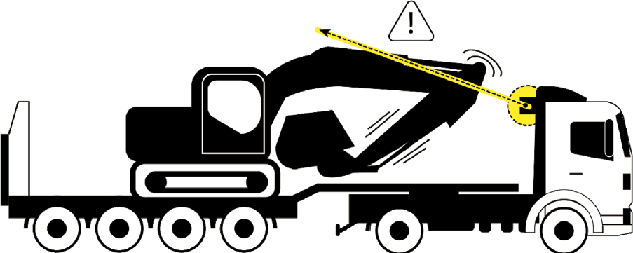
Enhancements
Certain truck-mounted, vehicle load monitoring systems may include a telematics unit or GPS tracker to communicate information to an online fleet management software or the driver’s smartphone.
Costs and Service Life
Camera-based technology with a software suite generally costs from around $500 to $1,000 and may more, depending on installation costs (Maghiar, Jackson, and Maldonado 2017).
Nonphysical Countermeasures
The purpose of these countermeasures is to improve driver awareness of bridges and tunnels through institutional policies, permitting procedures, and driver education programs. The following countermeasures are categorized as nonphysical countermeasures:
- OHV and axle load restrictions.
- OHV permits.
- Vehicle checklists.
- In-cab height placard.
- Route surveys.
- Pilot car/escort vehicle policies.
- Route atlas (Motor Carriers’ Road Atlas, Truckers Atlas).
- Commercial navigation system policies.
- Training and CDL certification.
- Post-training/certification driver education and outreach programs.
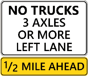
OHV and Axle Load Restrictions
Description
There are several options for posting signs to restrict vehicles. A “Passenger Vehicles Only” sign restricts any commercial vehicles, including delivery or single-unit trucks. “No Truck” regulatory signs are posted at the beginning of the ramps that lead into the roadway section (Figure 47). Axle load restrictions generally refer to weight limits based on distance between axles for bridge formula calculations. Axle spacing is typically measured from the center of the axle to the center of the axle between the outermost wheel or group of wheels.
Where to Use
Agencies can consider the following factors when assessing the potential use of OHV and axle load restrictions:
- Limited commercial businesses on that corridor.
- Operational efficiency or congestion relief.
- Load rating of structures in the corridor.
- Pavement construction and design.
Unintended consequences can include increased truck traffic on parallel or adjacent roads and difficultly for trucks and delivery vehicles to access certain businesses and destinations.
Safety Effectiveness
Truck restrictions can mitigate BrTS by limiting the size and weight of trucks allowed on certain roads and bridges. This can help deter trucks that are too tall or too heavy to safely pass under or over bridges and tunnels. The effectiveness is dependent on driver compliance, which may require supplemental enforcement. There is limited research on the safety effectiveness of vehicle restrictions. Truck lane restrictions can reduce the number of rear-end collisions involving trucks in mixed traffic settings. Truck lane restrictions and vehicle restrictions along certain corridors can also improve traffic flow.
Enhancements
Periods of increased enforcement may be necessary to deter trucks on a posted corridor. In addition, education and outreach are appropriate if there are changes to the allowed traffic on a corridor.
Costs and Service Life
The total cost of posting a truck restriction on a highway will vary depending on the length of the highway segment, the type of restriction implemented, and the level of enforcement. Enforcement and monitoring may be necessary, which can increase the cost associated with signing alone. Costs of truck restrictions can be significant to motor carriers (e.g., increased travel time, routing decisions, hours of service, potential litigation). Agencies should consider all costs before implementing such a restriction.
More Information
For more information on truck lane restrictions, agencies can refer to individual state statutes. There are multiple restrictions on the use of policy to restrict traffic.
OHV Permits
Description
A permit authorizes the movement of an OS/OW vehicle for a specific time period on permissible hauling days. An authority (e.g., state, city, county, town, village) may require a permit for vehicles or loads that exceed legal dimensions in their laws (Figure 48). Applications are required and the permit issued will identify restrictions and an approved route.
Where to Use
Agencies may consider the following factors when assessing the current or potential use of policies and procedures for OHV permits:
- Simple and timely application process.
- Resources and tools needed to issue permits.
- Application and permit fees.
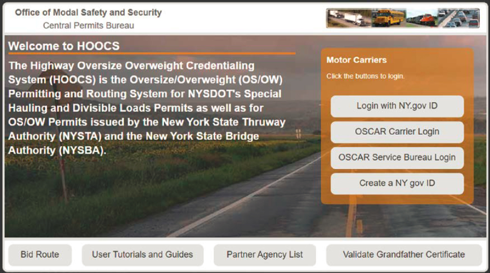
-
Information necessary to issue a permit, such as
- Applicant/company/carrier contact information,
- Current insurance coverage,
- Vehicle information,
- Load information, and
- Trip information.
- Quality assurance process and accuracy of information.
- Communication methods with applicants (e.g., online, email, phone).
Safety Effectiveness
Accurate and reliable routing and permit issuance may be the single most effective countermeasure to mitigate BrTS, assuming the hauler follows the approved route.
Enhancements
Haulers may have difficulty understanding information or restrictions from the different systems used by different authorities to issue a permit for a single trip. The following are opportunities to enhance the effectiveness of the permitting process:
- Standardize the permitting process across jurisdictions (one-stop shopping). Note that AASHTO developed a recommended standardized permit form to encourage harmonization of permit information as documented in Permit Data Harmonization Model Permit & Best Practices (Athney Creek Consultants 2022).
- Improve coordination and data sharing of permits across states.
- Automate permit issuance systems in those jurisdictions with a manual process.
Costs and Service Life
The cost varies by jurisdiction and depends on whether a single-use, monthly, or annual permit is requested. Price may also vary by route distance. The permit issued will specify the time constraints (e.g., good for 5 weekdays from 30 minutes after sunrise to 30 minutes before sunset).
Table 13 is an example of state permit fees (NYSDOT 2023).
Table 13. Example of state permit fees.
| Trip | Fee |
|---|---|
| Single trip | $40 |
| Monthly – 100-mile radius | $60 |
| Special vehicle combination | $100 |
| Annual – 100-miles | $360 |
| Special vehicle combination | $500 |
More Information
Most states, cities, counties, towns, and authorities have a permit policy and procedure in place. Information is typically available through the jurisdiction’s website, and most are processed online.
Vehicle Checklists
Description
Checklists increase driver awareness of vehicle constraints, cargo securements, and driver preparedness. Checklists can be created for pre-, mid-, and post-trip completion. Checklists should include measuring the height and width of trucks as well as engine and cab inspection. Figure 49 and Figure 50 show examples of vehicle checklists.
Where to Use
Agencies should consider the following factors when assessing the potential use of vehicle checklists:
- Height measurement training: Drivers often incorrectly measure vehicle and cargo heights, so relevant and ongoing training is critical for reducing BrTS incidents.
- Cargo inspection: Cargo can shift during transit, and drivers should be aware of and react to possible changes in their maximum load height throughout the trip.
- Complacency: As with any repetitive task, drivers may become less attentive over time to standardized checklists. Checklists should be kept to a manageable length to reduce the potential for complacency.
Safety Effectiveness
Research is not yet available on the safety effectiveness of vehicle checklists as a BrTS countermeasure.
Enhancements
Agencies can consider the following enhancements for vehicle checklists:
- Update in-cab height placards at the start of each trip.
- Require drivers to report their maximum load height and other key checklist items to the managing organization before a trip commences.
- Provide drivers with instructions and tools or equipment to measure load height more accurately (e.g., technologies to create a 3D model of the truck) to reduce common mistakes in measuring load height.
Costs and Service Life
Vehicle checklists can be developed by an individual or managing organization with minimal labor hours. Personnel executing the checklists must spend time before, during, and/or after the trip on the task, which may impact trip scheduling and hours of service.
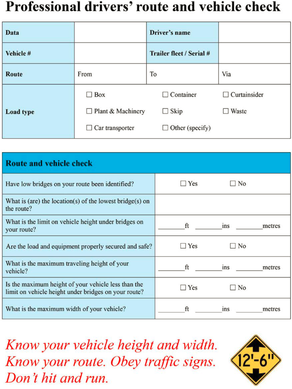
Service life is variable; checklists can be continually updated as the vehicle fleet, driver needs, and cargo makeup change, or due to anything that may impact the serviceability of vehicles, safety of driving personnel, or safety of other roadway users.
In-Cab Height Placard
Description
An in-cab height placard is an adjustable message board that displays the total height of the truck for referencing at low-clearance warning signs. This is especially beneficial when the driver is unfamiliar with the vehicle, such as with box truck rentals or for commercial drivers with inconsistent vehicle/cargo assignments. An in-cab height placard can be as simple as a piece of paper with the total height of the vehicle/cargo written on it. As long as it is within the field of view of the driver (in a way that does not obstruct their view of the road), drivers will not have to memorize the height and can reference it as needed when they see low-clearance warning signs.
Where to Use
Commercial motor carriers, box truck rental companies, RV rental and sales companies, and any other large-vehicle distributors and drivers can benefit from using in-cab height placards. Vehicle height must be accurately measured and confirmed each time any changes are made to the cargo or vehicle. Height measurements may require special tools or training depending on the vehicle/load configuration.
Safety Effectiveness
Research is not yet available for applications of in-cab height placards as BrTS countermeasures.
Enhancements
None applicable at this time for this system.
Costs and Service Life
Material costs and service life are generally negligible for this countermeasure. Height placards should be updated any time modifications are made to cargo or vehicles.
Route Surveys
Description
A common requirement for permitting oversize vehicles is the completion of a route survey. Route surveyors are trained to drive with specific constraints in mind related to the intended transport. They can identify low-clearance bridges (a vertical clearance of 14.5 feet or less at the lowest point), narrow roadways, railroad crossings, low-hanging electrical wires, overhead obstructions, difficult road geometry, and other impediments that may obstruct the intended route based on the load and vehicle characteristics. Route surveyors often use a height pole attached to the vehicle to verify vertical clearance at bridge and tunnel structures. Route surveyors also work with the trucking company and local authorities to identify alternative viable routes where needed. Performing a route survey identifies problems before the route commences, improving the chances for a successful trip and directly reducing the likelihood of BrTS incidents.
Where to Use
Route surveys are commonly required by law for oversize vehicles, but they are also beneficial for any heavy vehicles driving on public roads. Some commercial motor carriers perform route surveys before establishing a new, repetitive route.
Safety Effectiveness
Safety is prioritized over the shortest route, so selected routes may involve increased distances and roads with lower operating speeds. Research is not yet available for the safety effectiveness of route surveys as BrTS countermeasures.
Enhancements
Technology, such as dashboard cameras and voice recorders, may improve route surveys.
Costs and Service Life
There is a fixed cost associated with training the route surveyor. Variable costs include the time and fuel to complete the task. The variable costs will depend on the length of the route and the time to complete the survey. Route surveys should be performed close to the commencement of the trip and updated periodically; communicating with local jurisdictions can help identify work zones, pavement overlays, and any other planned changes along the identified route.
More Information
Pilot/Escort Vehicle Operators: Training Manual (Hamilton 2017).
Pilot Car/Escort Vehicle Policies
Description
Oversized vehicles are commonly required to travel with a leading and/or trailing pilot car/escort vehicle operator (P/EVO) (Figure 51). P/EVOs are used to warn road users of a potential oncoming hazard and to guide large vehicles through or around downstream obstacles that may impede travel. P/EVOs are commonly outfitted with signs, flags, warning lights, and other equipment depending on the governing agency. High visibility is critical for a successful transport. Through constant communication with the driver of an oversize vehicle, P/EVOs can help with stopping and turning maneuvers and communicate downstream travel constraints via CB radio or otherwise.
Where to Use
In many states, oversize vehicles are unable to travel on public roads without an accompanying P/EVO. Laws vary regarding the number of P/EVOs required and minimum thresholds (e.g., vehicle and cargo dimensions and gross weight) that trigger the need for a P/EVO. Many states require cross-coordination among several agencies for a successful oversize-vehicle permit and transport process.
Safety Effectiveness
Research is not yet directly available for applications of P/EVOs as BrTS countermeasures.
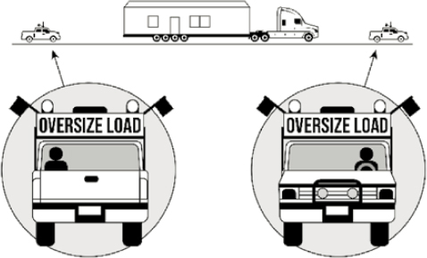
Enhancements
Defensive driving courses can improve P/EVO training programs. While P/EVO training courses already exist, they are not required in all states. One opportunity is to require this training and certification in all states with a mandatory refresher every 3 years to remain certified. Another opportunity is to require the use of commercial navigation systems for P/EVO certification (refer to Commercial Navigation System Policies section for further discussion on commercial navigation systems). Vehicle selection for both P/EVOs and heavy vehicles is also increasingly important as new suites of sensors for collision mitigation become available, including side view assist, forward collision warning/mitigation, lane departure warning/mitigation, and electronic stability control, among others.
Costs and Service Life
There are fixed costs and variable costs associated with P/EVOs. P/EVOs are generally required to be trained and/or certified for the task, so there is a fixed cost associated with their training. Some jurisdictions require state-specific vehicle permits; amber light permits; and/or insurance in the form of automotive liability, general liability, and/or professional errors and emissions policies. The variable costs include the time and fuel to complete the task at hand. The variable costs will depend on the length of the route and the time to complete the trip.
More Information
Pilot/Escort Vehicle Operators: Best Practices Guidelines (Hamilton and Owens 2017).
Road Atlas
Description
A road atlas displays low-clearance bridges (a vertical clearance of 14.5 feet or less at the lowest point) on any highway or local road for drivers to reference (Figure 52). Drivers can use a road atlas in conjunction with other navigation software.

Where to Use
An atlas should not be used while driving. Drivers and carriers can use an atlas when
- Engaged in planning and selecting a route,
- Stopped en route to verify or confirm a route, and
- Diverted from a route for emergencies resulting in road closures or diversions or for any other reason.
An atlas is also useful in areas with no cellular or internet service.
Safety Effectiveness
Lack of route planning by haulers has been determined to be one of the leading causes of BrTS (Agrawal, Xu, and Chen 2011; Martin and Mitchel 2004). An atlas is a cost-effective tool to plan routes, particularly for small or occasional carriers.
Enhancements
Atlas publishers could offer digital updates on a regular basis to atlas purchasers.
Costs and Service Life
Atlases are available for purchase online from retailers and publishers as well as in bookstores. They range in price from $15 to $60. While atlases are updated annually, older atlases will include most low-clearance bridges, as low-clearance bridges tend to be older.
More Information
An online atlas is more likely to be current. A printed atlas may not have the most current information and should be used in conjunction with other countermeasures.
Commercial Navigation System Policies
Description
GPS-based navigation systems used by the general driving population do not provide low-clearance warning notifications for bridge or tunnel structures. Commercial navigation applications have this information built in, and they can be programmed to automatically avoid problematic routes and provide audible warnings when approaching low-clearance structures. These specialized commercial navigation applications may reduce BrTS incidents when their use is encouraged and/or required and enforced by motor carriers, law enforcement, and policymakers.
Where to Use
Agencies may consider the following factors when assessing the potential use of commercial navigation system policies:
- Functionality: Key functionality of commercial navigation systems includes GPS-based (not cellular), regular and free software updates, visual and audible warnings, large screen size, customizable based on vehicle height, mounting options, lane assist, and turn-by-turn guidance.
- Source of vertical clearance information: The reliability of these systems is often dependent on the timeliness and accuracy of data from transportation agencies. There is a need for transportation agencies to maintain and provide access to a timely and reliable database of low-clearance structures that is integrable with major commercial navigation.
- Collaboration with manufacturers: Ensuring the devices are gathering information from the correct sources will improve the effectiveness of commercial navigation system policies. There is also a need for the manufacturers to push updates to the devices and for drivers to check for updates regularly to confirm the system is relaying the most recent information.
Safety Effectiveness
NYSDOT estimated that more than 90% of truck drivers were following automobile GPS guidance (i.e., not using a commercial navigation system with horizontal and vertical clearance data) at the time of a bridge strike on parkways (Agrawal, Xu, and Chen 2011).
Enhancements
Some commercial navigation systems provide additional safety-related information beyond vertical clearance data. This could be required for P/EVO certification. Consult individual GPS manufacturers for more information on available services.
Beyond the provision of vertical clearance data for permanent structures, there is an opportunity for transportation agencies to post temporary or recent changes on 511 (e.g., short-term, construction-related activities that affect vertical clearance). Further, there is an opportunity for commercial navigation systems to consume and provide this data to users.
Costs and Service Life
One source suggests an average cost of $200 to $900 per device, depending on desired features, plus a possible nominal monthly fee (Elgin 2023). Service life depends on the selected manufacturer. Base data sources and navigation systems must be updated regularly to capture new information.
Training and CDL Certification
Description
CDL training and certification improve truck drivers’ knowledge about driving larger vehicles, including the associated risks and opportunities to mitigate those risks. It is estimated that a high number of crashes are caused by human factors, including failure to use safety belts, driving too fast for conditions, inadequate surveillance of the roadway environment and failure to notice potential hazards, driver fatigue, driver distraction, following too closely, and inadequate evasive action to prevent collisions.
Drivers hauling cargo can benefit from load securement training to help prevent damage to the infrastructure and cargo and understand DOT regulations. Many load securement or cargo control training offerings include aiding drivers in understanding and assessing various aspects of load securement. For example, for load securement systems involving chains, drivers should understand the working load limit or rated capacity of the chain or sling components as well as the minimum breaking force as tested and verified by the manufacturer of the chain or sling components. Training also covers other aspects of load securement, including relevant regulations, inspection intervals, required securement points based on load dimensions, and securement strategies/types of tie-downs. Common cargo securement violations include failing to secure vehicle equipment, failing to load vehicles to prevent load shifts, insufficient tie-downs, loose or unfastened tie-downs, and damage to securement systems or tie-downs.
Where to Use
This is mandatory for all commercial truck drivers.
Safety Effectiveness
Regular cargo and tie-down inspection intervals are required for compliance with regulations as well as to enhance safety. For example, it is recommended that drivers inspect their cargo before the vehicle is taken on the road, within the first 50 miles of any trip, and then at regular intervals based on whichever occurs first: every 150 miles, every 3 hours of driving, or each duty status change. Regular inspection can prevent load shift issues by allowing drivers to detect movement or shifting of a load before it becomes a safety hazard.
Enhancements
In the aviation industry, training has proven highly effective for commercial pilots. Training is done using a standardized curriculum and meeting training requirements outlined in 14 CFR Part 135 and 142. This standardization has aided in the effectiveness of training as all carriers are required to meet the same standards and provide the same training at the same frequency to all pilots. Standardized curricula are created for specific aircraft types and include applicable regulations, resources for maintaining training syllabi, differences in training types (initial hires, initial equipment, transitions, upgrades, recurrent, adaptive recurrent, or requalification) as well as recommended topics covered and sample checklists to utilize during training. This standardization would benefit motor carriers looking to improve their driver training programs and training effectiveness; it would also ensure that all motor carriers’ employees are operating with the same skill sets throughout the nation.
Costs and Service Life
Costs and training frequency requirements vary.
Post-Training/Certification Driver Education and Outreach Programs
Description
Driver education and outreach programs may benefit both professional trucking industries and nonprofessional drivers (e.g., those with passenger vehicle licenses operating rented or purchased large vehicles). Examples of education and outreach may include newsletters, seminars, coordination with driving schools, inclusion of a section related to BrTS in CDL testing, outreach with carrier organizations and independent operators, websites, annual safety courses, or any combination. Possible education or outreach programs may include the following:
- For professional truck drivers: This may include routine refresher courses on measuring vehicle and cargo height, selecting routes appropriate for their vehicle height, and ensuring commercial GPS systems with low-clearance structure warnings are used.
- For nonprofessional drivers: This may include coordination with local moving truck rental companies, RV retailers, and motor vehicle licensing offices to improve awareness of vehicle heights and roadway restrictions. Drivers may be unaware that truck prohibitions and low-clearance warnings apply to them, as formal education on this subject is often not provided upon issuance of driver licenses for passenger vehicles or when renting a vehicle.
One challenge to driver education is the diversity of the trucking industry where carriers range in size from large companies with more than 1,000 drivers to single-person owner-operators. Another challenge is bad operators (e.g., chameleon carriers that change the company name after being put out of business). It is generally difficult to change the behavior of these operators who intentionally violate rules and regulations.
Where to Use
Agencies can consider the following factors when assessing the potential use of driver education and outreach programs:
- Crash history: Consider targeting outreach and education programs to the appropriate offending driver population, based on whether BrTS incidents are occurring due to professional truck drivers or nonprofessional drivers in similarly large vehicles. Further investigation may reveal patterns in BrTS incidents to narrow the target audience for education and outreach programs, such as whether these incidents are more often related to fleet operators or independent operators.
- Trucking industry needs: Consider a collaborative approach with trucking industry leaders to establish viable truck routes and standardized procedures for avoiding low-clearance structures.
Safety Effectiveness
Research is not yet directly available for applications of post-training/certification driver education and outreach programs as BrTS countermeasures.
Enhancements
Agencies can consider the following enhancements to driver education and outreach programs:
- In-cab height placards: This may be particularly beneficial for nonprofessional drivers renting or purchasing vehicles when a formal training program is not required to operate the vehicle.
- Enforcement of truck prohibitions through fines or other techniques: This may improve adherence to truck restriction policies and subsequently reduce BrTS incidents. This may require coordination with law enforcement and policymakers in adjacent states or jurisdictions as well as tribal community representatives.
- Newsletters or similar: Photographs of bridge hits, congestion caused by bridge hits, and associated statistics may be beneficial, particularly if this information is distributed in response to permit requests.
- Consider requiring periodic (e.g., annual) refresher courses to promote continuous awareness of the associated social and economic costs of BrTS events and how to prevent them.
Costs and Service Life
Costs and service life vary depending on the agency offering certifications, frequency of staff turnover for personnel receiving training, and frequency of refresher courses.
Other Tried Strategies
In addition to the extensive list of countermeasures in the previous sections, transportation agencies and local governments have tried other strategies to prevent or mitigate BrTS. The following are select examples of these strategies:
- Lane reduction.
- Ramp closure.
- Increased fines and enforcement.
Lane Reduction
If there are multiple lanes under a bridge or in a tunnel, there is an opportunity to reduce the number of lanes. A lane reduction intends to shift the travel path of vehicles to the location where there is the greatest clearance height and avoid areas under the bridge where there is low clearance. Other benefits of lane reduction can include reduced travel speeds, increased driver awareness of warning signs, and added shoulder width for pedestrian or bicycle facilities.
Example Application: In June 2023, the NYSDOT implemented this strategy on the four-lane Route 370 (Onondaga Lake Parkway) for a distance of 1,200 feet on each side of the CSX railroad bridge, which is intended to calm traffic and give OHVs additional time to heed the warning signs and avoid the bridge. The lane restrictions are being evaluated for their effectiveness and their impact on traffic conditions.
Ramp Closure
Ramp closures could involve complete closure to all vehicles or partial closures that prohibit certain vehicles from using specific ramps. The intent is to prevent larger vehicles from accessing roads with low-clearance bridges or tunnels.
Example Application: The NYSDOT implemented this strategy by closing a I-81 northbound ramp to State Highway 370 (Onondaga Lake Parkway) to eliminate trucks from directly accessing the parkway. The ramp closure is being evaluated to assess the impact and effectiveness of the lane reduction on the parkway.
Increased Fines and Enforcement
Local governments can increase fines for unpermitted and overweight vehicles as well as increase enforcement to support local laws. This strategy does not apply to transportation agencies, only to local communities and governments.
Example Application: In combination with lane reduction and ramp closure, the Village of Liverpool, New York, in January 2024, began enforcing its expanded truck ban, first with warnings and then with hefty fines. In the summer of 2023, the village board approved an expanded ban on trucks and tractor-trailers weighing over 5 tons from traveling through the village. The ban is designed to reduce truck traffic on Onondaga Lake Parkway as a further measure to prevent tall vehicles from hitting the famously low CSX railroad bridge. The enforcement began with signs informing drivers of the ban, a 1-week grace period, and then enforcement. The four-figure fines—ranging from $1,200 to $4,700—increase based on vehicle weight. An exception is made for local deliveries. The ban was formally introduced to motor carriers by a certified letter from the village and had to be approved by Onondaga County and the towns of Salina and Clay. While truck traffic from I-81 has been reduced with the ramp closure, which prevented many strikes, trucks from Liverpool still hit the bridge.
Data Quality Improvements
The purpose of this strategy is to improve the quality (completeness, accuracy, and accessibility) of data used to inform decisions, including the OHV permitting process. For instance, without accurate data on structure size, roadway conditions, and load size, the permitting process will not provide an optimal route. In some states, these data are collected but not easily accessible by motor carriers and those involved in the permitting process. In other cases, these data become stale over time. For instance, a 3-inch overlay causes a 3-inch reduction in vertical clearance that should be updated and reflected in the data. Transportation agencies can support this initiative by providing complete, up-to-date, and accessible inventory data for structure size and roadway conditions. Motor carriers and drivers can support this initiative by providing accurate data on the load size. There is an opportunity to leverage the use of burgeoning data exchanges to share and broadcast updated information, including information on the location of work zones and related restrictions.
As discussed in Section 2.5, there are opportunities to improve the quality of data related to BrTS crashes. Specifically, law enforcement and transportation agencies can move toward electronic crash reporting and adopt the suggested data fields in MMUCC to improve uniformity and consistency for identifying BrTS from the crash data. Further, agencies can consider installing cameras or other technology at high-risk locations to better capture the true number of BrTS crashes. Refer to Section 2.5 for further discussion on collecting, integrating, and disseminating relevant data to investigate and mitigate BrTS crashes.


