Lifecycle BIM for Infrastructure: A Business Case for Project Delivery and Asset Management (2023)
Chapter: Chapter 3 - Case Studies and BIM Expert Validation Panel

CHAPTER 3
Case Studies and BIM Expert Validation Panel
3.1 Overview
To achieve the objective of this research project, researchers were interested in using case studies to explore the economic impact of implementing BIM within an organization to deliver and maintain projects. Therefore, the unit of analysis for a case study selected for this effort was an individual project. However, to understand each case study project, it was also necessary to investigate the organization to gain insights into the longer-term costs and benefits associated with BIM implementation. A total of five projects were selected for investigation. To help normalize data for the ROI calculator, the research team selected four domestic projects and one international project.
Several selection criteria and characteristics were identified for evaluating potential case study projects and organizations. These criteria were developed to provide a diverse set of case studies that cover a breadth of BIM use cases. The criteria identified for consideration include the level of BIM adoption, data availability, ability to share case study information, geographic location diversification, size, complexity, and project delivery method.
Selected Case Studies
- Case Study 1: New York State Department of Transportation—Kew Gardens Interchange Program.
- Case Study 2: Utah Department of Transportation—Digital Delivery Experience (multiple projects).
- Case Study 3: Colorado Department of Transportation—I-70G Edwards Spur.
- Case Study 4: Denver International Airport—Hotel and Transit Center Program.
- Case Study 5: Highways England—A556 Dual Carriageway.
The researchers also worked with a group of BIM subject matter experts to validate the data collected during the case studies.
3.2 Case Study 1: New York State Department of Transportation—Kew Gardens Interchange Program
Introduction
The NYSDOT BIM journey dates to late 2009 when the agency began promoting the use of digital design data for layout, AMG operations, and global positioning systems (GPS) equipment for construction inspection (New York State Department of Transportation, n.d.). Since then, NYSDOT has launched several initiatives to advance the use of BIM, including but not limited to
- Programmatic upgrades of construction surveying equipment (e.g., GPS, robotic total stations, and digital levels);
- Training courses for design staff to create 3D-EM for construction;
- Collaboration events with industry, peer agencies, and FHWA; and
- Pilot projects to evaluate different BIM use cases (e.g., 3D, 4D, and 5D models and digital as-builts).
Early pilot projects focused on creating accurate geometric models of roadways, utilities and drainage, and 3D solids for some bridge elements. The intended uses of the 3D models (BIM use cases) for these early pilots were to help construction activities with automation tools for stakeout, AMG, inspection verification, and quantity measurements. Later pilot projects tested the capture of 3D digital as-built models in real time that could be exported to GIS. In 2014, NYSDOT piloted the use of 4D models on the Kosciuszko Bridge, or K-Bridge, the first DB contract with BIM requirements. The Kew Gardens Interchange (KGI) improvement was the next large, complex project with BIM requirements, and it is the focus of this case study.
The next generation of pilot projects for NYSDOT to advance the use of BIM is model-based delivery, in which the 3D model becomes the legal contract document. The first-ever NYSDOT project in which the 3D model has been issued as the contract document is the Route 28 bridge over the Esopus Creek, which was awarded in Spring 2020 and is now under construction. The agency is currently documenting lessons learned on that project. A second project with a model as the legal contract document was planned for Spring 2021.
Case Study Overview
NYSDOT has funded several operational improvements for the KGI, which is a complex intersection connecting the Grand Central Parkway, Van Wyck Expressway, Jackie Robinson Parkway, and Union Turnpike. The KGI serves the region by carrying almost 600,000 vehicles daily. Improvements to the KGI have been broken down into a total of four phases, three of which have been completed and one of which is under construction. Each of the phases was advertised under a separate contract.
- Phase 1. The scope of work was to widen the Van Wyck Expressway in the southern portion of the interchange. The work included reconstruction of five bridges and rehabilitation of two bridges, as well as the relocation of two subway entrances. This $152 million contract was advertised as a DBB project. There were no BIM requirements for Phase 1.
- Phase 2. This $106 million DBB contract was for the improvement of the northern portion of the interchange; the scope of work was similar to Phase 1. This project was the first contract that included BIM requirements.
- Phase 3. This $105 million DBB contract was for overall improvement of the southbound viaduct, and it expanded the BIM requirements.
- Phase 4. This $365 million DB contract is the largest and most complex of all of the Kew Gardens improvements. Improvements for this project address operational and geometric deficiencies in the project area, including elimination of three existing stop conditions and improving non-standard lane and shoulder widths, stopping sight distance, and acceleration/deceleration lane length. The scope of work also includes replacement of several structures, including 11 new bridges; realignment of several roadways, including creation of 20 new alignments; drainage improvements; installation of lighting systems; intelligent transportation system upgrades; extensive relocation of utilities; and landscaping work. Additionally, the project includes improving pedestrian access with the addition of an ADA-compliant shared use path. Operationally, the reconstruction included in this contract is expected to improve traffic flow between connections within the interchange and reduce congestion on upstream segments of roadway.
BIM Requirements Overview
Phase 1 and Phase 2
The first two phases of the project did not initially have any BIM requirements. However, during Phase 2 a 4D model requirement was added after a construction contract was awarded.
Phase 3
The BIM requirements for KGI Phase 3 included the delivery of a 3D model from the design as supplemental information. For the contractor, the contract required the development and maintenance of 4D and 5D animation models during the construction phase to compare the planned and completed work against a critical path method schedule. There was also a separate requirement to deliver an as-built 3D computer-aided design and drafting (CADD) record model.
To capture asset information, a GIS dataset for major asset classification—including bridges and bridge spans, abutments, pavement, overhead signs, noise barriers, retaining walls, guide rail and bridge rail, and large and small culverts—was created. This GIS model included data attributes tracked by NYSDOT in asset management databases.
Phase 4
The project team used BIM as part of the design process and to meet specific contract requirements. These BIM requirements are very similar to those requested in previous phases of the improvement and include the development, utilization, and maintenance of 3D CADD files to produce contract plans as well as 4D and 5D animation models.
In Phase 3 and Phase 4, requirements include level of development (LOD) specifications as shown in Table 3-1.
The requirements do not specify intended use cases for these models. The contract also requires the delivery of a combination of traditional as-builts (i.e., marked up plan sheets) and digital as-builts at the end of the project.
BIM Uses
Phase 2
A 4D model was used to determine locations for crane placement and sequencing of construction activities, as well as a constructability review. The constructability review resulted in modifications to the design prior to the start of the project.
Phase 3
A 3D model was used for communicating design intent and served as the basis for the 4D model. The 4D model was used as a project management tool to understand the construction sequence of activities and schedule progress. The project management team held model management meetings on a quarterly basis. During these meetings, the team would compare the baseline and actual schedules and discuss courses of action. The 4D model was crucial for communication, coordination, and risk management review during construction. It is important to note that the contractor performing the work had experience with BIM. A 5D model (a 4D model tied to a loaded schedule) was also used to manage resources and determine payments.
Phase 4
While intended uses for the BIM deliverables are not specified in the requirements, the 3D models were highly beneficial to the design team, mostly for conflict analysis during design
Table 3-1. NYSDOT Kew Gardens LOD specifications.
| LOD | Model Content Requirements | Authorized Uses |
|---|---|---|
| 100 | Overall massing indicative of height, volume, location, and orientation. Massing will be 3D and may include other data. | Limited analysis, aggregate preliminary cost estimating, conceptual level scheduling and staging. |
| 200 | Elements are modeled as generalized assemblies or systems with approximate quantities, sizes, shapes, locations, and orientations. Attributes may be linked to model elements. | Preliminary analysis, accurate for cost estimating and scheduling. |
| 300 | Elements are modeled as specific assemblies and are accurate in quantity, size, shape, location, and orientation. Attributes may be linked to model elements as required by the engineer. | Construction documents, detailed QTOs, analysis and project management and controls. |
| 400 | Requirements per LOD 300, plus complete fabrication, assembly, and detailing information. | Model-based fabrication, actual cost-tracking look-aheads and virtual mock-ups. |
| 500 | Elements are modeled as constructed or as-built, field-verified accurate assemblies, quantities, dimensions, shapes, locations, and orientations. Major transportation asset class attributes are linked to modeled elements as required by the engineer. | Maintenance and operations asset management applications and future planning. |
development. The design team developed 3D models for roadway and bridge structures. The model was developed as part of the requirements for submitting a bid. The 3D model prepared as part of the proposal was leveraged by the project team as part of the final design.
The project team used the 3D model specifically for
- Communicating design intent to the contractor;
- Analyzing potential conflicts with substructure elements, such as foundations and piles;
- Identifying staging conflicts and analyzing complicated geometry (e.g., gore areas);
- Determining vertical and horizontal clearances as well as providing bridge deck elevations values at the 10th point along the beam and grading elevations;
- Estimating earthwork quantities and analyzing significant areas of earthwork cut/fill;
- Coordinating with other disciplines (e.g., drainage, structures, roadway) to inform their designs;
- Optimizing lighting design and placement; and
- Producing 4D simulations to communicate project status to the owner.
Benefits and Costs
Researchers interviewed agency representatives and the design team separately. The following section is a summary of the identified benefits and costs.
Benefits
- Time savings from improved design efficiency. Incorporating 3D modeling into the highway design workflow allowed corridor designs to be optimized. Multidisciplinary collaboration and 3D coordination enabled the team to check potential issues and manage risk. The 3D models allowed reviewers to visualize the design and check not only the corridor design but also the corridor’s interaction with other nearby corridors, structures, and so on. Some of the specific tasks included reviewing complex geometry within the project. A 3D representation of the design allowed for a full 360-view and interaction with the design and other existing or proposed elements. The 3D model was also used to verify elevations for vertical clearances and structure deck elevations as well as check contours for drainage, among other uses. Roadway modeling was integral in evaluating potential alternatives during the design. The team was able to model a few alternatives for multiple notice-of-design changes to provide the contractor with a full picture of potential design, cost, staging, and quantity impacts, which expedited the decision-making process for approving and issuing design changes. The project team was able to adjust the schedule of activities after identifying potential work conflicts. The most notable benefit was identifying an alternate construction option for building the viaduct. The project team determined the viaduct could be built in one piece instead of two.
- Time savings on completing design quantities. Using model-based design not only saved significant time but also dramatically increased quantity accuracy. It took about three days to compile and check the earthwork quantities from over 20 roadway corridors at each milestone. Without BIM, the team would have used representative cross sections to quantify cut and fill for each corridor. For a project of this magnitude and complexity, with numerous overlapping alignments and intersections, the cross-section method would have likely taken two weeks, with a significant margin of error.
- Time savings from reusing previous BIM content for future similar work. The team used the NYSDOT standard template library for corridor modeling as well as additional content developed by the consultant during the proposal phase. Between these two resources, the team already had 80 percent of the 3D roadway content developed. The NYSDOT template library aided in copying unique design objects, such as barrier, curb, and grading. The team estimated that with these templates, updates took between 4 to 6 hours per corridor. If the designs had been started from scratch, the level of effort would have doubled (i.e., 8 to 12 hours per corridor). With 20 corridors to update on the project, this translated to approximately 80 to 120 hours saved due to the use of standard 3D roadway modeling content.
- Cost savings from avoided change orders. The 3D model enabled the team to catch up to 11 conflicts in design, which allowed for mitigation prior to releasing plans for construction. This process also allowed the team to document design elements, such as temporary vertical clearances, to check calculations while responding to the contractor’s RFIs or noncompliance reports.
Costs
- Staff training. Informal trainings were provided by agency staff. It was estimated that three team members received approximately 40 to 60 hours of training on how to model corridors. This training was provided by more experienced peers in the agency.
- BIM requirements. The cost of maintaining the 3D, 4D, and 5D models and the cost of delivering a 3D as-built during Phase 3 was approximately $500,000, which translates to about 0.50 percent of the entire construction contract value.
Challenges and Lessons Learned
The following is a list of the top three challenges identified by the owner.
- Institutional communication in a large organization. NYSDOT is a large organization, and many different activities are simultaneously conducted by various departments. Communication is often siloed, making it difficult to coordinate activities.
- Change management and institutional inertia. There is always some resistance to change; it takes a long time to initiate change and move initiatives forward.
- Industry buy-in. It can be difficult getting the contracting community to adopt BIM, depending on location. Because there is more open land in upstate New York, contractors in that part of the state have invested in AMG equipment for earthwork activities. However, it is difficult for contractors to use AMG in New York City because the projects do not lend themselves to this type of technology.
The following list includes some of the lessons learned by designers.
- Standardization of BIM tools saves time. When the owner has a standard library for developing 3D content, it prevents design teams from having to make manual adjustments to 3D surfaces in the design software.
- Developing 3D models for all non-roadway features (drainage, lighting, signage, guide rail, etc.) prior to releasing plans for construction is critical. When 3D models are created after plans have been signed and sealed for construction, it is too late to perform 3D coordination. Interim modeling deadlines may have helped avoid further impacts from issues discovered after plans had been submitted or during construction.
- Structural BIM software lacks the functionality for parametric design. When the software lacks this functionality, it is difficult to use BIM beyond coordination using 3D solids.
- Contractors with less BIM experience affect optimization of benefits. When a contractor is not familiar with all BIM uses and potential benefits, it can be difficult to adopt the technology. Specifically, when the model is not contractually binding, a contractor will defer back to the traditional signed and sealed plans to plan and execute the work.
3.3 Case Study 2: Utah Department of Transportation—Digital Delivery Experience
Introduction
Utah Department of Transportation (UDOT) has been a leader in the implementation of BIM, starting the journey to adopting BIM in 2013. UDOT set an agency goal to develop processes and procedures to advertise projects with the model as the legal document. The agency was a leader in 3D-EM for construction in FHWA’s Every Day Counts initiative, round two, which started UDOT’s efforts to develop detailed 3D engineering models for construction (FHWA 2017). To do so, the agency developed an implementation plan to make models as legal documents for construction.
After exploring BIM efforts at Iowa DOT, UDOT developed a short-term implementation plan to make electronic files available for current projects, collected lessons learned, and initiated a series of workshops. During the initial workshop, the agency brought in approximately 60 to 70 experienced people to gain insight into the risk of not delivering models as legal documents. The following week, UDOT met with a separate group to identify the perceived risks regarding the adoption of hardware and software in the field. This eventually led to the adoption of a digital delivery process with model-based contracts.
UDOT’s initial implementation of the model-based contracting approach started with a small project in southern Utah that was relatively straightforward. The agency decided to use a Construction Manager/General Contractor (CMGC) delivery approach to manage the project’s primary risk by ensuring high-quality digital model development. UDOT had challenges with the earlier versions of 3D modeling software used to create the contractual models. Even when considering these challenges, due to BIM and the collaborative nature of the contract delivery method, the project duration was shortened by almost 25 percent for the initial pilot project.
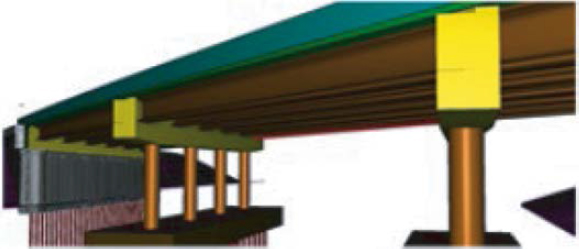
Figure 3-1. 3D BIM model of I-80 bridge.
After piloting the model-based contracting approach on a small CMGC project, UDOT pursued the process on projects with increasing levels of complexity, including an interstate project. At the same time, the agency performed two DBB projects with the model as the legal document. UDOT has continued to use this model-based delivery strategy over the last five years and expanded the approach for all project types. Currently, UDOT uses mobile devices to access needed information in the field, and no longer develops cut sheets for the projects. The first project performed without cut sheets was 90 South, a landmark for UDOT.
More recently, UDOT received a grant to focus on the development of a detailed GIS approach to collecting, managing, and using asset information for lifecycle asset management. This expansion into the coordination of final asset information will help UDOT improve its information management within the asset management phase.
Overview of Case Study Projects
UDOT has awarded 14 projects using modeling to create the legal document. Five of those were CMGC, and seven have been done using cut sheets. The following three projects were identified by UDOT as examples for review during this case study:
- I-80 auxiliary lanes;
- SR-68, Bangerter Highway to 12600 South; and
- SR-209, 90th South to 7th East.
These case study projects are representative of the scope of work performed by UDOT. One project example is shown in Figure 3-1 and Figure 3-2. UDOT typically performs projects that
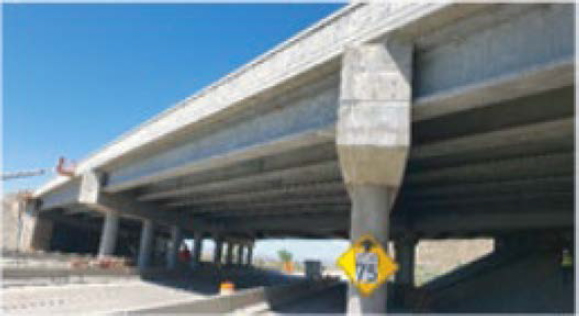
Figure 3-2. Actual I-80 bridge after construction.
range from approximately $5 million to $50 million for DBB delivery. In rare instances, the agency might implement a project approaching $1 billion using CMGC or DB delivery.
BIM Requirements Overview
As discussed earlier, UDOT defines the design model as the contractual design, thus requiring the construction to be consistent with the design model. Currently, UDOT has digital as-built requirements, but the agency is continuing to develop its ability to leverage information for asset management. Contractors are required to give UDOT an as-built model developed from the original design model, although there are remaining QC concerns regarding model updates. UDOT also has additional electronic submittal requirements, but the quality of these submissions remains inconsistent. UDOT continues to expand its efforts in these areas.
BIM Uses
BIM Use Cases
- Capture existing conditions.
- Author design model.
- Estimate quantities.
- Layout and AMG.
- Coordinate design models.
This section provides information on the primary BIM uses that are frequently adopted or required on UDOT projects.
- Capture existing conditions. UDOT has used lidar (light detection and ranging) for the past 10 years as a tool to collect information on existing conditions for projects. Lidar enables project teams to capture aboveground features and geospatial locations on the site. On many projects, they are also using drone imagery to create photogrammetry models. They expect to get information from design to construction for an existing condition database. In the future, they are expecting to leverage their as-built models to support existing conditions modeling.
- Estimate quantities. UDOT performs detailed QTOs from the models. Project teams have found the quantities to be accurate, and through collaboration with design and construction professionals, they have also found greater levels of trust in the quantities. They are continuing to develop their use of these quantities in the bidding process.
- Utilize layout and AMG. The contractors are leveraging 3D geospatial information for automated equipment guidance. UDOT can provide the contractors with the actual geometry created with the modeling process. The surveyors can extract the information needed from the 3D models and perform QC on the data. These data can then be used for AMG and for general layouts within surveying equipment.
- Coordinate design models. The design models are coordinated to remove any potential field conflicts between various design elements in the model. This can include newly designed assets or existing conditions.
Benefits and Costs
Researchers interviewed agency representatives and the design team separately. The following section is a summary of the identified benefits and costs.
Benefits
- High-quality design. One of the identified benefits is the higher quality of the overall design model. There are many elements integrated into the 3D model, including utilities, drainage, and sections grade, and therefore a detailed conflict analysis can be performed to ensure the quality and accuracy of the 3D model. In addition, the model allows for high-quality visualization, which facilitates decision-making.
- Time savings from avoided design rework. By developing the 3D model, potential conflicts can be identified early, during the design phase. This helps avoid the need for more detailed design rework compared to a more traditional process, where conflicts may be identified later.
- Cost savings from avoided change orders. With BIM, project teams can identify issues that are typically not found until construction, so they have significantly fewer change orders during the project, specifically regarding clash detection. In the SR-209 (90th South) project, there were very few change orders. Decision-making is easier when everything is transparent and visible in a 3D model. UDOT has also gained more accurate quantities from the BIM process.
- Time savings from improved design efficiency, including parametric design and avoided design rework. In the agency’s previous traditional design using CAD, UDOT spent 50 percent of the time on developing the design and 50 percent on sheet production. UDOT now spends far more time on design (which is positive), and less time is spent on drawing production, which leads to fewer reworks. With a more accurate design, UDOT can be more precise in identifying what is needed rather than overestimating and purchasing more than is needed, which translates to direct dollar value.
- Time savings during construction inspections from utilizing 3D digital design data. When everyone uses BIM with proper training, information is centralized and more easily accessed through digital retrieval on mobile devices. It can be easier to track certain information, turn on and off certain features in GIS or BIM, and navigate by using the software. BIM makes it easier to edit designs in the field (i.e., while looking at the project). It is easier to track up-to-date locations in the plans using local GPS when workers are in the field, and it saves time to see information on one screen instead of looking through plan sheets.
- Time savings on completing design quantities. The amount of time required to develop QTOs for the projects has been reduced. In addition to model-based take-offs, rovers are sometimes used to collect actual field data for quantity analysis. Whenever there is a quantity dispute, pulling data from GPS aids in timely resolution.
- Improved worker safety during maintenance and operations inspections. UDOT representatives believe this is a likely benefit, but they do not know how to quantify it. Even though maintenance crews have been using drones for inspection, they do not have quantitative data to demonstrate safety improvements. However, the use of drones allows for additional inspections.
- Time savings for agency staff from not having to track down as-built information for scoping projects. UDOT saves staff time on project scoping by using UPlan, a web mapping application in which asset data are stored and available for anyone to access (including the public). UPlan contains information about the state’s transportation plans for construction improvements, pavement management, safety and crash analysis, bridge locations, bike lanes and routes, and more. Some project teams use UPlan to access information and view an asset with the layers of data selected, which helps with clash detection. UDOT aims to transition the database from static to real time for asset maintenance. UPlan is not mandated to be used for all projects, so at first only a few regions used it. As project teams have started observing how UPlan makes looking up data much easier, more regions have started using it.
- Cost savings from avoided change orders. UDOT has seen fewer change orders for design errors and omissions since adopting BIM. Most importantly, BIM has facilitated communication and coordination between different disciplines, which resulted in reduced numbers of change orders. The adoption of BIM also caused a reduction in material overruns, which led to cost savings from the optimization of construction material use.
- Cost savings from improved project schedule/accelerated delivery. UDOT has not noticed accelerated project delivery that was directly due to BIM implementation, but the agency has seen improved design schedules. It is faster to accomplish the tasks with BIM, but project teams frequently invest the time savings into developing more detailed and improved designs. Acceleration of the construction process is more likely in a DB project than in a DBB delivery approach. UDOT is continuing to explore approaches in this area.
Costs
- Additional spending on IT resources or infrastructure for BIM. UDOT has incurred additional software investment costs, and the agency pays each year for additional digital storage. UDOT has seen some cost savings from reduced paper since adopting BIM, but this reduction was small because the agency had already transitioned to a paperless process before transitioning to BIM. UDOT has not seen any avoided operational costs due to geometric analysis because the agency had been using InRoads and modeling for about 20 years before BIM adoption.
- Cost of initial comprehensive staff training. There is an initial investment of staff time required for training. UDOT has internal training within the GIS department, and sometimes staff perform training with outside contractors. BIM authoring software training led by the software vendors is another incurred cost. Training has been conducted virtually, including two courses for internal training on BIM design: one for primary users and another for advanced users. Each course lasts four workdays, for a total of 32 hours per course. UDOT also provides internal training on how to use GIS tools when a project starts. UDOT also maintains a website with suggestions for digital delivery. UDOT has contractors train inspectors in the field.
Challenges and Lessons Learned
The top challenges identified by UDOT and project teams were staff training and learning curves.
- Staff training. Training is a struggle from several different aspects. It is complicated and challenging to train agency staff as software continues to be frequently updated with new features. UDOT aims to train staff when they are not as busy. However, as their programs have expanded, they have had several simultaneous projects, which limits the time available for training. The agency also sometimes places training responsibility on a contractor. For example, UDOT uses GPS equipment for inspection tasks, and contractors are required to offer 50 hours of training to the field crews on use of the equipment.
- Learning curves. Sometimes there is an issue with a contractor’s learning curve and desire to revise existing methods. There is a higher upfront time investment required when learning how to use new processes and tools.
The following list includes some of the lessons learned that were shared by UDOT and project teams.
- Continuously requiring new human tasks can be limiting. UDOT is interested in leveraging new technologies, such as machine learning, to aid in improving the agency’s process using an automated approach.
- Not enough time for clash detection. With fast design schedules, it can be difficult for project management staff to allot the time needed to effectively coordinate the design.
- Not enough confidence with using BIM. There is still a challenge with some designers not trusting the modeling software, which can reduce efficiency in modeling.
3.4 Case Study 3: Colorado Department of Transportation—I-70G Edwards Spur
Introduction
CDOT has been using 3D model-based design for roadways for a long time, and the agency is moving toward inclusion of 3D models from other disciplines, such as drainage and dry utilities. So far, CDOT has not officially implemented a BIM program. This is mainly due to
a lack of awareness on the multiple benefits of BIM. CDOT’s construction program typically includes maintenance-type projects, such as resurfacing and pavement repairs and bridge rehabilitation.
However, CDOT is in the process of implementing its collection of digital as-builts, a BIMspecific use case, as part of FHWA’s Every Day Counts initiative, round six. Digital as-builts are considered living records that are updated during construction to support effective lifecycle asset and performance management. Specifically, one of CDOT’s main motivations to implement digital as-builts is to mitigate utility strikes during construction. The CDOT digital as-built program is thus a prevention management strategy to improve safety and save costs associated with such incidents.
The department is in the process of building a statewide digital as-built database in which subsurface utility records will be hosted to make the data available to project teams in the future. CDOT anticipates that the initiative to establish, populate, and create a data management plan for digital as-builts will take approximately five years. It is CDOT’s desire to incorporate data from design and construction, including permitting and existing CAD and legacy utility information. CDOT’s vision for a mature subsurface utility system of record is to use the information to verify or supplement field surveys.
Case Study Overview
CDOT has funded several projects within the I-70 corridor to improve many intersections, as this is a critical corridor within the interstate system. It is a tourist travelway with many connectors and great importance to the community. The I-70G Edwards Spur Road Improvement, Phase II, is one of many I-70 corridor improvements. An atypical project for CDOT, Phase II of the I-70G Edwards Spur Road Improvement leveraged BIM for design, construction, and record modeling. This $21 million project was funded for improvements to the intersection of I-70G Spur Road and U.S. Highway 6, which included converting a signalized intersection to a two-lane roundabout; replacing one bridge and widening another; and installing pedestrian bridges, a drainage network system, lighting, signage, striping, and guardrail. The scope also included roadway widening, along with utility upgrades and relocation. The project was delivered through a CMGC delivery contract. The construction phase was completed in October 2020, approximately two years after initial groundbreaking. This project has recently been awarded the Colorado Department of Transportation Best Environmental Project.
BIM Requirements Overview
CDOT does not currently have any agencywide BIM requirements that are adopted on every project. The design team used the 3D-design capabilities of the software to create corridors, surfaces, and solids of infrastructure objects to perform clash detection and prepare traditional 2D plan sets. CDOT is investigating the development of a set of core BIM requirements. To date, CDOT has invested in the development of a subsurface utility and drainage analysis library, containing standards for 3D objects for drainage and utilities, to be used in future projects.
BIM Uses
BIM Use Cases
- Author design model.
- Analyze engineering performance.
- Coordinate design models.
- Author 4D model.
- Compile record model.
Although CDOT does not have extensive experience with BIM, the project team decided to use a 3D model-based design approach beyond the traditional roadway modeling as a risk mitigation strategy. The team modeled more than is typically done on a CDOT project to understand the location of utilities and coordinate elements of construction related to phasing. The team started with an existing condition model created from aerial lidar and ground survey data.
The existing condition model included traditional survey mapping deliverables, such as a digital terrain model, or 3D surface, and 2D geometry displaying the topographic features. There were no 3D reality models or 3D solids requirements for survey deliverables for this project.
The design team created 3D models for bridges and other structures (e.g., retaining walls), roadways, subsurface utilities, and drainage. During design, the only data property added to the 3D modeled objects was the utility owner information. The 3D model was helpful in automating the calculation of earthwork quantities needed for construction phasing of the roundabout, but due to the limitations of the technology being used (i.e., Bentley’s InRoads SS2), the team used traditional 2D methods to estimate other quantities.
The most beneficial use of BIM on this project was the ability to analyze the engineering design. Traffic modeling showed that the peak traffic time was during the school year. Because this was the main road to take kids to school, the project had to be completed over the summer (10 weeks). A major component was the ability to visualize the design alternatives between the original signalized intersection and the proposed two-lane roundabout. Visualizing traffic movements was helpful for the design team to understand how traffic could be least impacted during construction. Coupled with this analysis, the use of BIM becomes increasingly more valuable when it is used for coordinating work or activities.
The CMGC delivery approach gave the project team a unique opportunity to work with the contractor during the design of the project. The design team held working meetings with the contractor to get as much input as possible. During these project team meetings, the 3D model was used to identify the best construction phasing approach. The model was put on the screen and the designer walked through the 3D model to help the team make decisions in real time. It was through this process that the team was able to review various design alternatives to manage the construction phases for the roundabout area. The roundabout construction portion of the project was originally scheduled to take place in four phases. Through the use of BIM, the team was able to find design alternatives and traffic phasing that allowed the construction to be reduced to only two phases. This two-phase construction option helped to reduce time and project cost, providing a more positive traveling experience for the public.
A new effort within CDOT related to use cases is the approach the department took to record the as-built model of installed utilities. CDOT is in the process of implementing specific data collection requirements for digital as-built information for utilities and buffer zones. The department is piloting a new system in which data from the model will be pushed to a mobile application during construction. Because this effort to collect information for digital as-builts is new at CDOT, the project team was only able to collect a digital as-built for the waterline work. The data collected with GPS technology was imported into a legacy database instead of the new system.
This new digital, as-built system is based on GIS technology. Field staff were equipped with GPS equipment for field data collection. The new CDOT system, which the department calls PointMan, is a GIS database developed in-house for use by field construction personnel. Trimble Catalyst, a geospatial application that uses a GPS receiver connected to a mobile device, will be used to collect precise GPS positions for each asset location. CDOT will be connecting the information collected in the field from Trimble Catalyst to PointMan to obtain an accurate record of the asset locations.
Benefits and Costs
The following list includes benefits and costs identified by the agency representatives and design team.
Benefits
- Time savings from improved design efficiency. The project team estimated staff time savings between one and two weeks (about 40–80 hours) from using BIM. Design team members indicated they were able to avoid multiple roundabout redesigns by working within a 3D environment. Although the design team had a learning curve on this project because team members were new to BIM, they were still able to expedite the process of design updates. Visualization of the design is powerful and allows the design team to make updates to the design more efficiently. The design team indicated that the process will become more efficient once everyone reaches proficiency in using the BIM software. Another area that translates into improved design efficiencies is coordinating BIM and CMGC processes across disciplines. Since the project team had many sessions to coordinate on models, it is hard to estimate the amount of time savings due to this coordination. While clash detection can be performed without using BIM, it is an extremely time-consuming process that requires the designer to manually look for utility conflicts. By using BIM clash detection, design team members estimate they may have saved about one week.
- Time savings from improved design efficiency, including parametric design and avoided design rework. While this particular benefit was not observed directly on this project, the design team indicated the new BIM design software has new functionality that includes dynamic parametric design. This means that every time a design change is made to the controlling geometry, the software automatically propagates the changes throughout the design files. This enhanced functionality in the software will result in significant time savings in future projects. The team used traditional design software to design road corridors parametrically. This functionality has been in the software for decades, but the parametric design had been limited to pavement layers.
- Cost savings from avoided change orders. The use of 3D modeling for existing and proposed underground utilities enabled the design team to perform clash detection, which helped to mitigate potential field conflicts during the design phase. In this project alone, there were 123 different conflicts identified during clash detection. A clash detection report was produced directly from the authoring software (InRoads SS2) to provide a clash detection matrix to be used for utility coordination. The team was able to adjust during the design phase to eliminate conflicts. Project team members estimate they might have only identified about one-third of these conflicts without using BIM. They also attributed the reduced conflicts to the CMGC delivery method, which allows for an extra set of eyes on the design. However, they are unsure how much of this clash detection improvement was due solely to BIM because both the designer and the contractor were able to collaborate to identify these risks and make corrections quickly. This corridor was in a location of high risk for underground utility conflicts. The design team estimated that each conflict would have cost between $5,000 and $50,000. The project team estimated that a magnitude of up to $1.5 million in conflicts (high end) was avoided. This estimated value assumes the worst-case scenario, which would include moving the utility entirely rather than addressing each conflict individually. It is important to note that during this project, there was only one change order, in the value of approximately $5,000 due to utility conflict, which is highly unusual. For example, on another project with similar circumstances, CDOT experienced a higher number of change orders and overall cost. Although it is difficult to put a value on it or equate a change order to damage prevention, CDOT staff indicated it is valuable to leverage BIM for this purpose.
- Fewer quantity overruns. Earthwork quantities can frequently cause conflict on a project, but staff indicated this was not the case for this project. The designer indicated all earthwork calculations were directly derived from the model. Some project staff members mentioned
- Cost savings from improved schedule management. The most significant benefit achieved through BIM was the improvement and acceleration of the project. CDOT was able to use BIM to optimize the schedule by reducing the number of phases specific for the construction of the roundabout. The impact to roadway users was also minimized.
- Cost savings from optimization of construction material and design options. The project team was able to influence scope optimization by evaluating multiple design options. Specifically, the design team used BIM to optimize profile changes and minimize the amount of pavement material for the road. The material savings enabled the project team to switch the budget to replace the bridge, instead of widening, without any significant budget increase. It is important to note that the long-term benefits outweigh any immediate project benefits, as the agency was able to optimize the overall lifecycle cost of the structure. Instead of repairing a bridge that would have needed regular routine maintenance due to its age, CDOT was able to construct a new bridge that has a 100-year lifespan.
- Safety benefits. Other benefits of design optimization due to scope change include safety benefits for bike/pedestrian lane users by adding a separate bike/pedestrian bridge and removing it from an at-grade condition. The 3D model enabled the designers to analyze the design and provide the best possible solution to place pedestrian facilities in this heavily traveled roadway. The project was completed at the same cost, with more savings over the bridge’s lifecycle due to the use of BIM to analyze design performance.
- Time savings from avoiding the search for as-built information during operations in the future. This is one of the most significant BIM benefits identified by the project team for the future. CDOT wants to leverage BIM for accurate, reliable digital records. This will help the agency with investigations in the future, including what happened, when it happened, and how it happened.
earthwork quantities on this project were relatively straightforward, and they did not have any issues with the contractor regarding those quantities.
Costs
- Initial BIM hardware investments or upgrades. As CDOT deploys the new OpenRoads Designer (ORD) software, it may be necessary to purchase new computers that can handle the additional processing requirements for BIM visualization and parametric design modeling.
- Staff training. The agency is expecting to incur initial training costs to bring all project teams internally up to speed with the new ORD Connect software. The upfront training will take approximately one week (40 hours) for the designers who perform roadway modeling.
Challenges and Lessons Learned
In general, this project is considered to be very successful. BIM was used as a tool to communicate the design intent, find the best design solutions to ease congestion, and improve safety along the corridor. All project stakeholders were pleased with the results of the project, and CDOT received very positive feedback.
The top challenge identified by the owner and project team was learning curves. The biggest challenge for the design team was learning the process of model-based design. There was a lot of experimentation and new concepts to learn and put into practice. Once everyone achieved BIM proficiency, the team was able to realize more benefits.
One lesson learned that was shared by the owner and project team was staff training. Because BIM is new to CDOT, it would be beneficial to evaluate an overall training program that incorporates the use of technology (ORD software), effective processes and methods for BIM, and the value of using modeling standards.
3.5 Case Study 4: Denver International Airport—Hotel and Transit Center Program
Introduction
Denver International Airport (DEN) in Colorado first opened in 1995, capturing attention with its unique structural design and use of technology. In 2019, DEN serviced 69 million passengers. As of 2021, DEN is the fifth-busiest airport and the largest in terms of area (53 square miles) in the United States (Ball 2015). DEN generates more than $33.5 billion in revenue for the region every year, making it Colorado’s largest revenue generator. Originally built to service 50 million passengers, the airport has increasingly been exceeding its original capacity and is in need of major expansion. There are many ongoing large projects, including expansion and enhancement of Concourses A-West, B-West, B-East, and C-East. Work also includes improvements to the existing infrastructure in each concourse. There are approximately 80–200 ongoing concurrent projects, including civil projects (Denver International Airport n.d.).
DEN was one of the early adopters of BIM among airport agencies. The BIM journey dates to August 2007, when the agency recognized the need to collect as much information about its assets as possible. The main objective of the DEN BIM program is data collection for improved decision-making, specifically for preventive maintenance of airport assets. DEN began implementing BIM in 2010 with its Hotel and Transit Center (HTC) project, the first of many expansion projects to increase airport capacity and operational service. While at first the BIM implementation was very project-driven, the agency has since mandated the use of BIM on all its projects, institutionalizing its use in all lifecycle phases (McCuen and Pittenger 2016). In addition, the airport authority has invested in an organizational BIM deployment strategy that enables the standardization of project deliverables by leveraging in-house resources to manage the overall program. BIM program staff provide technical support, assist with project prioritization, develop and conduct training, and assist project teams with the BIM process.
Case Study Overview
This case study focuses on the use of BIM during the HTC Program. This $720 million project included the construction of a commuter rail transit center and a 519-room hotel. DEN chose to pilot BIM on this project as a strategy to manage project risk. BIM has proven to be beneficial on large and complex capital improvement projects like the HTC Program. DEN hoped to realize the benefits promised by the BIM model-based approach, including improved collaboration between disciplines and avoidance of change orders. The project size, scope and complexity made it ideal for a BIM model-based approach.
The project used the CMGC delivery method. The design team collaborated with the contractors during the design phase to receive input and adjust the design.
BIM Requirements Overview
Like many large institutional owners, DEN started its BIM implementation without the use of any BIM requirements. In the absence of DEN-provided BIM requirements, the design firm used its own standards to develop design models. In 2009, DEN hired a BIM consultant to help develop the agency’s first set of standard BIM requirements. BIM requirements for civil works were added to the standard requirements in 2016 and 2017. As of 2021, DEN has a complete set of standards for the use of BIM published in Design Standards Manual: Digital Facilities and Infrastructure. The manual provides minimum requirements for the use of BIM on all design, facilities, and infrastructure projects at DEN, including
- Policy regarding the information management process,
- Information modeling requirements,
- Project execution planning,
- Modeling standards and naming conventions,
- Plan preparation and technology procedures, and
- Quality management best practices.
BIM Uses
BIM Use Cases
- Author design model.
- Create quantities and cost estimates.
- Coordinate design models.
- Author 4D model.
- Inspect constructed asset.
- Compile record model.
Several primary BIM uses are frequently adopted or required on DEN’s projects (see BIM Use Cases text box).
BIM was implemented in the design phase as much as possible within the project’s organizational and contractual structure. While the design model was used to create quantities and cost estimates, it was difficult for design teams to trust the calculations performed under their new approach. BIM was implemented for 3D coordination to improve design accuracy. This was accomplished through the strong leadership of key design champions. BIM information made creating sheets from models easier, although that was not the case at first. However, by the end of the project, all sheets were created from the design model. Although drawings were the contractually binding documents, models were still shared with constructors. Surprisingly, these contractors were more comfortable with BIM than DEN expected, although there was an inconsistency of tools used for developing 3D models between contractors and the design team. The design team used Revit while the contractors used 3D CAD tools for reviewing and developing 3D models.
The 3D models and the construction schedules were used to develop 4D models to visually track the progression of construction. BIM was also used as the primary source of data for FM during operations. DEN personnel were able to access asset information. Examples of information that was available through BIM data exchanges include date of purchase, cost, specific asset location, when it was installed, and the maintenance schedule.
The BIM program launched as part of the asset management program, although there was no coordinated program before 2012. The BIM model was used for “everything” related to an asset. The 3D models were used for maintaining critical systems—mechanical, electrical, plumbing, and security. The process focused mainly on developing a detailed model to inform all ongoing actions instead of creating visualizations. DEN’s priority in implementing BIM was to capture asset tracking. Then DEN pushed information into the GIS (a priority use) and information for downstream tenant projects (tenant improvements or renovation). For example, there are frequently tenants that will be performing projects within a space soon after projects are delivered, and the ability to provide a detailed model to the designers of these projects is very valuable. Design-intent models are continuously updated as new projects are performed.
Benefits and Costs
Researchers interviewed agency representatives, and the following section is a summary of the identified benefits and costs.
Benefits
- Cost savings and avoided time spent tracking down information needed for routine maintenance. The BIM process employed for the design and construction of this project greatly improved ongoing FM and maintenance. DEN’s efforts to implement BIM for maintenance are strategic for long-term benefits. With BIM adoption, the building model was
- Cost savings from reduced paper and reduced physical storage needs. Without coordinated models, DEN would have needed to collect, store, share and secure thousands of paper documents (plans and specifications) onsite. Not only was a great reduction in paper redundancy achieved by electronic file sharing, but also the possible need for a trailer for drawings onsite was eliminated.
- Time savings in document review and approval due to faster turnaround time by using cloud-based software. BIM contributed to staff time savings. Updating the digital drawing sets through BIM technology saves time for all parties compared to physically updating plan sets. It was estimated that document review and approvals using BIM helped reduce approval time by up to 20 percent.
- Improved worker safety and time savings during maintenance and operations inspections. Since documents are always up to date and accessible, commissioning information and linked documents can be used as the deliverable for handover and facility operations. The field data management system compiles quality, safety, and commissioning checklist results. Gathering quality assurance/quality control (QA/QC) information can help proactively identify trends and minimize risk for the contractor and project. BIM helps to create work-to-complete lists for traders and other parties. Modeling also helps with time savings because more punch list items are completed earlier through the effective management of issues and checklists in the field. Checklists help make inspections faster, more consistent, and more thorough.
- Improved worker safety during construction inspections due to increased use of automation and having workers onsite for a shorter duration. BIM provides automated, bidirectional information exchange between the BIM model and the FM platform, which significantly reduced risk and resulted in time and cost savings on accuracy. Digital mobile devices like iPads allowed for updating coordinated models and sharing electronic files, making models accessible to workers and trades. For workers actively involved in an onsite task, such as tying rebar, visualizing the 3D model via an iPad, panning around, and seeing the plan in context to where they were standing were perceived as positives. The time savings and increased safety achieved by reducing workers’ exposure to live working zones were far beyond dollar values. For example, by viewing the model on an iPad, a worker can pre-inspect the work without being exposed to a live working zone. Everyone involved in the activity can easily visualize the model and understand how their work fits into the overall process, and therefore identify problems well in advance (Ball 2015).
- Time and cost savings from avoided change orders. BIM promoted the development of a fully integrated FM workflow, which provided opportunities for housekeeping and content management. Digital transition engaged all disciplines (i.e., civil, infrastructure, and vertical design, as well as construction groups for each of those) through the lifecycle of the project. There were fewer issues due to communication between constructor and designer during the design phase. With a seamless flow of models, disconnects between the design and the final finished buildings do not exist, overcoming issues around ownership and liability. BIM enables collaboration among different disciplines, reducing the time and cost that jobsite changes would cause otherwise (Ball 2015). Cloud-based BIM management solutions transform BIM collaboration by simplifying multidiscipline model coordination and clash detection and providing access to BIM models and intelligent object data anywhere for the entire project team. It helps architects, engineers, owners, and builders across the globe collaborate in real time in more than 50 different file formats. Clash detection in ductwork and piping led to significant time reduction and cost savings in construction. Significant issues of building performance occur because of isolations among different disciplines in traditional management
carried throughout the whole lifecycle of the project, leading to reduced redundancy. In the HTC Program, DEN implemented BIM for daily asset management of the entire airport facility with hopes that the BIM system will make maintenance of the airport infrastructure more efficient, which in turn saves time and money and improves quality.
- Time savings from reusing previous BIM content and experience. In-depth feasibility studies based on a detailed model of what currently exists can help avoid lengthy and expensive consultant time on feasibility studies in the future, which adds to significant time savings (Ball 2015).
- Reduced frequency of non-scheduled maintenance due to improved BIM collaboration processes. DEN has been doing a better job at tracking the types of maintenance being done and the associated costs, although not all assets are created with BIM. DEN determined that corrective maintenance costs five times as much as preventive maintenance on a person-hour basis on an airportwide scale. Therefore, DEN’s goal is to reduce the amount of corrective maintenance required. For each 5 percent reduction in annual corrective maintenance, $5 million in cost savings will be generated.
methods. For example, jobsite changes can impact mechanical performance when they are not entirely constructed as designed. As a result, rework is costly and time-consuming if a contractor installs the ductwork and piping differently. Besides, identifying design issues in early design review provides significant savings by modifying the design phase compared to redoing the work later. DEN has already saved 6,000 hours in labor by creating O&M asset information in Maximo. BIM allowed DEN to shave three months off the schedule for the HTC project. BIM 360 Glue Coordination saved 8 hours per worker per week in design and construction (8,000 hours saved in total). BIM 360 Field saved 2 hours per issue and 1,100 hours in the first six months. It has been reported that BIM reduced RFIs, change orders, and rework by 40 percent (Autodesk n.d.).
Costs
- Software costs. DEN estimates that there were additional BIM-related software costs incurred due to the new BIM 360 platform. These are annual costs on top of software subscription costs prior to implementing BIM.
- Hardware costs. DEN also incurred additional hardware costs, including a lidar scanner.
- New staff positions. New staff positions were required to support the BIM program. While several of these positions were filled by existing staff, three new employees were hired to support the program.
Challenges and Lessons Learned
The following section lists top challenges identified by DEN.
- People and inertia. People were identified as the most significant challenge, and the second biggest challenge is inertia because people tend to be resistant to change. One example provided was that while the model can be used to create quantity and cost estimates, it was difficult for design teams to trust the calculations performed under the new approach.
- Lack of sufficient and valid historical data. A change management process is needed when implementing BIM because ROIs require valid historical asset data (McCuen and Pittenger 2016).
- Learning curves. Learning curves are an issue, especially for new providers. While there are clear benefits to learning new processes, there are also many hurdles. The education process matters because people need to remain engaged as things develop in order to catch up with technology changes. Things could fall apart if project timelines are as long as two or three years (the average learning curve for an organization) and there are no technicians to follow through.
The following section includes some of the lessons learned that were shared by the owner.
- BIM requirements. The bid process has become more inconsistent with the addition of detailed BIM requirements; since some organizations are still not familiar with BIM processes, there can be large variations in cost projections in estimates. DEN aims to address this issue through
- BIM requirements need to evolve. BIM processes and methods continue to mature, therefore BIM standards need to be continuously reviewed and constantly evolving. Staff also must stay up to date on the latest standards, and training may be required.
- Increased design fees. There is a significant difference in design fees between BIM-savvy designers and those who are not savvy with BIM, which can be attributed to the anticipated BIM learning curve for designers and clients who lack experience with BIM tools and processes.
outreach and by simplifying BIM requirements. DEN is seeing experienced companies lowering costs, especially for designers. Contractors are also lowering prices but at a slower pace. MEP/Arch designers shared a 40 percent reduction in their costs from their early experience working with DEN requirements through the current requirements. There were also significant reductions in costs associated with certain required tasks, such as laser scanning.
3.6 Case Study 5: Highways England—A556 Dual Carriageway
Introduction
Highways England is a government-owned company and the largest road authority in the UK. It works closely with the Department of Transport and operates as a company on behalf of the UK government to maintain the Strategic Road Network.
Highways England’s BIM journey dates to 2011, when the UK first mandated the use of BIM on public projects. BIM was first used during project delivery to improve the management of large, complex projects. During the early planning, efforts were not supported by a dedicated budget or strategic plan for BIM adoption and execution, although more recent efforts have supported the planning initiatives.
The construction industry in the UK saw the opportunity to use BIM as a risk management tool and adopt more integrated project delivery approaches, such as DB delivery. Costain, a contractor in the UK, sought to use BIM to deliver projects better, faster, and cheaper. In 2012, a Lean Six Sigma group was developed within Costain to investigate the company’s BIM deployment strategy. Part of this evaluation included smaller working groups to investigate technologies, such as 3D modeling and Common Data Environment (CDE) processing. The company started to transform its process from developing CAD standards to adopting BIM processes. The adoption of BIM by Costain on highway projects was accelerated due to the government mandate for BIM Level 2 requirements that was released in early 2016.
Case Study Overview
This case study is based on the highway project A556. The site is in Cheshire in Northwest England. This 7.6-kilometer stretch of highway serves as one of the primary routes into Manchester City. The project objective was to expand the highway capacity of the congested corridor and improve the geometry of the 7.6-kilometer section connecting the M6 Junction 19 near Knutsford with the M56 Junction 7 near Bowdon. The project was procured as a DB delivery, a newer delivery approach for Highways England. The scope of work included significant roadway work to convert the existing undivided highway to a divided facility. Also, the project included the construction of seven new bridges, one pedestrian underpass, and refurbishment works to two existing bridges (England Highways Agency 2014). The total project cost was £200 million, including the construction cost of £107 million. The timeline included three phases: 1) 18-month planning phase; 2) 18-month design phase; and 3) two-year construction phase.
BIM Uses
BIM Use Cases
- Author 3D model and design review.
- Estimate quantities.
- 3D coordination.
- Automated machine guidance.
- Record model/digital as-built model.
Several primary BIM uses were frequently adopted or required on this project, as seen in the following examples.
Author 3D Model and Design Review
From a technology standpoint, the initial bridge and highway design models were developed by the design engineers on this project using 3D parametric modeling software. The bridge models were then exported into openBIM data files (IFC) to allow for further design review. The designs were reviewed by leveraging a nonproprietary 3D viewer to show design, properties, and ownership (Petri et al. 2017). The team delivered the design through a federated 3D model.
A new approach was adopted by the design engineers for this project. To meet the project schedule, the design needed to be complete prior to starting construction. This required revising the detailed 3D modeling process, the overall design process, and design reviews with stakeholders, which helped to identify potential future issues.
One benefit of this approach was the identification of a massive utility that would have been diverted around if discovered later. The design team was able to demonstrate the value to the owner of leaving the utility in place because of the modeling approach and investigation of existing utility locations, since the entire team could visualize the utility conditions and impact. This decision is estimated to have saved £1 million in cost with reduced redundancy since they were able to plan properly. Without this process, they would have diverted around the utility. The lead designer perceived that early contractor involvement, with the right parties on board from the outset informing the design, makes a huge difference.
Estimate Quantities
The construction team performed some 3D modeling during the construction phase, partially focused on developing the target price for the construction estimate. This model content was then used to develop and extract quantities for the estimated costs. One example provided by the team was related to the modeling of fencing. On a typical project of this scale, it might take three days to perform a detailed take-off of the construction fencing; but after developing the model, the take-off only took three minutes to extract the modeled quantities.
3D Coordination
The IFC models of the bridges were used for performing detailed 3D coordination. The models were used within an automated collision detection software to identify 3D geometric clashes. The clashes were then resolved prior to construction.
The contractor reflected upon a previous project for which the management of RFIs was a full-time job, referring to the previous project as “chaotic.” This was avoided in the A556 project by getting parties involved earlier and leveraging model content to resolve design coordination issues. The construction team’s familiarity with the design early in the process cascaded through the rest of the team. Few problems were identified with the early involvement of everyone in the pre-construction work except for unforeseen factors, such as unknown utilities.
Automated Machine Guidance
In the construction phase, the constructor used AMG for equipment operations. The process focused on leveraging the 3D model as an input, along with some post-processing routines, to extract a terrain that could be leveraged by the AMG software. There are no current minimum requirements for delivering AMG information to constructors. Construction industry practitioners speculate that if a set of standard minimum information requirements were adopted by
the owner, the resulting process would create greater efficiencies, which would help drive down prices for equipment operations.
Record Model/Digital As-Built Model
Throughout this project, design and construction teams developed the model to include asset data and leverage template parametric content libraries within the 3D software. After completion of construction, the teams performed an extract, transform, and load process to transition the data from the design model into the asset management system. The operations phase was managed by leveraging GIS data, which is populated from the content within the 3D models.
Benefits and Costs
The following section contains a summary of the identified benefits and costs based upon an interview with team participants.
Benefits
- Time savings from avoided RFIs due to improved clarity of design. There was an estimated reduction of £2,500 for the administration costs of each RFI as well as savings from avoided rework and design changes. The number of RFIs was significantly reduced compared to a traditional contract. There was no overall estimated impact on the schedule critical path, but some time was shifted from construction to the design phase.
- Cost savings from optimization of design options. The design team was able to use the model to assess safety sightlines for selecting the placement of variable driver information signs. The safety audit process was enhanced by using automation for selecting and reviewing the sign placement. While it took some effort and time to automate the safety audit, it eliminated potential rework that typically results in higher costs.
- Avoided vehicle crashes due to safety simulation with BIM. BIM provides a higher level of visualization to identify potential safety issues, thus reducing the probability of vehicle crashes. The use of BIM on this project resulted in an increase in safety performance on the operational highway. The team was not able to estimate the financial value of this benefit, which only partially originated from BIM reviews during design.
- Improved safety during construction. There was a significant reduction in the number of onsite staff, which should yield improvements in overall construction safety. However, there were no specific data to support the scale of potential savings.
- Improved worker safety during maintenance inspections. Some inspections are now performed by leveraging photographic information collected from unmanned aerial vehicles. Leveraging this new approach to perform an inspection could limit potential safety concerns related to inspections. However, currently the cost for performing such an inspection is higher. It is a cost tradeoff because the frequency of inspections has increased, which yields improved potential safety, and overall costs per inspection have come down.
- Cost savings from avoided change orders. Typically, projects go over budget due to problems found during construction, which require a cost change order. On this project, however, the use of BIM early in the process helped identify design issues, thereby avoiding cost changes to the contract. The A556 project was completed within the original budget.
- Cost savings from improved project schedule. Typically, projects in the UK experience an approximately 30 percent schedule overrun during the design phase. The use of BIM and the collaborative process enabled the A556 project to finish on time.
- Cost savings from optimization of construction material use due to BIM design. The project team proposed a common family of bridges composed of a standard set of components. The
- Time savings from reusing standard BIM content libraries (e.g., 3D cells, templates) for similar work in the future. The contractor started a library to use during initial or conceptual stages for common model development. The library does not yet extend into more detailed designs. The digital content library has some indirect benefits, such as accelerating BIM adoption because the private sector does not need to invest time or funding into developing a unique library. The team recommended that if clients want to benefit from libraries, they need to overcome challenges associated with insurance and potential liability. The contractor invested £100,000 to create the model library and projected a fivefold return on this investment.
- Time savings from improved design efficiency, including parametric design and avoided design rework. Parametric design was considered relatively new in 2015. The team had programming scripts for connecting data to external sources. However, starting in 2018, parametric design has become a very important topic in the highway sector in the UK. Parametric design does not just enhance speed but can also improve the quality of the design.
- Time savings in document review and approval due to faster turnaround time by using cloud-based software. To undertake the project, the team deployed a cloud-based CDE. The objective was to demonstrate the benefits of collaboration throughout the design and construction of A556 and to demonstrate that difficult linear infrastructure models can be effectively managed by a cloud-based system, to the benefit of all parties (Petri et al. 2017).
team worked with potential suppliers and leveraged models to solicit their constructability views, while also performing collaborative workshops that ultimately yielded changed profiles of bridge beams. These detailed reviews significantly reduced concrete volumes used in this project, which yielded estimated savings of £300,000.
Costs
A confidential benefit-cost analysis (BCA) was performed for this project, and it clearly demonstrated the potential for savings during the project delivery phase.
Challenges and Lessons Learned
The following list includes top challenges identified by the team.
- Defining and validating information. Highways England has been working on BIM adoption for some time, yet the company still has to consistently receive the as-built model for each project. While the A556 project was very successful, some other projects have not had the same level of success at receiving quality data from the designers and constructors. There is a need to continue building a robust quality management approach that reviews the data requirements and outlines an approach for validating the information received from each project. This will require active participation between Highways England and service providers to ensure that service providers understand the requirements and the importance of the information.
- Early information gathering could save money. Using BIM at the earliest project stages could provide significant value. One lost opportunity of the A556 project was that Highways England did not perform a detailed laser scan or photogrammetry survey at the beginning of the project. Had project team members used existing model capture techniques, along with ground-penetrating radar for utility location, they would have saved significant funding in redesign costs, with their estimate projecting a tenfold savings in the cost of the scanning. They did perform some isolated scans.
- Content library for Highways England. A content library to share with designers and constructors with more detailed content elements would be beneficial, although legal and contractual issues regarding the use of the content elements must be resolved first.
Lessons Learned
The following list includes several lessons learned.
- Collaboration is critical. It is very valuable to have the designers and contractors working together to get the right focus and the right project outcome. The whole team comes together to deliver the results, and the team needs to set single goals, mutual incentives, and collaborative working arrangements. Typically, designers working alone do not have to focus on the deadline, and they may not see the big picture. The creative design process requires iterative cycles; there must be time for creativity as well as a focus on completing the tasks. The collaborative work process can help keep everyone focused on the outcome and provide accountability.
- Parametric design is valuable. The team members felt that the expansion of parametric design concepts—leveraging predefined content libraries—will become a truly significant process disruptor. Design automation approaches will yield high-quality designs and information-rich models, as well as significantly reducing the time needed to develop designs. The contractor is investing in research and development efforts in this area.
- BIM/3D prototype was the glue. The model provided a common representation for collaboration.
3.7 BIM Expert Validation Panel
Researchers worked with a BIM expert panel to validate and confirm information collected through the literature review and case study interviews regarding BIM adoption. This expert panel was consulted to help fill in any data gaps for the ROI framework.
Specifically, the panel was asked to
- Supplement data found through literature review and case studies,
- Pull from professional experience,
- Build consensus on possible value ranges, and
- Confirm use of the ROI framework.
The panel consisted of a multidisciplinary group, including bridge and roadway engineers, asset management strategists, and BIM technical support staff from both the building and infrastructure domains.
As shown in Figure 3-3, a series of two virtual workshops were held. During the first workshop, researchers introduced the expert panel to the project objectives and desired outcomes
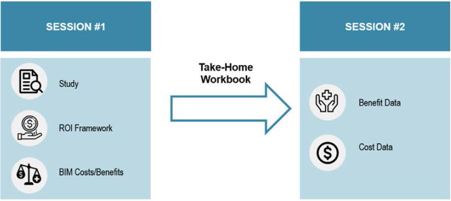
for their participation, research methodology, and preliminary examination of cost and benefit measures. At the end of the workshop, the researchers provided a data collection booklet that the expert panel could use to assist with filling in the data gaps for specific measures. During the second workshop, the expert panel reconvened to discuss specific input for each of the cost and benefit measures in the workbook.
The information collected during these two virtual workshops was used to fill in data gaps and finalize the cost and benefit data values used for the ROI framework in Chapter 4.


