Development of a MASH Barrier to Shield Pedestrians, Bicyclists, and Other Vulnerable Users from Motor Vehicles (2024)
Chapter: 14 System Details for MASH Tests 3-20 and 3-21

CHAPTER 14
System Details for MASH Tests 3-20 and 3-21
Test Article and Installation Details
The length of the test installation was 255 ft 8 in. The upstream end of the installation had a 79-ft section of guardrail and terminated at the upstream end with a steel post W-beam cable anchorage system. One section of Thrie beam guardrail was connected to the upstream end of the multifunctional rail, and a nonsymmetrical Thrie beam to W-beam connection was used to attach the upstream end of the Thrie beam to a W-beam guardrail. The downstream end of the installation was anchored with a steel post W-beam cable anchorage system that was approximately 9 ft 4 in. long. The multifunctional barrier was constructed of an HSS with dimensions of 12 × 6 × ¼ in. with its top located 32 in. above grade. The rub rail was an HSS with dimensions of 4 × 4 × ¼ in. with its top located 13 in. above grade. The rails were supported by W6 × 8.5 posts spaced at 66 in. on center.
The field side handrails of the multifunctional barrier were fabricated of HSS 1.90-in.-diameter × 0.145-in.-thick tubing. Their centers were located 35 in. and 41 in. above grade, respectively. A cane rail, also on the field side, was fabricated from an 11-gauge 4-in.-wide plate with its bottom edge 1 in. above grade.
The posts of the multifunctional barrier were set in a 19-in.-wide, 4-in.-thick continuous band of grout, with 24-in.-wide, 4-in.-thick concrete slabs on both sides. The traffic side faces of the posts were 4 in. from the joint between the concrete and grout.
Due to an error during construction prior to MASH Test 3-21 (Crash Test 612541-01-3), Post 12 (the post placed in the middle of the Thrie beam to W-beam asymmetric transition rail) had a W-beam blockout with one 10-in. guardrail bolt as opposed to the transition blockout with two 10-in. guardrail bolts that the original drawings called for. This error was corrected for the MASH Test 3-20 (Crash Test 612541-01-4), and the drawings in Appendix F reflect what was tested. Because Post 12 was upstream of the impact location for Crash Tests 612541-01-3 and 612541-01-4, the error was determined not to be a factor in the outcome of the crash tests. (Note: This opinion/interpretation is outside the scope of the TTI Proving Ground’s A2LA accreditation.)
Figure 123 presents the overall information on the multifunctional barrier transition for Crash Test 612541-01-3, and Figures 124 through 129 provide photographs of the installation. Appendix F provides further details on the multifunctional barrier transition for Crash Test 612541-01-3. Drawings were provided by the TTI Proving Ground, and construction was performed by TTI Proving Ground personnel.
For Crash Test 612541-01-4, the section of the multifunctional barrier that was the farthest upstream was removed, and the concrete and grout were cut out because of damage from the previous test, Crash Test 612541-01-3. This removal shortened the overall length of the installation by 16 ft 6 in., making the total length 239 ft 2 in. All other details of the installation remained the same.
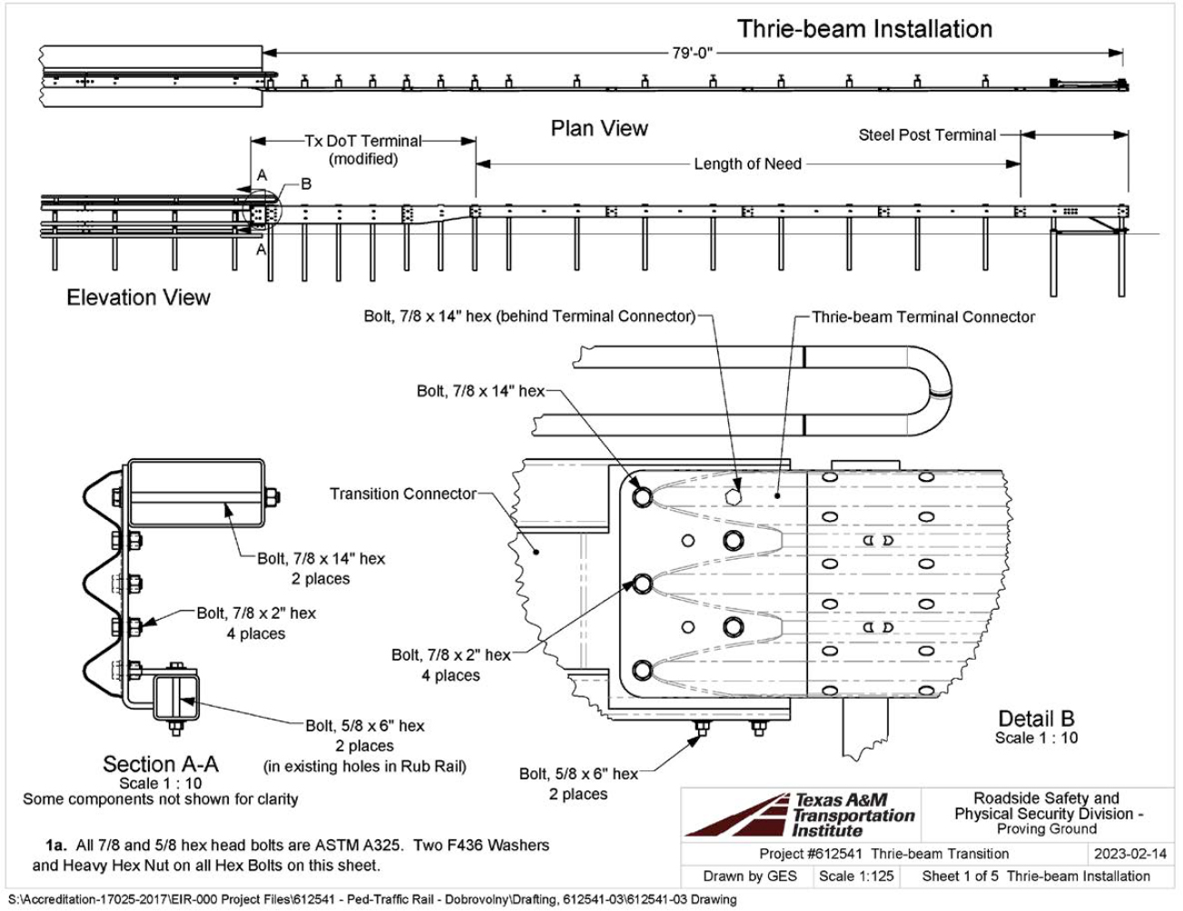

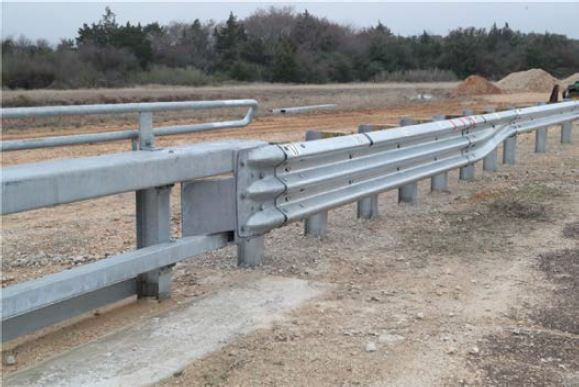
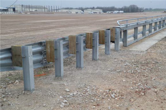
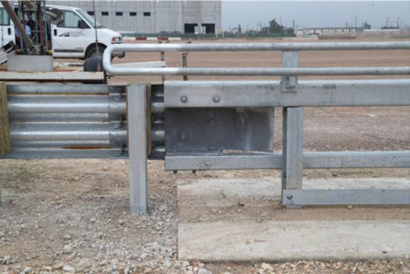
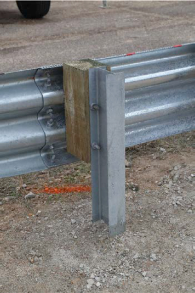
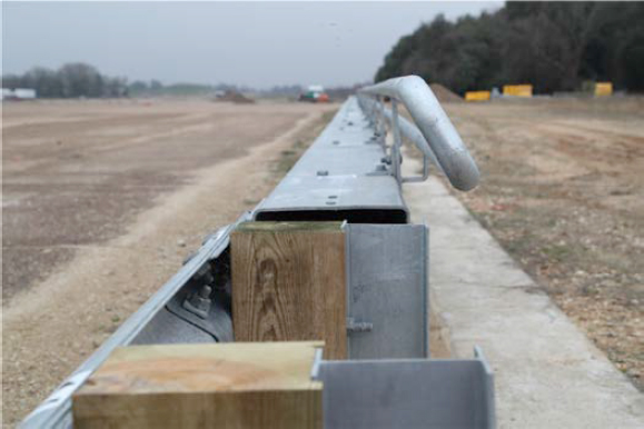
Figure 130 presents the overall information on the multifunctional barrier transition for Crash Test 612541-01-4, and Figures 131 through 134 provide photographs of the installation. Appendix E provides further details on the multifunctional barrier transition for Crash Test 612541-01-4. Drawings were provided by the TTI Proving Ground, and construction was performed by TTI Proving Ground personnel.
Design Modifications During Tests
No modifications were made during testing.
Material Specifications
Appendix I provides material certification documents for the materials used to install/construct the multifunctional barrier transition. For information on the concrete, see Table 47.
Soil Conditions
The test installation was installed in standard soil meeting Type 1 Grade D of AASHTO standard specification M147-17 “Materials for Aggregate and Soil Aggregate Subbase, Base, and Surface Courses.” In accordance with Appendix B of MASH, the soil strength was measured the day of the crash test. During installation of the pedestrian traffic rail transition for full-scale crash testing, two 6-ft-long W6 × 16 posts were installed in the immediate vicinity of the pedestrian traffic rail transition with the same fill materials and installation procedures used in the test installation and the standard dynamic test. Table B.1 in MASH Appendix B (1) presents minimum soil strength properties established through the dynamic testing performed in accordance with MASH Appendix B.
The minimum post loads are shown in Table 82 and Table 83. Table 82 shows the loads on the post at the specified deflections on the day of MASH Test 3-21, February 15, 2023. The backfill material in which the multifunctional barrier transition was installed met the minimum MASH requirements for soil strength. Table 83 shows the loads on the post at the specified deflections on the day of MASH Test 3-20, March 1, 2023. The backfill material in which the multifunctional barrier transition was installed met the minimum MASH requirements for soil strength.
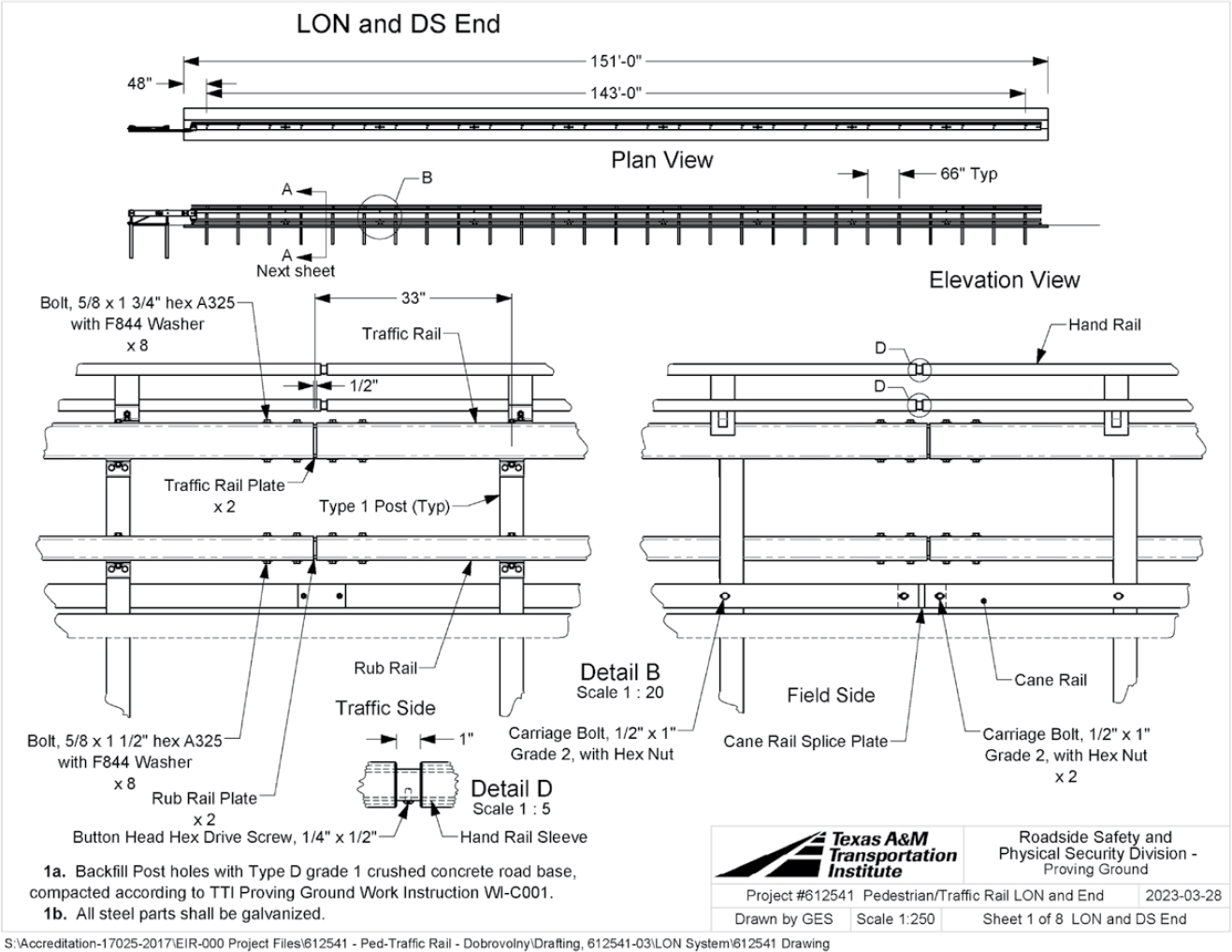
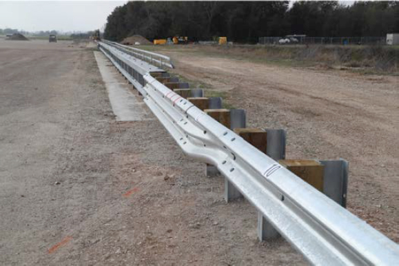
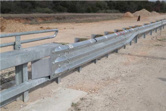
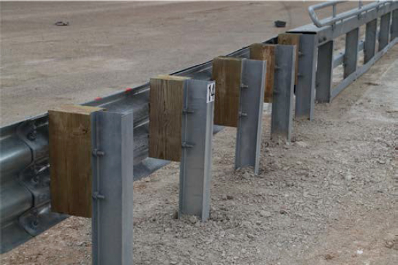

Table 82. Soil strength for Crash Test 612541-01-3.
| Displacement (in.) | Minimum Load (lb) | Actual Load (lb) |
|---|---|---|
| 5 | 4,420 | 7,515 |
| 10 | 4,981 | 8,454 |
| 15 | 5,282 | 8,878 |
Table 83. Soil strength for Crash Test 612541-01-4.
| Displacement (in.) | Minimum Load (lb) | Actual Load (lb) |
|---|---|---|
| 5 | 4,420 | 8,757 |
| 10 | 4,981 | 10,363 |
| 15 | 5,282 | 10,999 |


