Development of a MASH Barrier to Shield Pedestrians, Bicyclists, and Other Vulnerable Users from Motor Vehicles (2024)
Chapter: 7 System Details for MASH 3-10 and 3-11 Tests

CHAPTER 7
System Details for MASH 3-10 and 3-11 Tests
Test Article and Installation Details
The length of the test installation was 185 ft 7½ in. and consisted of a traffic rail and rub rail on the traffic side and pedestrian rails on the field side. Each end of the installation was anchored with a steel post W-beam cable anchorage system that was approximately 9 ft 4 in. long. The traffic rail was constructed of an HSS with dimensions of 12 × 6 × ¼ in. with its top located 32 in. above grade. The rub rail was an HSS with dimensions of 4 × 4 × ¼ in. with its top located 13 in. above grade. The rails were supported by W6 × 8.5 posts spaced at 66 in. on center.
Two field side handrails were fabricated of HSS tubing 1.90 in. in diameter by 0.145 in. thick. Their centers were located 35 in. and 41 in. above grade. A cane rail, also on the field side, was fabricated of 11 gauge 4-in.-wide plate with its bottom edge 1 in. above grade.
The posts were set in a 19-in.-wide, 4-in.-thick continuous area of low-strength grout with 24-in.-wide, 4-in.-thick concrete slabs on both sides. The traffic side faces of the posts were 4 in. from the joint between the concrete and grout.
Figure 73 presents overall information on the multifunctional barrier, and Figure 74 provides photographs of the installation. Appendix B provides further details on the multifunctional rail. Drawings were provided by the TTI Proving Ground, and construction was performed by MBC Management and supervised by TTI Proving Ground personnel.
Design Modifications During Tests
No modifications were made to the installation during the testing phase.
Material Specifications
Appendix I provides material certification documents for the materials used to install and construct the multifunctional barrier. Table 47 shows the average compressive strength of the concrete.
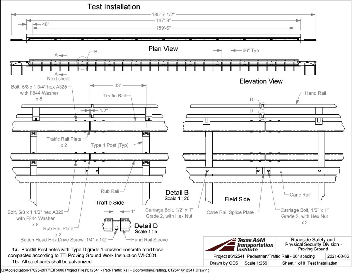
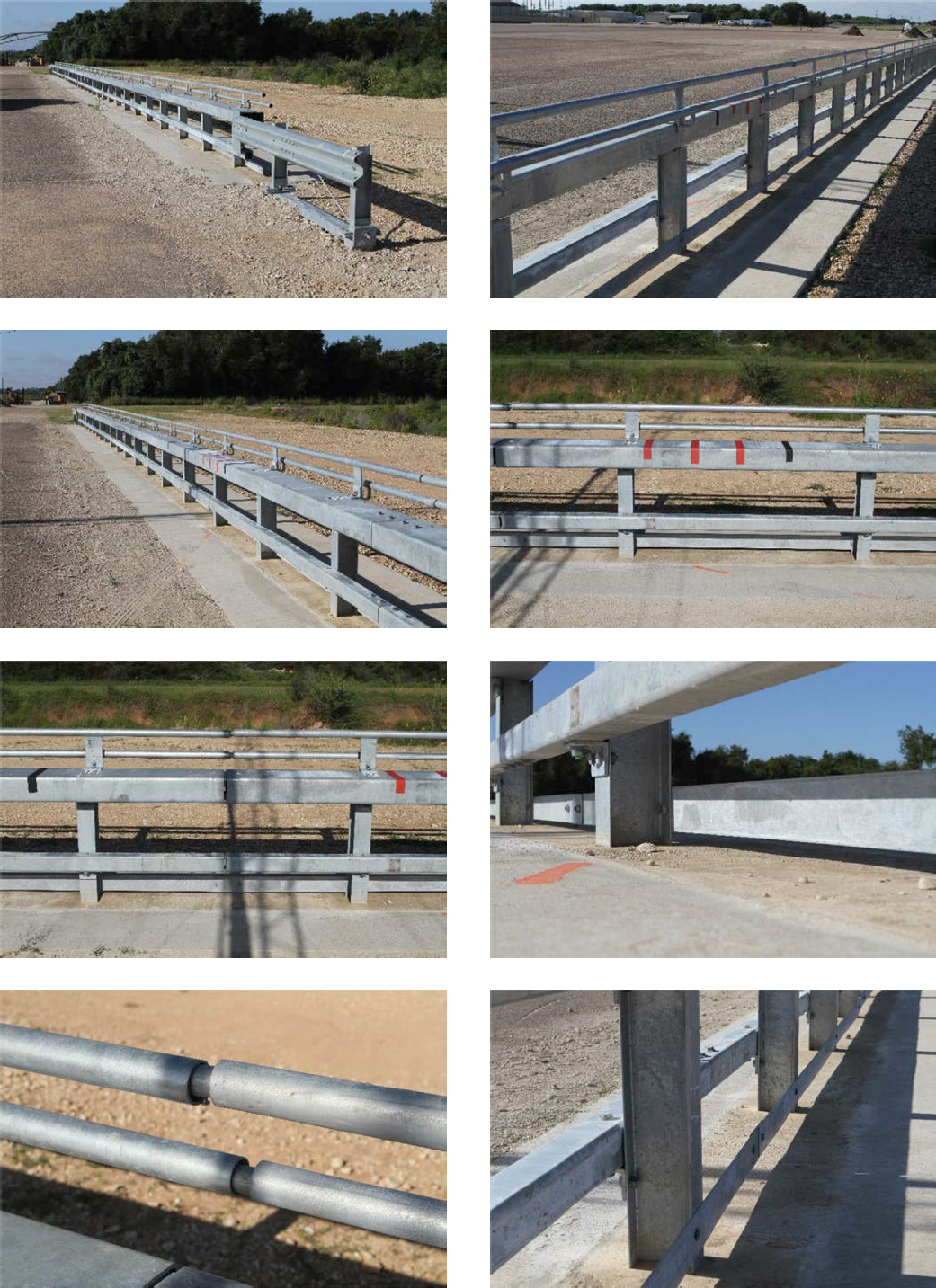
Table 47. Concrete strength.
| Location | Design Strength (psi) | Average Strength (psi) | Age (days) | Detailed Location |
|---|---|---|---|---|
| Concrete | 2,000 | 5,030 | 77 | Traffic and field side concrete |
| Grout | 100–220 | 170 | 21 | All grout for first test |
| Grout | 100–220 | 160 | 17 | Grout for Posts 15 through 20 for second test |
Soil Conditions
The test installation was installed in standard soil meeting Type 1 Grade D of AASHTO standard specification M147-17 “Materials for Aggregate and Soil Aggregate Subbase, Base, and Surface Courses.” In accordance with Appendix B of MASH, the soil strength was measured the day of the crash test. During installation of the multifunctional barrier for full-scale crash testing, two 6-ft-long W6 × 16 posts were installed in the immediate vicinity of the multifunctional barrier with the same fill materials and installation procedures used in the test installation and the standard dynamic test. Table I.1 in Appendix I presents minimum soil strength properties established through the dynamic testing performed in accordance with MASH Appendix B.
The minimum post loads are shown in Table 48 and Table 49. Table 48 shows the loads on the posts at the specified deflections on the day of Test 3-10, September 14, 2021. The backfill material in which the multifunctional barrier was installed met the minimum MASH requirements for soil strength. Table 49 shows the loads on the posts at the specified deflections on the day of Test 3-11, August 24, 2021. The backfill material in which the multifunctional barrier was installed met the minimum MASH requirements for soil strength.
Table 48. Soil strength for Test 3-10 (Test 612541-01-2).
| Displacement (in.) | Post Load (lb) | |
|---|---|---|
| Minimum | Actual | |
| 5 | 4,420 | 10,575 |
| 10 | 4,981 | 11,090 |
| 15 | 5,282 | 10,454 |
Table 49. Soil strength for Test 3-11 (Test 612541-01-1).
| Displacement (in.) | Post Load (lb) | |
|---|---|---|
| Minimum | Actual | |
| 5 | 4,420 | 7,484 |
| 10 | 4,981 | 8,212 |
| 15 | 5,282 | 8,424 |


