Development of a MASH Barrier to Shield Pedestrians, Bicyclists, and Other Vulnerable Users from Motor Vehicles (2024)
Chapter: 4 Preliminary Design Options

CHAPTER 4
Preliminary Design Options
The research team reviewed the information presented in the previous chapters and developed several design options addressing the needs of this research study to present to the NCHRP project panel for consideration. The proposed options were designed to address and balance system needs from the perspectives of both vehicular impact performance and pedestrian/bicyclist accessibility while minimizing material cost and installation complexity. The research team developed the proposed design options with the objective of meeting the relevant standards and guidelines, such as AASHTO’s MASH (1) and Roadside Design Guide (31) and PROWAG (3). Design elements identified in the previous tasks, such as barrier height and implementation of PROWAG criteria, were highlighted for each proposed barrier option.
The research team also addressed basic requirements for the barrier systems, including accommodation of service loads to meet impact performance requirements, while providing other desirable functional characteristics. As an example, the research team took into consideration placement and attachment of barrier design elements to increase the safety of vulnerable users while still optimizing vehicular driver safety during an impact.
The design concepts were not presented as yet fully engineered and detailed at this stage but were sufficient for initial assessment of the feasibility of rail behavior and capability. The research team documented the anticipated advantages and disadvantages of each design alternative, including any perceived performance benefits and application limitations.
The proposed options were as follows:
- Option A: Steel-only open rail system with longitudinal hollow structural section (HSS).
- Option B: Steel-only open rail system with longitudinal HSS and metal mesh.
- Option C: W-beam guardrail system with rails.
- Option D: W-beam guardrail system with metal mesh.
- Option E: Steel-only open rail system with covering HSS top rail.
- Option F: Steel-only open rail system with covering HSS top rail and metal mesh.
Design of Multifunctional Barrier Components
TTI researchers developed a preliminary design of the components of the guardrail system meant to address vulnerable user concerns. This included a pedestrian handrail, a bicycle handrail, and a cane detection rail. The preliminary design of these components was then incorporated into a further analysis and computer simulation efforts.
To design the multifunctional rail, the TTI researchers followed the design guidelines described by ADA standards and AASHTO specifications (2). Because of the lack of guidance with regard to the structural design of bicycle handrails, the research team employed the same
design loads and methodology used for the pedestrian rail. The preliminary design of the pedestrian handrail consisted of two components: the geometric concerns and the structural concerns. The geometric concerns consisted of items such as the diameter of the handrails and the spacing of the vertical supports. The structural concerns involved the flexural capacity of the rails and the combination loads resisted in the vertical supports. Some overlap did exist between these two concerns, for example, the diameter of the round steel tubes affecting the flexural capacity of the handrail.
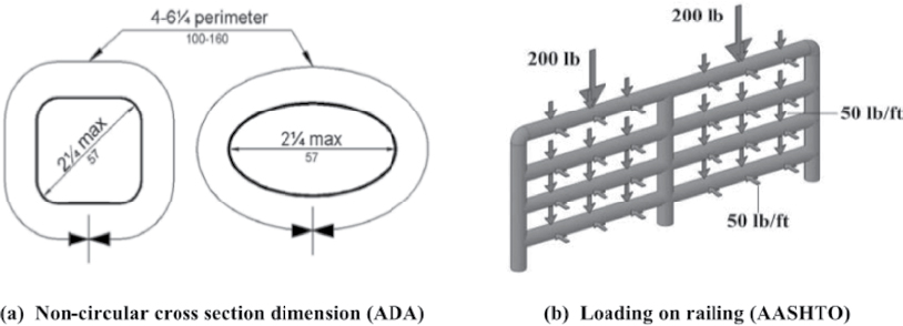
The selection of the outer diameter of the handrails was based on the requirements set forth by ADA standards (Figure 23a). The design loads on the handrails were according to AASHTO specifications (Figure 23b). The wall thickness of the handrails was chosen on the basis of the flexural capacity of the HSS member. The section of this handrail size was also based on material availability. The vertical support was designed for both axial load and combined axial-flexural loading arising from the horizontal offset between the handrails and the vertical supports. The vertical supports were spaced to match the spacing of a standard quarter-post spacing guardrail system. This quarter-post spacing was desired because of its reduced dynamic deflection compared with standard guardrail spacing.
The size of the cane detection rail was based on material availability, cost effectiveness, and crashworthiness. This design was further evaluated during the computer simulation effort.
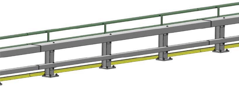
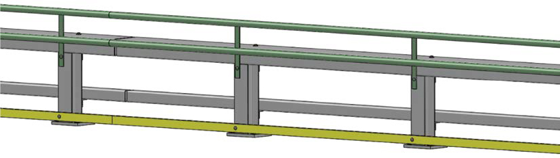
Option A: Steel-Only Open Rail System with Longitudinal HSS
Option A was a steel-only open rail system bolted to a concrete slab. The total height of the railing system was 42 in., which included a post height of 32 in. and an additional bicycle railing to reach the required 42 in. The bolted connection between the post and the concrete slab could be located on the side of the post aligned with the longitudinal deployment of the system to prevent interference with the shared-use path.
The proposed option utilized 30-in.-long steel posts, which could be either a wide flange or an HSS section. The anticipated post spacing was approximately 10 ft; however, detailed engineering analysis would be required to define post spacing on the basis of the system characteristics. Depending on the post option (i.e., wide flange or HSS), different types of connections could be used. Steel angles were suggested for attachment of the horizontal HSS railing to the post. A steel plate could be included in the design to cover the steel post top, providing an element of protection in case of direct contact between the vulnerable user and the sharper edges along the
top of the post. The Option A design did not include continuous protection along the back side of the railing. Consequently, Option A still resulted in considerable post exposure to vulnerable users. If the post were designed to be an HSS member, however, the post would not present significant exposed edges.
The barrier included a total of three horizontal steel HSS railings. The horizontal railings would be adequately spaced to limit snagging potential during vehicular impact. Furthermore, the lower railing would be required to prevent any vehicle underriding.
Option A included two additional preferred design elements: a handrail for pedestrians and a lower rail for cane detection. Both the bicycle and the pedestrian rails had a 2-in. diameter to comply with AASHTO requirements and were adequately spaced away from the posts to allow for hand gripping. Both rails were connected to a plate that could be bolted to the back side of the post. The lower small rail (for cane detectors) was connected to the back of the posts and positioned a few inches above the ground surface to allow for water drainage.
Option A could be designed to significantly limit deflections of the system during vehicular impact events. However, these details would significantly increase the cost for construction of the system. All of the material proposed for the construction of Option A was expected to be readily available.
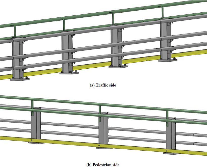
Table 29 summarizes anticipated advantages and disadvantages of the Option A barrier system. Figure 24 illustrates a perpendicular view of Option A, and Figure 25 shows a three-dimensional rendering of Option A from the traffic and pedestrian sides.
Option B: Steel-Only Open Rail System with Longitudinal HSS and Metal Mesh
Option B was a steel-only open rail system bolted to a concrete slab. The main difference between Option A and Option B was that Option B included a metal mesh at the back of the rail system on the vulnerable users’ side. The metal mesh was connected to the bicycle railing plate and extended to the lower cane detector rail. The metal sheet would need to be constructed with a mesh size to prevent any snagging of vulnerable users with the system in the event of accidental fall or impact. Option B is depicted in Figure 26 as a system without a pedestrian handrail. However, a pedestrian handrail could be incorporated in the proposed system design if desired.
The total height of the railing system was 42 in., which included a post height of 32 in. and an additional bicycle railing to reach the required 42 in. The bolted connection between the post and the concrete slab could be located on the side of the post along the longitudinal deployment of the system to prevent interference with the shared-use path.
Table 29. Option A barrier system: Perceived advantages and disadvantages.
| Advantages | Disadvantages |
|---|---|
|
|

The proposed option utilized 30-in.-long steel posts, which could be either a wide flange or an HSS section. Because this design included continuous protection along the back side of the railing (proposed metal sheet), Option B does not result in post exposure to vulnerable users. Utilization of wide flange steel posts, therefore, would not present an exposed edge problem, given that the vulnerable users would be shielded from the entire post by the metal sheet protection system. Therefore, an HSS section would not be required to prevent interaction of vulnerable users with exposed edges. The anticipated post spacing was approximately 10 ft; however, detailed engineering analysis would be required to define post spacing on the basis of the system characteristics.
Steel angles were suggested for attachment of the horizontal HSS railing to the post. A steel plate could be included in the design to cover the steel post top, providing an element of protection in case of direct contact between the vulnerable user and the sharper edges along the top of the post.
The barrier included a total of three horizontal steel HSS railings. The horizontal railings would be adequately spaced to limit snagging potential in case of vehicular impact. Furthermore, the lower railing would be required to prevent any vehicle underriding.
Option B included a lower rail for cane detection, which was connected to the back of the posts and positioned a few inches from the ground surface. This setup would allow water drainage through the barrier system.
Option B could be designed to significantly limit deflections of the system during vehicular impact events. However, these details would significantly increase the cost for the system construction. All of the material proposed for construction of Option B was expected to be readily available.
With inclusion of the metal sheet, Option B represented a more challenging system with regard to snow clearing. In addition, aesthetic considerations and visibility through the barrier option would be compromised because of the presence of the metal mesh.
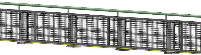
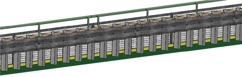
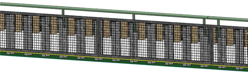
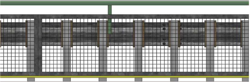
Table 30 summarizes the anticipated advantages and disadvantages of the Option B barrier system. Figure 27 illustrates a perpendicular view of Option B, and Figure 28 shows a rendering of Option B from the traffic and pedestrian sides. Figure 29 shows an elevation view from the pedestrian side.
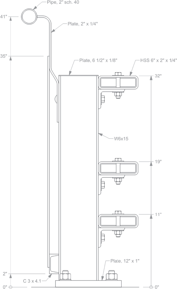
Table 30. Option B barrier system: Perceived advantages and disadvantages.
| Advantages | Disadvantages |
|---|---|
|
|


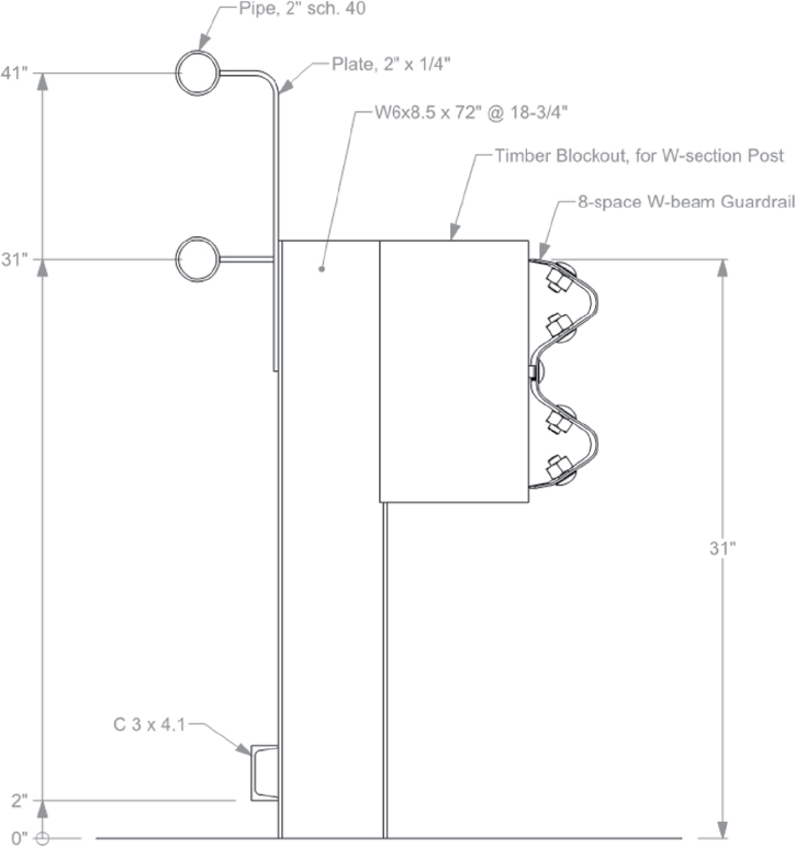
Option C: W-Beam Guardrail System with Rails
Option C was a steel post, wood blockout W-beam rail system embedded in soil and surrounded by a low-strength grout to minimize vegetation maintenance. The total height of the railing system was 42 in., which included a post height of 32 in. and an additional bicycle railing to reach the required 42 in.
The proposed option utilized a commonly available wide flange 72-in.-long steel post. The anticipated post spacing, based on previous research completed by the research team, was 18¾ in. Previous testing on a steel post W-beam guardrail system with 18¾-in. post spacing showed the lateral deflection during vehicular impact (i.e., deflection into the shared-use path) to be approximately 20 in. The Option C design did not include a continuous protection system along the back side of the railing. Consequently, Option C still resulted in considerable post exposure as well as edges exposed to vulnerable users.
Option C included two additional preferred design elements: a handrail for pedestrians and a lower rail for cane detection. Both bicycle and pedestrian rails had a 2-in. diameter to comply with AASHTO requirements and were adequately spaced away from the posts to allow for hand gripping. Both rails were connected to a plate that could be bolted to the back side of the post. The lower small rail (for cane detectors) was connected to the back of the posts and positioned a few inches above the ground surface to allow for water drainage.
All material proposed for construction of Option C was expected to be readily available, and the construction cost was estimated to be comparable to that of a commonly deployed 31-in. W-beam guardrail embedded in soil and surrounded by a low-strength grout.
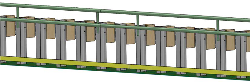
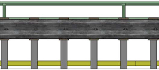
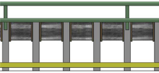
Table 31 summarizes the anticipated advantages and disadvantages of the Option C barrier system. Figure 30 illustrates a perpendicular view of Option C, and Figure 31 and Figure 32 show a rendering of Option C from the traffic and pedestrian sides, respectively. Figure 33 and Figure 34 show an elevation view from the pedestrian and traffic sides, respectively.
Option D: W-Beam Guardrail System with Metal Mesh
Option D was a steel post, wood blockout W-beam rail system embedded in soil and surrounded by a low-strength grout to minimize vegetation maintenance. The total height of the railing system was 42 in., which includes a post height of 32 in. and an additional bicycle railing to reach the required 42 in.
The proposed option utilized a commonly available wide flange 72-in.-long steel post. The anticipated post spacing, based on previous research and testing studies, was 18¾ in. Previous testing on a steel post W-beam guardrail system with 18¾-in. post spacing showed the lateral deflection during vehicular impact (i.e., deflection into the shared-use path) to be approximately 20 in.
Table 31. Option C barrier system: Perceived advantages and disadvantages.
| Advantages | Disadvantages |
|---|---|
|
|

The Option D design included a continuous protection system along the length of the back side of the railing. The metal mesh was connected to the bicycle railing plate and extended to the lower cane detector rail. The metal sheet would need to be constructed with a mesh size that would prevent any snagging of vulnerable users with the system in the event of accidental fall or impact. Option D was a system without a pedestrian handrail. However, a pedestrian handrail could be incorporated in the proposed system design if desired.
Option D included a lower rail for cane detection. The lower small rail (for cane detectors) was connected to the back of the posts and positioned a few inches from the ground surface to still allow for proper drainage.
The material proposed for the construction of Option D was expected to be readily available.
Table 32. Option D barrier system: Perceived advantages and disadvantages.
| Advantages | Disadvantages |
|---|---|
|
|
Table 32 summarizes the anticipated advantages and disadvantages of the Option D barrier system. Figure 35 illustrates a perpendicular view of Option D, and Figure 36 and Figure 37 show a rendering of Option D from the traffic and pedestrian sides, respectively. Figure 38 shows an elevation view from the pedestrian side.
With inclusion of the metal mesh, Option D represented a more challenging system with regard to snow clearing. In addition, aesthetic considerations and visibility through the barrier option would be compromised, because of the presence of the metal mesh covering most of the railing portion.

Option E: Steel-Only Open Rail System with Covering HSS Top Rail
Option E was a steel-only open rail system bolted to a concrete slab. The total height of the railing system was 42 in., which included a post height of 32 in. and an additional bicycle railing to reach the required 42 in. The bolted connection between the post and the concrete slab could be located on the side of the post aligned with the longitudinal deployment of the system to prevent interference with the shared-use path.
The proposed option utilized steel posts approximately 24 in. long, which could be either a wide flange or an HSS section. The anticipated post spacing was approximately 10 ft; however, detailed engineering analysis would be required to define post spacing on the basis of the system characteristics. A 6-in.-tall longitudinal HSS railing element was placed on top of the steel posts and connected to them with steel angles. The 6-in.-tall longitudinal railing provided adequate barrier strength to vehicular impacts while providing continuous top post protection in case of direct contact with the sharper edges on the top of the post by the vulnerable user.
The Option E design did not include a continuous protection system along the length of the back side of the railing. Consequently, Option E still resulted in considerable post exposure as well as edges exposed to vulnerable users. However, were the post designed to be an HSS section, it would not present significant exposed edges.
Option E was proposed with inclusion of an additional horizontal steel HSS railing. The horizontal railing would be needed, properly located along the height of the system, to limit snagging potential in case of vehicular impact.
Option E included two additional preferred design elements: a lower rail for cane detection and a handrail for pedestrians, as depicted in Figure 39. Both bicycle and pedestrian rails had a 2-in. diameter to comply with AASHTO requirements and were adequately spaced from the posts’ back side to allow for easy hand gripping. Both rails were connected to a plate that could be bolted to the posts’ back side. The lower small rail (for cane detectors) was connected to the back of the posts and positioned a few inches above the ground surface to allow for proper drainage.
Option E could be designed to significantly limit deflections of the system during vehicular impact events; these details, however, might increase the cost for the system construction significantly. The material proposed for construction of Option E was anticipated to be readily available.
Table 33 summarizes the anticipated advantages and disadvantages of the Option E barrier system. Figure 39 illustrates a perpendicular view of Option E, and Figure 40 and Figure 41 show a rendering of Option E from the traffic and pedestrian sides, respectively.
Option F: Steel-Only Open Rail System with Covering HSS Top Rail and Metal Mesh
Option F was a steel-only open rail system bolted to a concrete slab. The total height of the railing system was 42 in., which included a post height of 32 in. and an additional bicycle railing to reach the required 42 in. The bolted connection between the post and the concrete slab could be located on the side of the post along the deployment of the system to prevent interference with the shared-use path.
The proposed option utilized steel posts approximately 24 in. long, which could be either a wide flange or an HSS type. The anticipated post spacing was approximately 10 ft; however, detailed engineering analysis would be required to define post spacing on the basis of the system
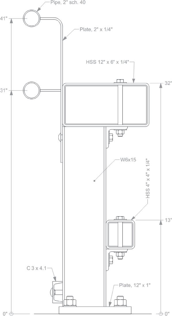
Table 33. Option E barrier system: Perceived advantages and disadvantages.
| Advantages | Disadvantages |
|---|---|
|
|
characteristics. A 6-in.-tall longitudinal HSS railing element was placed on top of the steel posts and connected to them through steel angle. The 6-in.-tall longitudinal railing served as a steel beam element, offering adequate barrier strength to vehicular impacts and, at the same time, providing continuous top post protection against direct contact by the vulnerable user with the sharp edges on the top of the post.
The Option F design included a continuous protection system along the length of the back side of the railing. The metal mesh was connected to the bicycle railing plate and extended to the lower cane detector rail. The metal sheet would need to be constructed with a mesh size that would prevent any snagging of vulnerable users with the system in the event of accidental fall or impact. Option F is depicted in Figure 42 as a system without a pedestrian handrail. However, a pedestrian handrail could be incorporated in the proposed system design if desired.
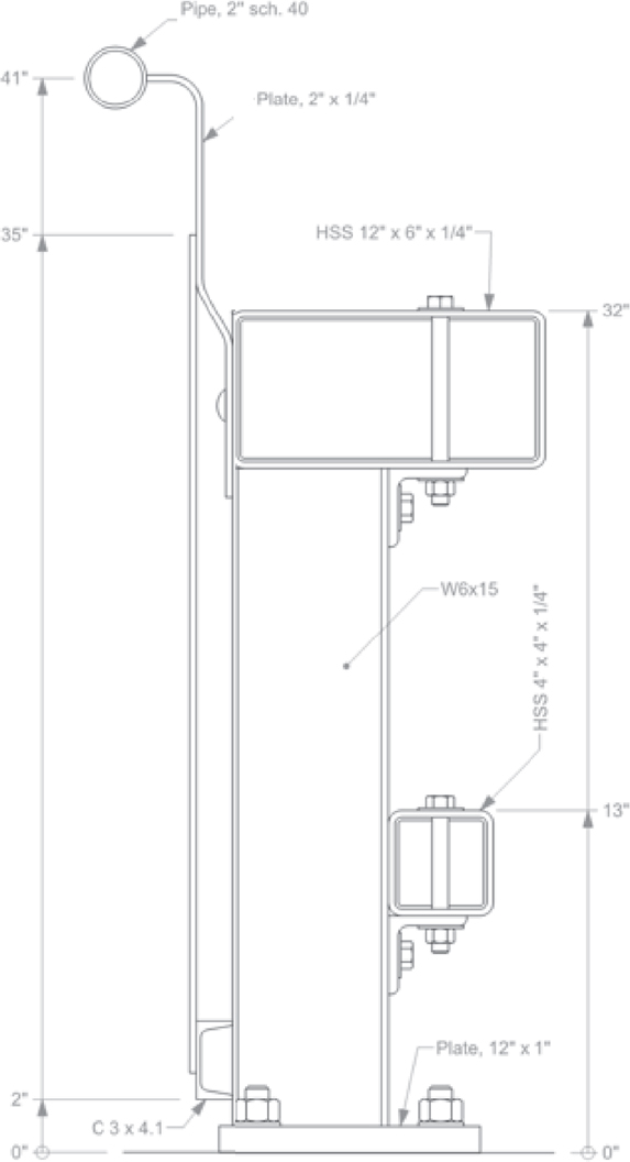
Table 34. Option F barrier system: Perceived advantages and disadvantages.
| Advantages | Disadvantages |
|---|---|
|
|
Option F was proposed with inclusion of an additional horizontal steel HSS railing. The horizontal railing would be needed, properly located along the height of the system, to limit snagging potential in case of vehicular impact.
Option F included two preferred additional design elements: a lower rail for cane detection and a handrail for pedestrians, as shown in Figure 42. The lower small rail (for cane detectors) was connected to the back of the posts and positioned a few inches from the ground surface to allow for proper drainage.
Option F could be designed to significantly limit deflections of the system during vehicular impact events; these details, however, might increase the cost for the system construction significantly. The material proposed for construction of Option F was expected to be readily available.
Table 34 summarizes the anticipated advantages and disadvantages of the Option F barrier system, and Figure 42 illustrates a perpendicular view of the system. With inclusion of the metal mesh, Option F represented a more challenging system with regard to snow clearing. In addition, aesthetic considerations and visibility through the barrier option would be compromised because of the presence of the metal mesh covering most of the railing portion.
Design Comparison
Table 35 summarizes the six different options reported in this chapter. The research team compared the perceived advantages and disadvantages for each proposed option. To help compare the proposed system designs in an objective manner, the research team suggested a rating for each of the proposed systems based on the anticipated advantages and disadvantages. A rating of one, two, or three stars for each element considered during the barrier design process was suggested. Three stars indicates a barrier concept better addresses that design aspect than a barrier concept that has one star for that design aspect. For example, installed cost of Option C is significantly lower in comparison to some of the other design options. Thus, Option C was assigned three stars for installation cost and other design concepts (e.g., Option A) received only one star for installation cost.
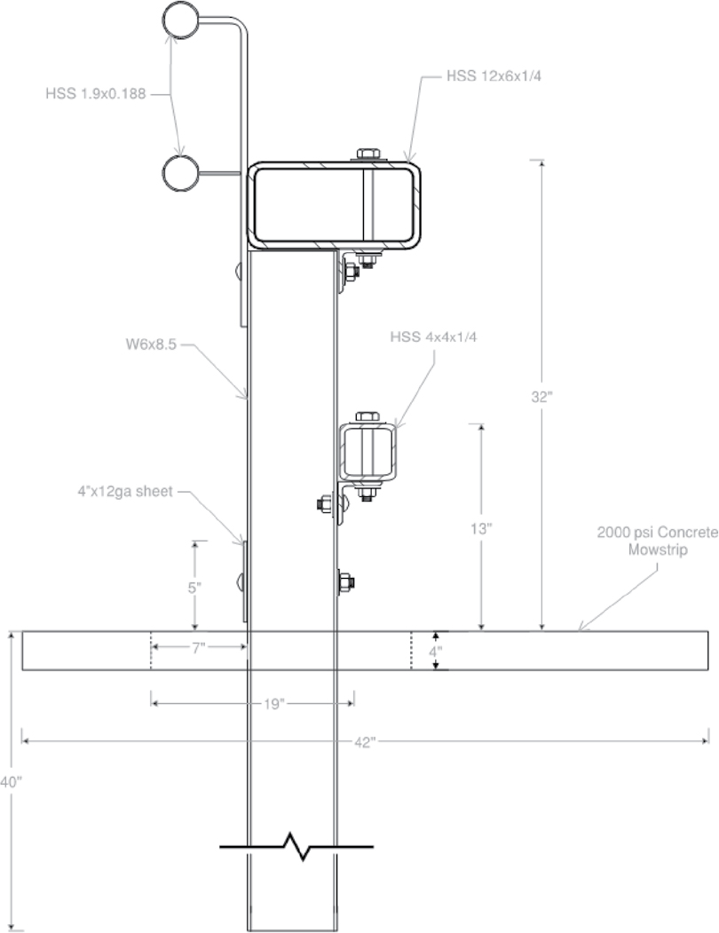
Design Recommendation and Modification
The preliminary designs for the pedestrian and bicycle handrails and the cane detection rail are shown in Figure 43. This is a variation of Option E derived from discussion with the project panel. Although some of the original concepts included a base-plated post bolted to a concrete slab or pavement, the project panel selected a direct embedded post option. Direct post embedment reduces cost by eliminating the need for a structural slab for mounting of the barrier. It was further decided that vegetation control should be incorporated around the barrier system. This consisted of a concrete mow strip on both the traffic and field sides of the barrier and an interior soil strip into which the barrier posts are embedded. The top 4 in. of this soil strip,
Table 35. System option comparison.
| Rating | Option A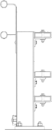 |
Option B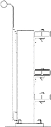 |
Option C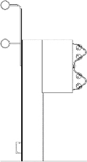 |
Option D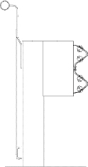 |
Option E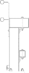 |
Option F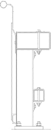 |
|---|---|---|---|---|---|---|
| Visibility, aesthetics, deflection, drainage, material availability, exposed edges (HSS), snow clearing | Deflection, drainage, material availability, continuous protection, post exposure, exposed edges | Material availability, installed cost | Material availability, continuous protection, post exposure, exposed edges | Visibility, deflection, drainage, material availability, exposed edges (HSS), aesthetics, snow clearing, continuous protection (post top only) | Deflection, material availability, exposed edges, post exposure, continuous protection | |
| Post exposure | Visibility, aesthetics | Drainage, aesthetics, post exposure, snow clearing, visibility | Drainage, installed cost | Continuous protection (post body only), post exposure | Visibility, aesthetics, drainage | |
| Installed cost, continuous protection, exposed edges (wide flange) | Installed cost, snow clearing | Deflection, exposed edges | Aesthetics, visibility, deflection, snow clearing | Installed cost | Installed cost, snow clearing |
corresponding to the thickness of the mow strip, were filled with a low-strength grout to provide vegetation control around the posts. The cane detection rail on the bottom field side of the barrier was changed from a structural channel to a steel plate, which reduced its projection from the post and its cost. This preliminary design was subject to change pending further analysis and computer simulation.
This section provides information about preliminary drawings with proposed changes to the design after several simulation iterations were performed. After considering several design options, the research team decided to provide post spacing of 22 in., 44 in., and 66 in. for performance of further simulations to choose a final option for testing. The models were checked for deformation and economic feasibility.
Some modifications in design to optimize the overall system were as follows:
- Post spacing was increased to 22 in., 44 in., and 66 in. to obtain economic options from the viewpoint of construction, production, and cost effectiveness.
- For the 22-in. post spacing options, the angle brackets used to connect the rails to the posts were at each post for the lower rub rail.
- The spliced box sections for both the rails were replaced with simple plate splices.
- The rub rail thickness was increased from ⅛ in. to ¼ in. after preliminary simulations indicated vehicle instability issues due to the light rub rail section.
- The handrail design was modified to further optimize it from the perspective of cost, fabrication, installation, and transportation.
The 44-in. post spacing design was similar to the 22-in.-tall design, except that the traffic side of the rub rail was extended to match the plane of the top traffic rail, as mentioned before.
When considering the simulation results obtained from the 22-in. and 44-in. post spacing, the researchers saw the opportunity to increase the post spacing and further optimize the design. The post spacing was increased to 66 in., and simulations were conducted to check the MASH limits along with the maximum deflection requirements. The research team terminated further investigation after the results for the 66-in. post spacing option were analyzed, since the deflection results were very close to the desired deflection limit of 24 in. proposed by the project panel in the kickoff meeting. The simulation results for this option are provided in the next chapter.


