Developing a Guide for Transit Traction Power Cables (2024)
Chapter: 4 Case Studies
Chapter 4. Case Studies
4.1. Case Study Structure
Based on the survey results, ten case studies were developed. Case studies were developed to demonstrate maintenance practices from a variety of systems (small, large, old, and new) by engaging industry subject matter experts experienced in the design, construction, maintenance, and operation of traction power systems. Interviews were carried out in the selected locations for the case studies. The case studies were carried out in Greater Cleveland (1), New Orleans (2), California Bay Area (3), New York (4-5), Oregon (6), Utah (7), Maryland (8), Washington (9), and Minneapolis-St.Paul (10). The selected case study states are given in Figure 4.1 and the Tables as listed below.
Case Study 1: Greater Cleveland Regional Transit Authority given at Table 4.1.
Case Study 2: New Orleans Regional Transit Authority given at Table 4.3.
Case Study 3: California Bay Area Rapid Transit given at Table 4.5.
Case Study 4: New York City Transit given at Table 4.15.
Case Study 5: New York Amtrak’s Replacement Case given at Table 4.16.
Case Study 6: Oregon Tri-County Metropolitan Transportation District, given at Table 4.18.
Case Study 7: Utah Transit System given at Table 4.25.
Case Study 8: Maryland given at Table 4.26.
Case Study 9: Washington Metropolitan Area Transit Authority given at Table 4.27.
Case Study 10: Minneapolis-St.Paul Transit System given at Table 4.28.
4.2. Case Study 1: Greater Cleveland Regional Transit Authority
Table 4.1. Greater Cleveland Regional Transit Authority
| ||||||||||||||||||
| Concept | Current Practice | |||||||||||||||||
| Quick view | A weekly riding visual inspection is performed in which maintenance workers observe the OCS for defects. A 6-month walking inspection is performed in the fall and spring where maintenance workers can work at a slower pace visually inspecting for defects from the ground. Defects noted during either inspection are then inspected hands-on and repaired as soon as possible by a secondary crew. There is also a hands-on inspection performed on a piece of work equipment with an elevated platform so the crews can physically touch and inspect the OCS. Bolted connections and overhead equipment such as section insulators, pullovers, splices, and feeder cables are inspected during this annual preventative maintenance task. Manhole inspections are performed every six months, and routinely check manholes in between inspections to pump potential water from the holes. The manholes are one of the most significant issues because of their locations. Many are in or near parking lots and roadways and we have seen issues with roadway salt during winter months. | |||||||||||||||||
| Summary | Degree of Degradation | They determine the degradation and condition of our feeder cable through routine maintenance. They inspect the overall appearance of the cable and its bolted electrical connections. They look for signs of weathering, fire or heat damage and cuts/tears in the jacket which may have been caused by accidents of damage from falling tree limbs. These inspections have various intervals ranging from every six months for routine visual inspections to a more in-depth hands-on inspection annually. In the manholes mentioned above, they look for indications of failure by heat in the manhole, steam coming from potential water. They look at the water to observe its color (green could indicate failure) and observe the cable for degradation. | ||||||||||||||||
| Diagnostic Indicators | They do not perform diagnostic testing on the feeder cable. The recommendation from APTA is specific for cables in conduit, duct back and troughs which may be susceptible to rodents or degradation due to moisture and electrolysis. The insulation resistance testing is also only recommended when the integrity of the cable is suspect. The current inspection and maintenance schedule is adequate to inspect the feeder cable promptly to observe any potential issues and damage to the existing cable on our property. | |||||||||||||||||
4.3. Case Study 2: New Orleans Regional Transit Authority
Table 4.2. New Orleans Regional Transit Authority
| ||||||||||||||||||||||||||
| Concept | Current Practice | |||||||||||||||||||||||||
| Quick view | The traction power personnel perform complex and specialized troubleshooting, preventative and corrective maintenance, and overhauls of traction power substation and overhead contact system and their associated sub-systems. The traction power maintenance team is responsible for assuring that all equipment is working and aligned properly to prevent damage to system and rail vehicles. They will also provide emergency response and will be called upon to support other areas regarding light rail service, special events, streetcar, and public safety and service. | |||||||||||||||||||||||||
| Summary | Degree of Degradation | There is no procedure to determine the degree of degradation. The cables are checked physically in a certain period. The majority of the cables are under the water and that makes such determination procedure difficult. | ||||||||||||||||||||||||
| Diagnostic Indicators | They are checking the substations. If there is a heat increase in the substation, this is an indicator for the maintenance crew. They do not have time to stop the operation for regular check-up. Therefore, they check the substation regularly. They have visual inspection manholes, and taps. | |||||||||||||||||||||||||
| Effecting Factors | For overheads, trees are the main environmental factors for them. They create some problems in case of extreme weather conditions. The other main problem is that the city is under the water making cables under the water in their service life. Over time, it penetrates. | |||||||||||||||||||||||||
| Replacement Strategies | They created the cable jacket itself to increase the life cycle. They designed their own taps that helped them to prevent water from the taps. They placed the taps in PVC sealed cages. They use a specific type of taps for aluminum cables. | |||||||||||||||||||||||||
| Smart Replacement Strategy | They do not currently have a smart replacement strategy | |||||||||||||||||||||||||
4.4. Case Study 3: California Bay Area Rapid Transit
Table 4.3. California Bay Area Rapid Transit
| ||||||||||||||||||||||||||
| Concept | Current Practice | |||||||||||||||||||||||||
| Quick view | BART trains run on 100% electric power. 30-year life assets are 45 years old. 68 Traction Power Substations (TPSS) ‒ Over 700 high voltage circuit breakers and switchgears ‒ Over 1.5M linear feet of cabling. San Francisco and Transbay Tube are most fragile pieces of the system, which failed previously. BART does not have standby traction power capability. | |||||||||||||||||||||||||
| Summary | Degree of Degradation | They do not monitor. Regular failures of any type will begin a process to replace all such cables. | ||||||||||||||||||||||||
| Diagnostic Indicators | Hi-pot, meggering and thump test. There is no test run in regular base. They only test cables during no revenue. | |||||||||||||||||||||||||
| Effecting Factors | Our experience shows temperature has the most effect on our system. For BART system cable structure such as PIPE & PILC type have most effect, changing all to EPR is increasing the useful life. | |||||||||||||||||||||||||
| Replacement Strategies | Typically, if damaged, splicing with new cable if it’s EPR, otherwise replacing the whole section. Cost & duration depends on the size and location of the fault. | |||||||||||||||||||||||||
| Smart Replacement Strategy | They are implementing the new monitoring system. | |||||||||||||||||||||||||
4.5. Case Study 4: New York City Transit
Table 4.4. New York City Transit
| ||||||||||||||||||||||||||
| Concept | Current Practice | |||||||||||||||||||||||||
| Quick view | Installation Considerations: Cable Pulling, Cable Weight, Duct Fill Ratio, Ampacity, and Splicing | |||||||||||||||||||||||||
| Summary | Degree of Degradation | There is no cable monitoring =. no testing unless cables use temporarily disconnected and inactive for weeks. shielded cables used in some applications. | ||||||||||||||||||||||||
| Diagnostic Indicators | No tests are done regularly | |||||||||||||||||||||||||
| Effecting Factors | Operating temp freezing to above 100-degree Fahrenheit. wet or dry 625 volts circuit use. 2000 VDC insulation level, typically pulled in fiberglass from duct banks. | |||||||||||||||||||||||||
| Replacement Strategies | Repair would only be done in emergency cables. Cable would be replaced during scheduled maintenance. Historically some failures have been experienced because of mechanical damage. In 2010, NYCT decided to implement CBTC based Train Control & Signals. Prior to this trains operate 15-18 TPH 600VDC Electric Motor in series parallel mode. To implement this philosophy, NYCT bought new 143 train cars that use AC Induction Motors with IGBT Inverters & CBTC input for modulation & brakes. However, the substations which are roughly a mile apart & associated power 1000V DC positive and negative cables were not modernized as part of the capital program. The DC trains use roughly 5500 A to start and 2600A run, AC Trains use 8000A to start and 3000A to run. With CBTC, 30TPH can be run, making better use of right of way and reduced crowding on trains. Cost is the cables run very hot and experience more cable and substation overloads. | |||||||||||||||||||||||||
| Smart Replacement Strategy | There is no smart strategy | |||||||||||||||||||||||||
| Review and Update | Performance Criteria are set as Electrical characteristics, Thermal performance and Resistance to water ingression and moisture. | |||||||||||||||||||||||||
4.6. Case Study 5: New York Amtrak Replacement Case
Table 4.5. Replacement of New York Amtrak’s 12kV PILC Traction Power Cables
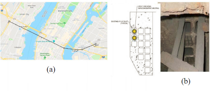
| Another case study was created based on Levi (2018) for replacement of Amtrak’s 12kV PILC traction power cables, a PILCs are considered to have the highest dielectric strength, lowest dissipation factor and lowest dielectric loss compared to both XLPE and EPR. XLPE performs better than EPR. PILC does not suffer from thermal expansion like EPR and XLPE, EPR has better overload tolerance than XLPE. Lead leakage from PILC cables is the main concern. PILC Lead Sheath is completely impermeable, Moisture ingress can occur at a rapid rate if the PILC sheath is damaged, EPR has better moisture resistance properties compared to XLPE. Figure 4.2 illustrates the Amtrak 12kV distribution for this case study. |
 |
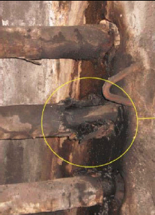
| PILC cables have been used since the late 1800s. They are resilient. Amtrak PILC cables have been used for nearly 90 years. The concerns are mainly a lack of splicer skills, and difficult to maintain. Underground cable design has evolved. Aging increases the probability of failure. PILC cable life is 44 years typically. The oldest installations are 70-90 years old; (mean age is 80 years). Current design life of EPR cables is predicted as 40 years (per study by EPRI). In Figure 4.3, a sample PILC cable failure is seen. Thermal failure, primarily due to moisture ingress, tends to increase insulation conductivity, which is approximately 40% of failure incidences. The electrical phenomenon is partial discharge, which is approximately 60% of failure incidences. |
 |
4.7. Case Study 6: Oregon Tri-County Metropolitan Transportation District of Oregon
Table 4.6. Oregon Tri-County Metropolitan Transportation District of Oregon
| ||||||||||||||||||||||||||
| Concept | Current Practice | |||||||||||||||||||||||||
| Quick view | They typically do a hard visual inspection on cables during the meggering process. Now they do a visual inspection on feeder cables inside the substation during annual track feeder breaker inspections. | |||||||||||||||||||||||||
| Summary | Degree of Degradation | Degradation has not been something they have been able to quantify. No cable monitoring systems in use. | ||||||||||||||||||||||||
| Diagnostic Indicators | In the past, they had been measuring insulation resistance by meggering, but results were varied, and failures occurred on supposedly good cables, so currently they are in a “run to fail” mode. | |||||||||||||||||||||||||
| Effecting Factors | Splices and taps subjected to seasonal water immersion in underground vaults | |||||||||||||||||||||||||
| Replacement Strategies | There is no replacement strategy. Only during the actual replacement work, which they try to do during non-revenue hours or in combination with other work outages. The failed cable can be taken out of service and operations can resume. | |||||||||||||||||||||||||
| Smart Replacement Strategy | Not existing | |||||||||||||||||||||||||
| Review and Update | Considerations in practice: Cable life, Cable failure modes, Installation considerations, Environmental issues, Manufacturability, and Cost | |||||||||||||||||||||||||
4.8. Case Study 7: Utah Transit System
Table 4.7. Utah Transit System
| |||||||||||||||||||||||||
| Concept | Current Practice | ||||||||||||||||||||||||
| Quick View | Positive Feeder Cable and Negative Rail Return Cable: Description: Power feeder cable and negative return cable shall be insulated, non-shielded, single copper conductor, suitable for wet or dry locations, with ethylene-propylene rubber insulation, 2000V, 900 C conductor temperature for normal operation, 1300 C for emergency operation and 2500 C for short circuit conditions, unshielded as indicated. Size of cables to be 500 kcmil, or as shown on the Contract Drawings. Conductors: Conductors for positive feeder cable and negative return cable shall be coated, soft drawn copper, complying with ASTM B3, covered with a double wrapped separator tape, or extruded semi-conducting EPR screen. Conductor Voltage Size Rating Stranding Material 500 kcmil 2000 Class C or D Copper. Insulation: Positive feeder cable and negative return cable shall be insulated with low-smoke, flame-retardant, ozone-resistant, ethylene-propylene rubber compound, complying with AREMA Signal Manual, Part 10.3.19 and ICEA S-95- 658, and rated for 900 C normal operating temperature and 1100C hot spot. This insulation thickness shall be as follows: Conductor Voltage Ethylene-Propylene Size Rating Rubber 500 kcmil 2000 90 mil Jacket: Low-smoke, flame-retardant, ozone-resistant, non-halogen, polyolefin thermosetting compound, meeting the flame test requirements of UL 1581 and ICEA T-30-520. Minimum jacket wall thickness shall be 65 mils. Color shall be black. If 500MCM messenger wire is used. Single Tap. If underground 2-500MCM messenger is used. Tap every 400’-800’ for the whole wire run length. Single trolley wire in the downtown areas for aesthetics. | ||||||||||||||||||||||||
4.9. Case Study 8: Maryland Transit System
Table 4.8. Maryland Transit System
| ||||||||||||||||||||||||||
| Concept | Current Practice | |||||||||||||||||||||||||
| Quick view | They use 1000 MCM traction power cables, running 4 (four) 1000 MCM cables to each third rail section per breaker. We use no taps, we run directly to the third rail and jumper each section of third rail. | |||||||||||||||||||||||||
| All failures have resulted from wearing through the outer insulation due to vibration and expansion/contraction. The failure diagnoses itself via an arcing event, tripped breaker, fire etc. | ||||||||||||||||||||||||||
| Summary | Degree of Degradation | Every ten years, they perform cable testing as mandated by the power supplier. They perform physical inspection of the cables to prevent accelerated physical degradation due to expansion and vibration. They add additional jacketing in areas known to have excessive wear the aerial structures where the cables must have expansion and rub the side of the concrete structure. | ||||||||||||||||||||||||
| Diagnostic Indicators | They perform hi-pot for new cables. Cables are replaced when large sections are damaged and can no longer be repaired due to many issues. Utilizing connections reduces connection issues in the field. These cables are all special procurements so prices change based on industry costs. | |||||||||||||||||||||||||
| Effecting Factors | The crew sets up their cable test set at a location determined by the parameters of the cable to be tested. As the test set requires 600 volts DC to operate, the location is usually in a substation or on the right of way with a 600-volt DC source. | |||||||||||||||||||||||||
| Replacement Strategies / Smart Replacement Strategy | They do not have a cable monitoring system in place. They do a physical inspection of the cable and initiate a 10-year test plan. They repair a cable if that option is available. Cost or repair or replace is based on length, install access. Thus, every cable presents a different cost. Mandated cable testing costs 4.4M to test all signal and traction power cables system-wide at Metro. Light Rail will cost approximately the same amount. All testing must occur after revenue increases the total costs. No smart replacement strategy was applied. | |||||||||||||||||||||||||
4.10. Case Study 9: Washington Metropolitan Area Transit Authority
Table 4.9. Washington Metropolitan Area Transit Authority Findings and Required Actions per Special Directive No. 17-1, Notice No. 1 (December 9, 2016)
https://www.transit.dot.gov/sites/fta.dot.gov/files/2022-06/Special-Directive-17-1-TractionPower.pdf: In accordance with 49 U.S.C. § 5329, 49 CFR § 670.27, and the authority delegated to the FTA Administrator by the Secretary of Transportation, 49 C.F.R. § 1.91, the FTA directs WMATA to take the following actions [excerpts]:
| Findings | Required Actions |
|---|---|
| Multiple WMATA departments are responsible for critical TPE system inspection, maintenance, and repair activities, preventing clear ownership of the TPE system and identifying systemic issues and priorities. | WMATA must conduct an assessment to determine if all TPE system program components should be integrated into a single department with sole responsibility for managing, inspecting, maintaining, repairing, and upgrading the TPE system. At a minimum, this assessment must include those elements of TPE system inspection, maintenance, and repair currently performed by TRPM; third rail inspection and maintenance work currently performed by TRST; negative return system inspection and maintenance activities performed by ATC; cable replacement activity performed by IRCM; engineering services provided by PWRS; and lock-out/tag-out procedures implemented by the ROCC and MOC. |
| WMATA ROCC and MOC personnel are not sufficiently proactive in managing TPE concerns during emergencies. | WMATA must develop and provide TPE system awareness training for ROCC and MOC personnel.wWMATA must revisit SOP #2: Emergency Removal and Restoration of Third Rail Power Mainline to consider: 1) removal of power during smoke conditions, especially with corresponding third rail power outages caused by unknown conditions, and 2) a requirement to de-energize third rail power at the adjacent power substation or tie breaker, provided the situation does not strand a train that needs to be moved from the smoke condition. |
| Insufficient resources are available to support the testing, inspection, and maintenance of WMATA’s TPE system. | WMATA must evaluate options for using contractors to complete its TPE system corrective maintenance backlog and outstanding preventive maintenance requirements in the near-term and implement results. |
| Traction power cables are often loose on the ground, subjecting them to contamination, vibration, and damage from movement. | WMATA must implement its program to secure traction power cables off the ground. |
| WMATA does not implement a consistent program regarding the testing, inspection, and maintenance of its negative return system. | WMATA must appropriately train and assign personnel to correctly install and maintain all negative return system components, including drilled rail web running rail bonds. WMATA must document negative return system defects in the maintenance and repair trouble ticket system and assign responsibility for timely repairs. |
| WMATA does not currently test cables to ensure insulation resistance. | WMATA must develop a meggering plan for cross bonded cables, especially in tunnel areas that are prone to water and muck infiltration, to determine their integrity. WMATA must institute a cable testing program for jumper and transition cables located in the tunnel environment until these cables are upgraded and/or replaced. |
4.11. Case Study 10: Minneapolis-St.Paul Metro Area Transit System
Table 4.10. Minneapolis-St.Paul Metro Area Transit System
| Metro Transit is the primary public transportation operator in the Minneapolis–Saint Paul area of the U.S. state of Minnesota and the largest operator in the state. The system is a division of the Metropolitan Council, the region’s metropolitan planning organization (MPO). | |
| Metro (styled as METRO) is a high-capacity rapid transit network serving the Minneapolis–Saint Paul metropolitan area. Its transit operations are shown in Figure 4.4. As of 2020, the system consists of two light rail lines (Blue and Green Lines) and three bus rapid transit lines (Red Line, A and C Lines) operated by Metro Transit. The five lines connect downtown Minneapolis and St. Paul with Bloomington, Minneapolis-St. Paul International Airport, Roseville, and Brooklyn Center, with several new lines and extensions in the planning stages. | |
 | |
| Minnesota Public Utilities | The Minnesota Public Utilities Commission (PUC) is the consumer protection agency charged with regulating public utilities such as electric and telephone services. |
| Integrated Distribution Plan | Minnesota Public Utilities Commission has started a project to file an annual Integrated Distribution Plan (IDP), published in 2019. The plan includes reviewing and evaluating the current system and planning to meet future needs. When traction power cables are concentrated, they are most often installed underground in groups of banks of pipes encased in concrete that are commonly called “duct banks.” |
4.12. Conclusions
The ten case study agencies were interviewed to understand their maintenance practices. They covered systems from small to large and from old to new. The degree of degradation assessment is approached differently in the case studies. Some agencies have no cable monitoring systems in use. They generally disconnect and deactivate the system for weeks in case of any failure. The process to replace cables is only initiated once a cable failure occurs. Others do routine maintenance, and in most cases, agencies do periodic physical checks and inspections where they look for signs of weathering, fire or heat damage, and cuts/tears in the jackets. Some agencies perform tests like insulation resistance tests at reduced voltage. They add additional jacketing in areas known to have excessive wear the aerial structures where the cables must have expansion and rub the side of the concrete structure. Some agencies have insufficient resources to support the testing, inspection, and maintenance. Agencies have a maintenance schedule to inspect the feeder cable in a timely manner to observe any potential issues and damage to the existing cable. Some diagnostic indicators such as heat increase in the substation are observed by the maintenance crew,. Agencies perform visual inspections in maintenance holes and taps, and run hi-pot, meggering and thumb tests. Insulation resistance and hi-potential test are often run by the agencies. According to the case studies, some run no tests and take a "run to fail" mode.
In the investigation process, several factors need to be observed and controlled if possible, depending on the environment and usage of the cables in each case. The effecting factors include temperatures that have the most effective and are most common between all cases. Temperature plays a more significant role on bare copper conductors than feeder cables. Treeing, water damage, degradation in insulation level, and aging increase the probability of failure. The life cycle of the cables is relatively long, and one case has a 10-year test plan with an asset health cable replacement program focusing on replacing underground cable systems that have had multiple failures. Thermal failure, moisture ingress, partial discharge, splices and taps subjected to seasonal water immersion in underground vaults, ultraviolet rays, birds, rodents, below water level, toxic manufacturing areas such as foundries, chemical plants, coating plants with acid baths, salt spray from freeway bridges are the main concerns for the agencies. Smart replacement systems are not common yet in the agencies studied. Only one agency had a smart new monitoring system and replacement strategy all over the case studies. Most agencies studied did not have a cable replacement program. Cables have only been replaced as part of substation renewal projects, when capital development allocates funds for cable renewal in the budget, or if cable failures have a major impact on the operations. In some cases, agencies created techniques to enhance cable lifespan. These techniques included cable jacketing specially designed taps, and PVC sealed cages. Cables are repaired mainly by being spliced with a new cable. However, replacing the whole section would be a choice in some cases, if the system needs to be replaced, if it is economically possible, or a better option. Repair and replacement of cables are the options for the agencies, and it is a decision-making process for them.
A scheduled maintenance can be a good time to determine the needs for the cables and start this decision-making process. In general, agencies attempt to work during non-revenue hours or in combination with other work outages. A Summary Chart for Case Studies is given in Table 4.11.
Table 4.11. A Summary Chart for Case Studies
| Case Study | 1 | 2 | 3 | 4 | 5 | 6 | 7 | 8 | 9 | 10 | |
| Maintenance Schedule | Heat increase observed | • | |||||||||
| Visual inspections | • | • | • | ||||||||
| Meggering and thumb tests | • | • | |||||||||
| Insulation resistance and hi-potential test | • | ||||||||||
| Partial discharge diagnostics | • | ||||||||||
| No test (Run to Fail) mode | • | • | • | ||||||||
| Investigation Process (Several factors need to be observed and controlled if possible) | Temperature | • | • | • | • | ||||||
| Treeing | • | • | |||||||||
| water damage | • | • | • | • | • | • | • | ||||
| Degradation in insulation level | • | • | • | • | • | • | • | • | |||
| Aging | • | ||||||||||
| Cable Replacement Strategies | When cable failures have a major impact on the operations | • | • | • | • | ||||||
| Smart replacement system | • | ||||||||||
| Part of substation renewal projects | • | • | • | ||||||||
| Techniques to Enhance Cable Lifespan | Cable jacketing | • | • | ||||||||
| Specially designed taps | • | ||||||||||
| PVC sealed cages | • | ||||||||||


