Liquid Transportation Fuels from Coal and Biomass: Technological Status, Costs, and Environmental Impacts (2009)
Chapter: 4 Thermochemical Conversion of Coal and Biomass
4
Thermochemical Conversion ofCoal and Biomass
This chapter reviews the thermochemical conversion of coal, biomass, and combined coal and biomass to liquid transportation fuels. It addresses the questions raised in the statement of task related to the application of thermochemical conversion to the production of alternative liquid transportation fuels from those feedstocks by discussing the following:
The development status of each major technology with estimated times of commercial deployment.
Projected costs, performance, environmental impact, and barriers to deployment by 2020.
Potential supply capability, plant carbon dioxide (CO2) emissions, and life-cycle greenhouse gas emissions.
Challenges and needs in research and development (R&D), including basic-research needs for the long term.
The available technologies are described first, and their status and technical and commercial readiness are assessed. Detailed cost and performance analysis, R&D and demonstration needs, environmental impacts, and analysis of greenhouse gas life-cycle emissions of the key technologies are discussed.
STATUS AND CHALLENGES OF TECHNOLOGY ALTERNATIVES
Thermochemical conversion involves either the gasification of biomass or coal followed by synthesis to liquid fuels (indirect liquefaction) or the direct conversion of coal to liquid fuels (direct liquefaction) with high-pressure hydrogen (H2), as shown in Figure 4.1. Those thermochemical conversion processes are considered to be ready for deployment between now and 2020. Because of its chemical complexity, biomass can also be converted to liquid fuels by pyrolysis or liquefaction. Those routes are not as well developed.
For each of the technologies, the panel has considered the technological readiness, costs, environmental impacts, characteristics of the finished products, and barriers to deployment. The panel also projected the potential commercial contribution that thermochemical conversion could make in the period 2020–2035 and beyond 2035.

FIGURE 4.1Summary of thermochemical conversion processes discussed in this chapter.
Gasification Options
Processes that break the carbon-containing material down into gaseous products by gasification and then use those to produce liquid fuels are referred to as indirect processes to distinguish them from “direct” processes that break coal down into liquid products without going through gaseous intermediates.
For the indirect route of principal interest, solid feedstock is gasified by reacting it with sufficient oxygen to increase its temperature to a point where steam can react with the remaining carbonaceous material to produce syngas, a mixture of carbon monoxide (CO) and H2. Next, the syngas is cleaned to remove contaminants—such as particles, sulfur, ammonia, and mercury—and further processed to adjust the ratio of H2 to CO by using the water–gas shift reaction. The clean syngas is then used to make either a single product, such as fertilizer or methanol, or multiple products, such as fuels, H2, steam, and electric power.
Gasification has been used commercially around the world for nearly a century by the chemical, refining, and fertilizer industries and for more than 35 years by the electric-power industry. More than 420 gasifiers are in use in some 140 facilities worldwide, including 19 plants in the United States. Gasification technologies can also be used on the vast Canadian oil-sand deposits to gasify coke or bitumen to produce H2 and to produce a substitute natural gas from America’s abundant coal resources (Furimsky, 1998). The gasification process can convert combined feedstocks, such as coal and biomass, in the same gasifier at the same time. Thermochemical conversion would use nonfood biomass feedstocks—such as lignin, cellulose, and plastic wastes—and thus would not raise issues of competition between the markets for fuel and food.
Synthesis Options
Broadly speaking, two technologies for converting synthesis gas to liquid transportation fuels have been proved on a commercial scale:
Fischer-Tropsch (FT) technology. This technology was developed in Germany in the 1920s, and commercial plants constructed there in the middle 1930s were later used to produce transportation fuel in World War II. FT technology was commercialized in the South African Synthetic Oil Corporation (Sasol) complexes beginning in the middle 1950s. The process involves the catalytic conversion of the H2 and CO in synthesis gas into fuel-range hydrocarbons, such as diesel or gaso-
line, and naphtha and liquid petroleum gas (LPG). Sasol now produces transportation fuels from coal at the rate of more than 165,000 bbl/d.
Technologies based on methanol synthesis. Synthesis gas can also be converted to methanol with available commercial technology. The methanol can be used directly or can be upgraded into high-octane gasoline with a proprietary catalytic process developed by ExxonMobil and referred to as the methanol-to-gasoline (MTG) process. Methanol can also be converted to a mixture of gasoline and diesel with a variant of the MTG process called the methanol-to-olefins, gasoline, and diesel (MOGD) process.1 Methanol synthesis can also be the starting point for producing dimethyl ether (DME) and a broad array of other chemicals.
Direct-Liquefaction Technology
Direct liquefaction of coal involves a selective depolymerization of coal by breaking apart the coal structure into smaller units. The depolymerization is typically accomplished by thermal degradation of the coal with high temperatures and by simultaneous addition of hydrogen under high pressure. The hydrogen can be added from the gas phase or through hydrogen donation from suitable solvents in the presence of a catalyst. The direct-liquefaction procedures are carried out at about 450°C and at high pressures up to 30 megapascals (MPa). The product is a synthetic crude oil that can be refined into liquid transportation fuels. Commercial-scale direct liquefaction started in Germany in 1926; by 1939, production had reached more than 1 million tons a year. A commercial-scale plant was started up in the United Kingdom in 1935. In the 1970s, pilot plants were constructed in Japan and in the United States after the oil embargo. All those plants have been dismantled because of the collapse in world oil prices in the early 1980s.
Although direct liquefaction of coal has been demonstrated and is being scaled up in China, it is not ready for commercial deployment. Many questions associated with the design and operation of a direct coal-liquefaction plant require resolution. Most of the unresolved issues require process demonstration operations and then commercial demonstration. That would require a closely coupled R&D program to resolve issues and advance the technology. The panel does not deem
the technology ready for commercial deployment and estimates that an aggressive process and commercial demonstration program could make it ready for commercial deployment if it shows an advantage for commercial potential relative to other options for conversion of coal to clean transportation fuels.
Carbon Capture and Storage
During the conversion of coal and biomass to liquid fuels via direct or indirect liquefaction, large quantities of CO2 are produced. To minimize emission to the atmosphere, the CO2 must be captured and stored. CO2 from the off-gas streams of the conversion processes can be readily captured with commercially available technologies. Permanent geologic storage of the large quantities of CO2 that would be produced by a full-scale liquefaction industry appears feasible but has been demonstrated at only a few locations worldwide. Although carbon capture and storage are discussed in the context of the technical overview of indirect liquefaction in this chapter, the issues of feasibility and commercial readiness apply to both direct and indirect liquefaction of coal.
INDIRECT-LIQUEFACTION TECHNOLOGIES
This section describes the overall indirect-liquefaction process that converts coal, biomass, or coal–biomass mixtures into liquid transportation fuels (Figure 4.2). Key elements of this process are gasification, syngas cleanup and conditioning, synthesis, and product upgrading. The process economics and greenhouse gas emissions of different options of indirect liquefaction are compared in a model analysis later in this chapter. The technical challenges and product characteristics are also discussed.
Process Technical Overview
Gasification involves creating a contact between a carbon-containing feed material and oxygen (or air) and steam at high temperatures to produce synthesis gas. The several basic gasifier designs are distinguished by the use of wet or dry feed, the use of air or oxygen, and the reactor’s flow direction (upflow, downflow, or circulating). Today’s pressurized entrained-flow coal gasifiers—such as those developed by General Electric, Conoco Phillips, Siemens, and Shell—can process feedstock at about 3000 tons/day. Biomass gasifiers have not generally been used to produce
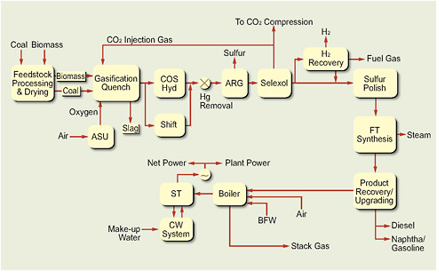
FIGURE 4.2Schematic of generic plant for indirect conversion of coal and/or biomass.
Source: Tomlinson and Gray, 2007.
synthesis gas. They are generally smaller and operate at lower pressures and tem-peratures than do coal gasifiers. Although there are many fixed-bed biomass gasifiers, fluid-bed and recirculating-bed systems have been developed.
A 3000 tons/day coal gasifier would produce enough synthesis gas to yield transportation fuel at about 6000 bbl/d by indirect liquefaction. After being ground into very small particles, the coal can be slurried with water or fed dry into the gasifier with a controlled amount of air or oxygen and steam. Temperatures in a gasifier range from 1400°F to 2800°F. At such high temperatures in the gasifier, steam reacts with the carbonaceous material of the feedstock to form syngas.
Coal Gasification
A number of technologies have been developed for coal gasification; they include moving-bed, fluid-bed, circulating-bed (transport), and entrained-flow gasifiers (MIT, 2007). The operating temperature and the size of coal feed vary with the type of gasifier. The moving-bed gasifier was developed by Lurgi and improved by Sasol. It operates at 425–600°C and accepts coal feed sizes of 6–50 mm. The
Sasol–Lurgi gasifier has been used extensively at the Sasol commercial plant in South Africa. Entrained-flow gasifiers operate at 1250–1600°C and accept coalfeed particles smaller than 100 μm. Those oxygen-blown, high-pressure gasifiers have been developed by General Electric (it was formerly referred to as the Texaco gasifier), Shell, Conoco Phillips (E-Gas), and Siemens (formerly referred to as the Future Energy gasifier). Fluid-bed gasifiers are less developed than the other two types. They operate at 900–1050°C and can use coal feed of 6–10 mm. In most types of gasifiers, avoiding soft ash particles is essential because the particles stick together, stick to process equipment, and typically lead to shutdown (MIT, 2007).
Coal gasification is commercially deployable today by using any one of several gasification systems that are being commercially used. Producing coal-to-liquid (CTL) fuels and other applications of gasification will lead to further improvements in the technology so that it would become more robust and efficient by 2020. Those improvements are part of the usual evolution of any new technology.
Coal and Biomass Gasification
Adding sustainably grown and harvested biomass to the coal feedstock would allow an increase in domestic fuel supply while reducing total greenhouse gas emissions in two ways. First, the emission of carbon in the burning of the fuels made from biomass is countered by the removal of carbon from the atmosphere by the biomass through photosynthesis during its growth. Second, the biomass and coal carbon that is converted to CO2 during the conversion to transportation fuels could be captured and stored.
The notion of gasifying mixtures of coal and biomass to produce liquid fuels is relatively new, and there has been little commercial experience. Many gasifiers can gasify biomass, but most of them are small in scale, use air instead of oxygen, and operate at lower temperatures and at low or atmospheric pressure. Under those less severe conditions, pyrolysis dominates, and the main products, in addition to syngas, are light hydrocarbons, bio-oils, tars, and char. Those products make such gasifiers less suitable for producing FT liquid fuels.
The NUON Shell 253-megawatt electric (253-MWe) integrated gasification combined-cycle (IGCC) facility in the Netherlands has proved that gasification of combined wood (30 percent by weight) and coal can be achieved for the generation of electric power. It has also gasified other biomass feedstocks, including chicken litter.
The operation of a combined coal-and-biomass-to-liquids (CBTL) plant would be similar to that of a CTL plant, except that biomass is gasified in addition to coal (Figure 4.2). Separate gasifiers could be used for the biomass and the coal, but it might be more efficient and cost-effective if the same gasifier could convert both feeds simultaneously. That would be similar to the situation at the NUON discussed above in which the Shell gasifier was able to gasify both wood and other biomass with the same lock-hopper high-pressure feeding system.
Combined coal and biomass gasification is deployable today, although the amount of biomass relative to coal feed is small, as discussed above. Further commercial development of the technology will make it more robust and efficient and enhance its ability to use higher fractions of biomass by 2020.
Biomass Gasification
Published data on high-pressure biomass gasifiers are sparse. Because of the fibrous nature of most biomass sources, the material is difficult to pretreat and feed into a high-pressure gasifier. Typical problems include clumping and bridging.
Biomass gasification exhibits many similarities to coal gasification, including the variety of gasifier types and different available approaches to gasification technology. However, the reaction conditions are generally milder than those for coal gasification because of the higher reactivity of biomass.
Gasification with direct firing with oxygen at higher pressures and temperatures produces a relatively pure syngas stream with small quantities of CO2 and other gases. For temperatures greater than 1000°C, little or no methane, higher hydrocarbons, or tar is present.
A major difference between biomass gasification and coal gasification is that the former generally involves smaller units than the latter because of the limits on the availability of biomass in a reasonable harvesting area. Biomass gasification therefore will not have the benefit of economies of scale that larger-scale coal gasification has. The lack of economies of scale will increase the cost per unit product of biomass gasification unless major process simplification and capital-cost reduction can be achieved. Like coal gasifiers, biomass gasifiers can be lumped into specific types, each of which has many variations.
Several U.S. and European organizations are developing advanced biomass gasification technologies, and about 10 biomass gasifiers have a capacity greater than 100 tons/day operating in the United States, Europe, and Japan (IEA, 2007; Cobb, 2007). Those units have a broad variety of feedstocks, feed capabilities,
characteristics, product-gas cleanup approaches, and primary products. The Biomass Technology Group lists more than 90 installations (most are small) and more than 60 suppliers of equipment that is used in gasification (Knoef, 2005). Although several of the available technologies have been commercially demonstrated, they have yet to be fully demonstrated commercially for integrated biomass gasification and transportation-fuel production. The panel considers biomass gasification to be technically ready for aggressive commercial demonstration but not yet well enough understood to ensure efficient, effective commercial deployment today. Many variations require understanding and improvement. With an aggressive commercial development program, biomass gasification technology could be ready for full-scale commercial deployment by 2015. The major issues to be resolved are related to engineering, particularly the extent of biomass pretreatment necessary and effective feeding of biomass to high-pressure gasification reactors. An example of the conversion of biomass into liquid transportation fuels is the partnership of Choren Industries and Shell. Choren provides the Carbo V gasification process, and Shell provides the FT synthesis technology.
Most of the gasification technologies present technical or operational challenges, most of which can probably be resolved or managed with commercial experience. Gasifier choice depends on the type of biomass feed and on the specific application of the gasification or pyrolysis products. The gasifier units will generally be smaller than large-scale coal gasifiers because of the economics and logistics of the feed supply. The most persistent problem appears to be related to biomass feeding, processing, and handling, particularly if a gasifier has to contend with different biomass feeds.
Syngas Cleanup and Conditioning
The raw syngas produced in the gasification of coal and biomass contains many impurities, such as CO2, hydrogen sulfide, carbonyl sulfide, ammonia, chlorine, mercury, and other toxic chemicals. Biomass has much lower sulfur content than coal does, and sulfur impurities in the syngas are correspondingly lower. However, biomass ash can contain high concentrations of sodium, potassium, and silicon that might pose additional requirements for the cleanup system. The impurities have to be removed before the syngas is allowed to contact the synthesis catalysts; otherwise, catalyst poisoning and deactivation will result. For example, in the conceptual configuration shown in Figure 4.2, carbonyl sulfide is hydrolyzed to hydrogen sulfide. Ammonia is scrubbed out and mercury is removed with acti-
vated carbon, and CO2 and hydrogen sulfide are removed with Selexol or another acid-gas removal system. The processes for removing the contaminants are all commercially available.
In addition to cleaning, the H2:CO ratio is adjusted to be compatible with the synthesis process by using the water–gas shift process. In this process, CO is converted by reaction with steam to H2 and CO2. The CO2 can then be removed in the acid–gas removal system to produce a concentrated stream of CO2 that is suitable for storage. The same is true for biochemical conversion of biomass to ethanol. The fermentation step produces a stream of pure CO2 that can be compressed and geologically stored. The transport and storage costs will be somewhat higher because the amount of CO2 will typically be smaller for the biochemical conversion route than for a thermochemical conversion route with an equal biomass feed rate. Because synthesis catalysts are readily poisoned by minute quantities of sulfur, a polishing reactor that removes sulfur down to parts per billion is included before the synthesis reactor. Ultimately, the hydrogen and carbonyl sulfides are converted (99.99 percent) to elemental sulfur, and the mercury is removed.
Syngas cleanup and conditioning technology is ready for full-scale commercial deployment today. It will undergo substantial improvement as a result of normal process evolution and become more robust and efficient by 2020.
Synthesis
Once the syngas produced by gasification of the carbonaceous feed has been cleaned of impurities and shifted to the desired H2:CO ratio, it can be used to synthesize liquid transportation fuels. Two major commercial synthesis processes can be used to produce transportation fuels, such as gasoline, diesel, and jet fuel. These are FT and methanol synthesis followed by MTG. DME can also be produced by dehydration of methanol, but it is not a liquid fuel under ambient conditions. DME is discussed in Chapter 9.
Fischer-Tropsch Synthesis
The clean synthesis gas is sent to FT reactors, where most of the clean gas is converted into zero-sulfur liquid hydrocarbon fuels. If the major required product is distillate or diesel boiling-range fractions, slurry-phase reactors are used. One of the limitations of FT synthesis is that it produces a wide array of hydrocarbon products in addition to some oxygenates. The array of products depends on the
probability of chain growth relative to chain termination. The probability function can theoretically be modeled with the Schultz–Flory–Anderson relationship, in which the parameter alpha determines the shape of the probability curve; the higher the alpha, the longer the hydrocarbon chains. To maximize liquid products in the naphtha and diesel boiling range, it is best to produce waxes first and then to crack the wax selectively to lower-boiling-point materials.
The low-temperature FT process produces about 10 percent hydrocarbon gases, 25 percent liquid naphtha, 22 percent distillate, and 46 percent wax and heavy oil. The wax can then be selectively hydrocracked into distillate. With this approach, the overall product distribution can be skewed in favor of diesel. The clean fuels are recovered, and the wax is hydrocracked into more diesel fuel and naphtha. The naphtha can be upgraded into gasoline, but substantial refining is necessary to produce high-octane material because of the paraffinic nature of naphtha. The CO2 in the FT tail gas is removed for storage, and the remaining synthesis gas is returned to the FT reactors for additional liquid production.
The FT process has been used for decades by Sasol and involves reacting synthesis gas over metal-based catalysts to yield a variety of hydrocarbons that can be converted to high-quality transportation fuels (gasoline, diesel, and jet fuel). The first such plant, known as Sasol I, used a combination of fixed-bed and circulating-fluid-bed FT reactors to produce the fuels. Recently, the Sasol I plant changed from coal to natural gas as feedstock, and it is now a gas-to-liquid (GTL) plant. In the early 1980s, Sasol built two large FT-based indirect coal-liquefaction facilities that together produce transportation fuels at over 160,000 bbl/d. The plants were designated Sasol II and III. Twenty years later, the plants are profitable, but they received government subsidies for several years after start-up. They would not have been economically viable in a market economy with relatively cheap oil and without government assistance.
FT synthesis is continuously being improved; since the building of the large Sasol plants, there have been substantial advances both in coal-gasification technologies that produce synthesis gas and in FT technology that produces clean fuels. The Sasol II and III plants originally used circulating-fluid-bed synthol reactors, which were later replaced by fixed-fluid-bed Sasol advanced synthol reactors. These are less expensive, are easier to operate, and have a much greater fuel-production capacity than synthol reactors. Research and development (R&D) at Sasol started experimenting with slurry-phase FT reactors in the early 1980s and built a 2,500-bbl/d prototype reactor at Sasol I to demonstrate and develop the technology. These reactors, which have operated on both iron and cobalt FT cata-
lysts, formed the basis for the huge slurry reactors that have been installed at the Oryx GTL plant in Qatar. The slurry reactors, with a diameter of about 36 ft, are each capable of producing fuels at 17,000 bbl/d.
Other companies are also developing FT reactor technology. Shell has developed the fixed-bed FT process known as the Shell middle-distillate synthesis process. Its GTL plant in Bintulu has been operating since the late 1980s, and recent improvements in the reactors and catalysts have increased the fuel-production rate substantially. ExxonMobil has developed a slurry-bed FT process with a patented cobalt-catalyst system that was the basis of its Qatar GTL plant design. The company withdrew that project from consideration in 2007 in favor of a liquefied-natural-gas plant. Conoco Phillips also has developed a FT system that was demonstrated on a pilot scale in Oklahoma. Syntroleum, another U.S. company, has also developed a somewhat different FT process for its GTL system. It has produced sufficient quantities of FT jet fuel for testing by the U.S. Air Force. The U.S. company Rentech has been developing an FT technology based on a slurry-bed reactor for a number of years and has recently built a pilot facility in Colorado. Other experimental FT systems are under development, including a microchannel reactor being tested by Velocys.
No commercial plant that combines advanced2 coal gasification with advanced FT technologies has been built. The only operating commercial-scale indirect CTL plants in the world are the Sasol plants. China—a country with increasing consumption of liquid fuels, a scarcity of domestic petroleum, and large coal resources—is moving rapidly toward commercialization of CTL technologies. The Shenhua direct-liquefaction process in Inner Mongolia launched its first trial operation of fuel production in December 2008.
FT synthesis technology can be considered commercially deployable today. Like several other ready-to-deploy technologies, it will undergo substantial process improvement by 2020, which will lead to more robust and efficient technology for producing liquid transportation fuels.
Methanol Synthesis and Conversion to Gasoline
The other major indirect liquefaction route involves the synthesis of methanol and its conversion to liquid transportation fuels. Methanol synthesis is a large-scale, commercial technology that can be supplied by several license holders and is used commercially to produce methanol from coal. It is well developed, is highly selective, and is used primarily to convert synthesis gas made from natural gas. The largest methanol plants can each produce about 5000 tons/day. Methanol is a feedstock for the manufacture of many chemicals and can be used as a fuel itself. Because of the ubiquity of methanol manufacture (Kung, 1980), that process is not discussed in detail here.
The MTG technology developed by Mobil Oil Corporation was demonstrated in a commercial plant in New Zealand (S. Tabak, ExxonMobil Research and Engineering Company, presentation to the panel on February 19, 2008). MTG technology produces mainly high-octane gasoline. A variant of MTG involves the conversion of methanol to olefins and their conversion to gasoline and diesel fuel and is referred to as MOGD. It has not been demonstrated commercially.
The key to the MTG process was the development of shape-selective zeolite catalysts that produce hydrocarbon molecules in the gasoline size range. The principal product is high-octane gasoline, and the secondary product is LPG. A plant with a capacity of 14,500 bbl/d was started in 1985 in New Zealand. It used natural gas as the feedstock and operated successfully for about 10 years. The drop in crude-oil and gasoline prices at the time resulted in curtailment of gasoline production and conversion of the plant to production of chemical-grade methanol. However, the improvements learned from the commercial operation in New Zealand are being incorporated into a second-generation plant under construction in Shanxi, China, by Jincheng Anthracite Coal Mining Company. The plant will feed coal-derived methanol and was scheduled to start in late 2008. The process uses gas-phase conventional fixed-bed reactors. A coal-to-fuels project in the United States is also planning to use MTG: a small-scale plant is under development by Consol Energy and Synthesis Energy Systems to convert West Virginia coal into gasoline at about 6000 bbl/d with the U-GAS® process followed by MTG. The development of that plant, however, was on hold in 2008 because of unfavorable economic conditions.
Figure 4.3 shows the schematic flow diagram of the New Zealand natural-gas-to-gasoline complex (Tomlinson et al., 1989), which converts methanol to 38.7 percent gasoline, 0.7 percent fuel gas, 4.6 percent LPG, and 56 percent water

FIGURE 4.3Schematic of New Zealand MTG complex.
Source: Adapted from Tomlinson et al., 1989.
by weight. The water is recycled as process water. Gasoline produced by the process is completely compatible with the conventional gasoline infrastructure, and it contains zero sulfur and is low in benzene (Tomlinson et al., 1989).
The panel considers standard MTG technology to be commercially deployable today, and, as indicated above, several projects are moving toward commercial deployment. Several variations of the technology are ready for commercial demonstration and could provide improvements in the standard MTG technology. They will evolve with commercial application and become more robust and efficient by 2020.
Challenges and Barriers to Deployment
Because the nation has more than 250 billion tons of recoverable coal reserves and because there is a considerable potential to provide large quantities of biomass, there is an opportunity to use the technologies described above to enhance U.S. energy security by producing clean, fungible transportation fuels to supplement the conventional petroleum supply. In spite of the large quantity of coal and continued high oil prices, there were no coal-liquefaction plants in the United
States in 2008, but several potential plants are in the development phase. This section discusses the environmental, economic, commercial, and social barriers to deployment.
The key components of CTL fuel technology have been commercially demonstrated and are ready for commercial deployment. However, from a technical and engineering standpoint, the integration of advanced entrained coal-gasification technologies, an advanced syngas cleanup process, and advanced slurry-phase FT synthesis technologies has never been demonstrated on the scale of a large synthetic liquid-fuel plant. The lack of experience poses a degree of technical risk that would be considered unacceptable by potential process developers and project funders. The panel believes that the technical barriers will be substantially reduced as soon as several first-mover plants become operational. The financial barriers will still be of concern because of the potential high variability of the energy markets. The technology is expected to evolve and improve with commercial experience and to become more robust and efficient.
Because of concerns about global climate change and greenhouse gas emissions, another major technical barrier is the demonstration that captured CO2 can be stored in geologic formations for extended periods in a safe, effective, and efficient manner. Resolving issues of potential long-term leakage and safety will require an aggressive program to demonstrate geologic storage and to develop data and procedures related to evaluation, permitting, injection, monitoring, and closure. That will also be needed to gain the political and popular support required to make geologic storage ready for multiple commercial deployments. The current status of the technology and the desired work remaining suggest that it will not be commercially deployable on a broad scale before 2015. Ideally, funds and programs for the design, construction, and operation of three commercial demonstrations of geologic storage in different geologic formations focused on gaining the CO2 storage information outlined above will be available soon. Such programs could be linked to indirect-liquefaction plants that use advanced technologies or coal-based power plants as total commercial demonstration of technologies with integrated carbon capture and storage (CCS). Two of the integrated facilities would be fed by coal of different rank and one by coal and biomass. One or two of the facilities could be operated to demonstrate geologic CO2 storage independently if integration of generation and storage causes a substantial delay in the demonstration of geologic storage.
Carbon Capture and Storage
The central issue in using coal in a carbon-constrained world is its inherently low ratio of hydrogen to carbon, which results in large CO2 emissions. Unless the resulting CO2 is captured during conversion and stored permanently (underground or by incorporating it in some other product), the life-cycle greenhouse gas emissions in converting coal to liquid fuels are about twice as great as those in producing and using fuels based on petroleum (Jaramillo et al., 2008; Bartis et al., 2008). Therefore, use of coal to produce liquid fuels in quantities needed to substitute for transportation fuels will require developing and demonstrating CCS on a large scale, which involves efficient and economic capture of CO2 and safe and efficient geologic storage. Demonstrating “the technical, economic, and environmental performance of the technologies that make up all of the major components of a large-scale integrated CCS project” (MIT, 2007, p. xi) will take billion-dollar investments by industry and government and could take a decade. Therefore, it is critical to start those demonstrations, with research involving multiple fully integrated monitoring and data-gathering activities, immediately (MIT, 2007). To date, few demonstrations of geologic storage of CO2 have been carried out on the needed scale. Governments and private companies have been hesitant to make the necessary investment that would ensure that the United States has a robust set of technologies that could be used for its energy future in the absence of any clear CO2-management policy. Without policy, there are no strong drivers, and the economics are negative.
Carbon dioxide capture is commercially deployable technology. Such processes as Selexol, Rectisol, and amine scrubbing are common in the petroleum and chemical industries. In indirect liquefaction, carbon dioxide is removed from the synthesis gas before production of liquid fuels, so the production of a concentrated stream of CO2 is an integral part of the processes. The concentrated CO2 stream can then be dehydrated and compressed for storage. Thus, it is possible to demonstrate any of several coal or coal–biomass processes commercially and to produce a concentrated CO2 stream for geologic storage with little impact on the cost of the liquid fuels produced.
Several projects are injecting megatonne quantities of CO2 each year into geologic formations, and no problems have been observed; but none of the projects is in the United States. Demonstrations in the United States that address the issues peculiar to the country and that are well planned and monitored are needed. In Norway, at the Sleipner Field in the North Sea, more than 1 million
tonnes of CO2 per year has been injected into a deep saline aquifer for more than a decade with no identifiable problems. The FutureGen program of the U.S. Department of Energy (DOE) intended to demonstrate CCS, but it was abandoned in 2007 when the estimated price doubled unexpectedly. However, DOE Regional Partnership projects to demonstrate larger-scale CO2 storage in various geologic formations are under way. Those projects need to be increased to true commercial size and moved forward much more rapidly if geologic storage is to be adequately demonstrated so that it can be used to store CO2 captured from coal plants in the needed timeframe. The government of the United Kingdom just announced a plan to carry out a demonstration on its soil, according to news accounts (Lovell, 2008), but has not taken steps beyond the announcement.
In the technical scenarios that are compared earlier in this chapter, the panel assumes that CO2 capture uses state-of-the-art technology, such as would be used in conventional refining and IGCC power plants. Such processes as Selexol, Rectisol, and amine scrubbing would be used. The processes considered produce a concentrated stream of CO2 as an integral part, so CO2 storage can be readily and more cheaply achievable. CO2 transport by pipeline is a well-demonstrated technology; such CO2 is used in enhanced oil-recovery (EOR) operations at about 35 million tons/year. Pipelining of CO2 poses no technical issues, but permitting issues are associated with obtaining rights-of-way, as is the case with most infrastructure projects. However, the technical and legal issues associated with the storage of captured CO2 still need to be clarified and resolved.
The estimates of potential costs of CCS in an earlier section are “bottom-up” and are based largely on engineering estimates of expense for transport, land purchase, permitting, drilling, all required capital equipment, storing, capping wells, and monitoring for an additional 50 years. However, experience suggests that the full cost of storage might not be captured by such an approach in light of barriers to implementation that increase cost. Uncertainties in the regulatory environment arising from concerns of the general public and policy makers are likely to evolve under the influence of future events (Palmgren et al., 2004). It is difficult to estimate such costs without some commercial-scale geologic storage experience, as outlined above. A reliable estimate of future cost of storage would contain, at least qualitatively, the uncertainty arising from such factors. Accordingly, quantified costs based on engineering analysis would probably represent a lower bound on future costs. (See Appendix K for a more detailed discussion.)
If liquid fuels produced by thermochemical conversion of coal or coal and biomass with CCS are to meet a sizable portion of U.S. demand for transporta-
tion fuels, more than a gigatonne of CO2 captured from such processes would have to be stored each year. CO2 capture and transport entail a potential health risk associated with acute leaks and with exposure of workers or populations to hazardous concentrations of CO2 near facilities. Geologic storage has the potential of an ecological risk to soils and groundwater as a result of chronic leakage and a warming risk associated with either sudden or chronic leaks that might partially or entirely vitiate the climatic value of a storage site (Anderson and Newell, 2004; Socolow, 2005). The public and policy makers are likely to anticipate those risks and require that they be taken into account in the design, monitoring, and carbon-accounting procedures and associated regulatory frameworks that would be part and parcel to storage (Wilson et al., 2007). As a result, timing estimates need to recognize the potential for delay in initiating demonstration projects because of lags in conception and development of the overall regulatory regime for storage and in licensing of each specific project, both in the demonstration phase and beyond. Some issues, such as liability insurance for near-term operation and long-term site maintenance, require political resolution that could introduce additional delays (IRGC, 2008). Uncertainty over the likelihood of long-term leaks could translate into regulations that require the sources that plan to store carbon to purchase allowances equivalent to fractions of the carbon stored. Such a requirement would increase the net cost of CCS. All those issues need to be evaluated as part of the several geologic-storage demonstration projects mentioned above to provide the best information for the evaluation of future commercial activities.
Once CCS attains full commercial-scale operation, delays could arise because of accidents that cause or threaten releases. Because the technologies, monitoring, and regulation of storage are likely to be closely related, if not identical among sites, interruption of operations at one site could affect operations at other sites; broadly reduce or temporarily eliminate storage; undermine the credibility of the technology among investors, regulators, policy makers, and the general population; and add a substantial risk premium to investment in CCS. Continuous storage operations might be subject to multiple regulatory regimes (and varied siting, licensing, and monitoring requirements) at various government levels. Those issues and potential causes of delay apply to other major commercial operations, including production, pipelining, and refining of crude oil.
CO2 is being used for EOR at the Weyburn oil field in Canada; CO2 from the Great Plains lignite gasification plant is used at almost 1 million tons/year. Statoil has been successfully injecting CO2 from the Sleipner gas field into the Utsira Formation, a deep saline aquifer, at more than 1 million tonnes/year for over a decade.
CO2 is also being reinjected at the Salah liquefied-natural-gas (LNG) project in Algeria at about 1 million tonnes/year. There has been no indication of problems arising from any of those projects, and the CO2 storage shows no sign of leakage.
EOR can present an opportunity for early CCS and can reduce the cost of CCS by providing a net return. Use of CO2 in EOR has been safe and has not raised any questions about the ability to store CO2 in proper geological formations safely over the long term. EOR in the United States uses CO2 at 35–40 million tonnes/year. There are opportunities for additional EOR, but those storages are small compared with the large amounts of CO2 that would be captured if CTL becomes widely deployed, potentially in the gigatonnes-per-year range. CO2 could be stored in deep coal seams, where it can displace methane for use in the natural-gas pipeline. CO2 binds more strongly to coal than does methane and thus replaces it; and just as the methane is permanently locked in the coal seam for extremely long times, the CO2 will be permanently stored there. Again, however, the use of CO2 in coal-bed displacement is small in relation to the total amounts that need to be stored.
With adequate demonstration and long-term monitoring, CCS could offer a way to use the nation’s wealth of fossil fuel while limiting adverse effects on climate. What is now needed is aggressive demonstration on a commercial scale in several U.S. geologic formations to develop the needed data and to understand and resolve issues.
Supply of Feedstock
Deployment of such facilities will require the use of large quantities of coal and thus an expansion of the coal-mining industry. For example, a 50,000-bbl/d plant will use about 7 million tons of coal per year, and 100 such plants producing liquid transportation fuels at 5 million bbl/yr would require about 700 million tons of coal per year—a 70 percent increase in coal consumption. That would require major increases in coal mining and transportation infrastructure to move coal to the plants and fuel from the plants to the market. Those issues could pose major challenges, but they could be overcome.
The next question is whether sufficient coal is available in the United States to support such increased use. The National Research Council evaluated domestic coal resources (NRC, 2007) and concluded:
Federal policy makers require accurate and complete estimates of national coal reserves to formulate coherent national energy policies. Despite significant uncertainties in existing
reserve estimates, it is clear that there is sufficient coal at current rates of production to meet anticipated needs through 2030. Further into the future, there is probably sufficient coal to meet the nation’s needs for more than 100 years at current rates of consumption. … A combination of increased rates of production with more detailed reserve analyses that take into account location, quality, recoverability, and transportation issues may substantially reduce the number of years of supply. Future policy will continue to be developed in the absence of accurate estimates until more detailed reserve analyses—which take into account the full suite of geographical, geological, economic, legal, and environmental characteristics—are completed.
The Energy Information Administration (EIA) recently estimated the proven U.S. coal reserves to be about 260 billion tons (EIA, 2009). A key conclusion of the NRC and EIA studies is that there are sufficient coal reserves in the United States to meet the nation’s needs for more than 100 years at current rates of consumption. Even with increased rates of consumption, ramped up over time, the reserves could support our needs for 100 years. The primary issue probably is not the reserves but the increase in mining of coal and the opening of many new mines. Increased mining has numerous environmental effects that will need to be dealt with in an environmentally acceptable way. Public opposition to increased coal mining is to be expected because of the need to open new mines and the environmental implications of mining more coal. Increasing coal use will undoubtedly increase the cost of coal, but coal costs are relatively low, and substantial amounts of coal can probably be produced at current or slightly higher prices.
A particular barrier to the establishment of biomass-to-liquids (BTL) plants is the availability of sufficient quantities of feedstock in a reasonable area. Because only small quantities of biomass (3000 tons/day) can be gathered, such plants will be limited in size by feedstock constraints. That leads to small-scale plants and hence diseconomies of scale and high capital cost. Another challenge is the successful feeding of raw biomass to high-pressure gasification systems. Biomass, unlike coal, is soft and fibrous and difficult to reduce to the small sizes necessary for gasification. A third challenge is to reduce the high costs of biomass feed, including the costs of growing, harvesting, and transportation to the conversion plant. Biomass has very low energy density when raw, so transportation costs are high compared with the cost of coal, which is high in energy density.
Efforts to increase the energy density of raw biomass by pyrolysis are under way. Lurgi and Air Liquide have an interesting concept for conversion of low-energy-density biomass to liquid fuels. Biomass, such as switchgrass or woody biomass, is pyrolized in a double-screw retort with hot sand as the heat-transfer medium. The biomass degrades to form pyrolysis oil and char. The pyrolysis
oil and char are mixed together to form a “bio-syncrude,” which has an energy density 13 times that of the unprocessed biomass and contains 80 percent of the energy in the biomass. The bio-syncrude can be readily transported and fed to the Lurgi multipurpose gasification (MPG) process or other gasification processes to produce syngas, which can then be cleaned and used to synthesize liquid transportation fuels by FT. The concept appears to overcome the problems of transporting low-energy-density raw biomass and feeding raw or pretreated biomass to high-pressure gasification. The initial pyrolysis could conceivably be done on a field scale, and the high-energy-density bio-syncrude could be shipped to a central gasification facility for production of transportation fuels.
Economics and Investment
The uncertainty of future oil prices is an important barrier to deployment of CTL, as is the high capital expenditure needed for commercial CTL plants. A 50,000-bbl/d plant could cost $4–5 billion, so the plants could be expected to approach $100,000 per daily barrel, which is about 6 times as high as deepwater Gulf of Mexico crude-oil capital investment costs. The investment risk for such a large expenditure is considerable. In that context, it should be noted again that biorefineries for converting cellulosic biomass to ethanol have an estimated capital cost of about $120,000 per daily barrel of gasoline equivalent and that about 30 biorefineries (with production capacity of 40 million gallons of ethanol per year) are required for a 50,000-bbl/d output.
Infrastructure and Labor
If many plants are built worldwide at the same time, there will be competition for critical process equipment and engineering and labor skills. On the basis of parallels with the indirect-liquefaction industry, the timeline for commercial deployment in the United States would be long. Permitting and the usual public reluctance to accept the need for new facilities, especially coal-based plants, are issues. The proposed FT plant for conversion of anthracite residue to clean diesel fuel, to be built in Gilberton, Pennsylvania, has been in gestation for 12 years, and construction apparently has yet to begin. The Dakota gasification plant (which produces substitute natural gas from lignite) in Beulah, North Dakota, was originally proposed in the late 1960s and came on line in the early 1980s—a time span of some 12–15 years. Even if permitting and other legal issues do not impose a delay, it would still take at least 6 years to construct an indirect-liquefaction plant.
For example, the Sasol II and III complexes in South Africa required 6 years to construct from the time the South African government approved the plans.
Technology Forecast
Technologies Deployable in 2008–2020
The discussion above is related to technologies that are deployable now or potentially deployable in the near future. CTL plants that use gasification followed by FT or MTG synthesis can be built today. Although integration of advanced entrained coal gasification with FT has not been commercially demonstrated, the technical risk associated with such a venture is low because of the separate experience with commercial gasification for other applications and commercial use of FT in CTL and GTL processes. Because of the challenges listed above and the long lead time required for planning, detailed design, permitting, and construction, it is unlikely that any CTL plants will be in commercial operation in the United States before the 2015–2020 timeframe. CTL plants with CCS will probably take longer to be commercialized because of the need for commercial demonstration of carbon dioxide storage and monitoring before it can be applied broadly in commercial operation.
With some additional R&D focused on biomass pretreatment and feeding to gasification reactors, CBTL plants that coprocess small amounts of biomass (up to 30 weight percent) could be deployed today. Their rate of deployment would be subject to the same restrictions as the rate of deployment of CTL plants, and there is the additional issue of biomass availability and suitable plant site location. With the benefit of successful biomass pretreatment, small-scale thermochemical BTL plants using current biomass gasification and FT or MTG technology could also be deployed today.
With respect to deployment of future technologies, the panel’s review of the thermochemical-conversion technologies has separated them into two groups: those likely to be deployable in 2020–2035 and those requiring longer-term R&D.
Technologies Likely to Be Deployable in 2020–2035
Continued advances in both coal and biomass gasification technologies after 2020 are likely. For example, Pratt and Whitney Rocketdyne is developing a compact gasifier based on rocket-engine technology that, if proved successful, could reduce costs and improve efficiencies. The production of synthesis gas is the most capital-
intensive section of a thermochemical conversion plant, so cost reductions in that component would greatly improve overall economics.
As long as industrial interest in alternative fuels continues, the synthesis process—whether FT, MTG, or MOGD—is likely to undergo continuing improvement. For example, Velocys is developing a microchannel FT process that could improve synthesis gas conversion and reduce costs. With continued emphasis on climate change, successful demonstration and practice of CCS is likely to be attained, greatly accelerating the ability to deploy thermochemical fuel plants with safe CCS.
Another option for the conversion of syngas to liquids, other than FT, is catalysis (Chu et al., 1995; Herman, 2000). Syngas can be converted catalytically through the chain-growing process to such higher alcohols as isobutanol in a slurry-phase reactor. Better catalysts and reactor design are needed to improve the yield and selectivity of the catalytic conversion of syngas to higher alcohols (Herman, 2000; Li et al., 2005). The development and deployment of improved syngas cleanup, including reduction of hydrogen sulfide to parts-per-billion concentrations, are required to minimize catalyst poisoning. Then, the technology needs to be demonstrated on a semi-work scale for commercial deployment.
A novel approach that has potential for commercialization is chemical-looping gasification. In that process, a metal oxide is used as an oxygen carrier and is itself reduced to metal. The metal can then be reacted with steam to produce hydrogen and/or carbon monoxide, which can then be used to produce liquid fuels, chemicals, and electricity (Fan and Iyer, 2006; Fan and Li, 2007; Gupta et al., 2007). An example is the syngas chemical-looping process that has the potential to convert coal to hydrogen at 7–10 percent higher efficiency than conventional coal-to-hydrogen processes (Gupta et al., 2007). Furthermore, the syngas chemical-looping scheme can be integrated into the conventional CTL process (Gupta et al., 2007; Tomlinson and Gray, 2007), allowing the by-products of liquid-fuel synthesis to be converted to hydrogen. Such integration can lead to a 10 percent increase in liquid-fuel yield and a 19 percent decrease in carbon emission (Tomlinson and Gray, 2007). The full operability of the new process needs to be tested on a pilot scale. The feasibility of the technology will then have to be shown in a demonstration plant for later commercial deployment.
Combining technologies in a plant could result in improvements in the product slate, reductions in greenhouse gas emissions, or other benefits compared with a plant that uses a single technology. For example, it is well known that indirect liquefaction with FT produces an excellent high-cetane diesel fuel, but FT naphtha
is not well suited for gasoline. In contrast, the MTG process produces a high-octane gasoline with very high selectivity. Therefore, one might envision a plant in which syngas is split between FT and MTG to obtain the best of both: high-quality gasoline and diesel. Another example is potential reduction in greenhouse gas emissions through use of nuclear process heat as the source of process heat for thermochemical conversion of coal, biomass, or combined coal and biomass. Coupling a nuclear power plant with a synthetic-liquid-fuel facility could have, as one benefit, the elimination of greenhouse gas emissions from furnaces and other heaters throughout the synthetic-fuel production side of the plant.
Technologies Likely to Be Deployable After 2035
Technologies presented in this section are ones for which substantial R&D effort is still needed, but they could potentially provide drastic improvement to thermochemical conversion. Those technologies will probably not be realized until after 2035. Despite many apparent differences among process strategies, virtually all processes for thermochemical conversion of biomass and coal have several characteristics in common. They rely on the thermal breakdown of the feedstock (typically at 350°C or above) to produce a population of free-radical intermediates that undergo a complex sequence of reactions, they tend to produce a mixture of products rather than showing high selectivity to a single desired product, and they yield 2 ± 0.5 bbl of liquid product per ton of feedstock.
Technological developments that are beyond incremental improvements will probably have to be based on different ways of breaking apart the macro-molecules in the feedstock rather than relying on thermally driven bond-breaking. There are several potential developments. One is changing the reaction intermediates from radicals to positively charged carbon atoms (carbocations); this could be done with Lewis acid catalysts, for example. Consolidation Coal Company has investigated the direct liquefaction of coal in molten zinc chloride and reported high selectivities to gasoline. A second is enzymatic bond cleavage with fungi, bacteria, or other organisms engineered to have enzymes with high activity and selectivity for cleavage of particular kinds of bonds. A third is the application of energy to cleave bonds in much more targeted fashion with, for example, microwave heating or ultrafast (femtosecond) lasers tuned to specific bonds.
A major step forward will need to be based on a thorough understanding of the molecular structures of the feedstocks and of the specific kinds of bonds to be broken. The molecular features of coal, in particular, are not well understood and are thought to vary from one kind of coal to another.
Pennsylvania State University has developed two approaches for introducing coal or coal extracts into oil refineries (Clifford and Schobert, 2007). One involves extraction of coal with a petroleum solvent, such as light-cycle oil, followed by two-stage hydrotreating of the extract mixture. Fractionation after hydrotreating provides mainly clean jet fuel and diesel as products and smaller amounts of gasoline and heating oil. The second approach blends coal with the feed to delayed cokers. The coker liquid is mainly in the fuel-oil range with smaller amounts of lighter distillates. The university has licensed the technology to CoalStar Industries, Johnstown, Pennsylvania. CoalStar Industries is planning to build a 10,000-bbl/d demonstration and is in the final stage of selecting a site for the plant, which will probably be in southwestern Pennsylvania (D. Fyock, CoalStar Industries, personal communication, November 6, 2008).
Research, Development, and Demonstration
If the goal is to increase production of domestic liquid transportation fuels in the next several decades to enhance energy security, it is important to rapidly advance technologies that are commercially deployable today if their economics justify the deployment. Those first movers would need to have an associated applied R&D program to ensure success and to develop learning. An R&D program that addresses step-out technology improvements and developments and that develops new technologies also needs to be supported. Engaging in a new research program on the assumption that it will provide energy solutions in the near to middle term is unwise.
For thermochemical technologies that are deployable now, the financing hurdle remains serious primarily because of the volatility of the energy markets; but deployment is also affected by uncertainties in climate-change policy and by lack of full-scale commercial demonstration. The energy market’s uncertainty is illustrated by the price of crude oil over the last 3 years and its decrease from a high of $147/bbl to a low of $32/bbl in 5 months. The projects in question have a multiyear timeline from planning to operation, and they require capital of $1–5 billion or more. They face what has often been referred to as a valley of death in getting from development and demonstration to commercial deployment. Reaching commercial deployment will probably require a number of commercial first-mover projects combined with geologic storage of CO2 to gain commercial experience and to move the technology to robustness and to substantial cost reductions for the Nth plant, where N is a small number. The commercial first-mover proj-
ects would include a major R&D component to focus on solving problems and to develop technology for specific improvements. That would improve the technologies, quantify their relative costs, and reduce the risk associated with their commercial deployment if they show economic competitiveness. The panel considers this phase critically important for facilitating commercial deployment of thermochemical technologies.
An R&D program should be associated with commercial-scale demonstrations of geologic CO2 storage. The demonstrations need to involve detailed geologic research and a broad array of monitoring tools and techniques before initiation, as they proceed, and after they are closed to provide the understanding and data on which future commercial projects will depend. Because of the scale of geologic storage, research and monitoring need to be continued at a steady rate, after the demonstration projects are declared completed. Increased research efforts on the coal-mining end of the value chain are also warranted to improve understanding of the immediate and longer-term environmental effects of increased coal mining and use.
On the gasification and gas-treatment side, the current research program focuses on broadly applicable improvements. Continuation of that program would provide improved coal pumps, ion-transport membranes for oxygen separation, membranes for other separations, and various other technology improvements.
New catalysts and catalytic routes to liquid transportation fuels need continued study because those step-out technologies offer much potential. Likewise, new reactor concepts or separation concepts offer much potential. As new ideas come along, they need to be evaluated and their economic potential analyzed. The section “Technologies Likely to Be Deployable After 2035” above contains a number of new process concepts that require focused R&D. The ones that meet needs can be advanced to the process-demonstration stage to obtain data for evaluating commercial potential.
Costs and Performance
Between now and 2020, technologies for the thermochemical conversion of coal, biomass, and coal–biomass mixtures by gasification followed by FT synthesis or methanol synthesis followed by an MTG process will probably be commercially deployed in the United States and in other countries that have large coal resources, such as China, Russia, India, and Australia. To reduce the CO2 footprint of CTL plants, CCS technologies will have to be used. Capture of CO2 from CTL plants
uses the same state-of-the-art technology used in conventional refining, natural-gas processing, and IGCC facilities—for example, Selexol, Rectisol, and amine scrubbing. CTL plant configurations produce a concentrated stream of CO2 as an integral part of the process, so CO2 capture can be readily and more cheaply achievable than, for example, in IGCC or pulverized-coal plants. The higher cost of CO2 avoided3 with IGCC is a result of the fact that an IGCC plant without CCS would use a different configuration from one with CCS. An IGCC plant without CCS does not have water–gas shift and does not separate CO2 in the gasification–purification train. In contrast, water–gas shift and CO2-separation equipment has to be included in an IGCC plant that practices CCS, and this increases the cost of the plant. The higher cost and added energy use of an IGCC plant with CCS results in a much higher cost of CO2 avoided. In contrast, the only difference between CTL plants that vent CO2 and CTL plants that use CCS is the need to dehydrate and compress the concentrated CO2 stream that would otherwise be vented.
Because there are no thermochemical-conversion plants in the United States, this section provides a detailed technical and economic analysis of conceptual plants simulated with Aspen Plus software. Both indirect- and direct-liquefaction models have been developed.
To evaluate the commercial potential of coal conversion to liquid transportation fuels, the panel carried out a series of evaluations of various conversion processes and options. They all used a consistent capital-cost basis and the same set of economic and operational parameters.4 Thus, the relative costs of fuels produced with different processes and among different options for a given process are quite accurate, although substantial uncertainty may be associated with the absolute cost. Details of this approach and the capital-cost basis and the economic and operational parameters used are given elsewhere (Kreutz et al., 2008).
Indirect-liquefaction models include CTL, BTL, CBTL, and combined electric-power and fuel generation (polygeneration). To keep the extent of work
and the number of cases evaluated within reason, a number of parameters were fixed, such as gasifier type, coal type, and location. For example, the analyses were all based on a Texaco–GE entrained-flow gasifier and Illinois no. 6 coal.5 Equipment capital costs were from recent detailed design studies and were updated to 2007 dollars on the basis of the Chemical Engineering Plant Construction Cost Index. Plant design involved material-balance and energy-balance calculations with Aspen Plus. Most of the studies were based on a synthesis-process configuration that involved recycling of unconverted synthesis gas leaving the reactor back to the reactor to achieve maximum synthesis of hydrocarbons. The configuration will be referred to as recycling. The recycling cases included designs both with and without CCS. The designs involved generation of power from fuel-gas streams for use in the plant, and excess power was sold to the grid. Some of the designs involved passage of synthesis gas through the synthesis reactor without recycling of the unconverted fraction and with generation of power from the unconverted gases and are referred to as once-through cases. Those cases typically produced large quantities of power. They also included designs with and without CCS. The costs and performance estimates cited here correspond to those in a workbook that is available at http://cmi.princeton.edu/NRC_AEF_workbook.
Coal to Liquid Fuels
Table 4.1 summarizes the results of the analysis of conceptual CTL plants operating in the recycle mode with and without CCS (Kreutz et al., 2008; Larson et al., 2008). Each column shows the performance, cost, and greenhouse gas life-cycle emissions for the indicated process configuration. Figure 4.4 shows the plant configuration with the main process units indicated for diesel and gasoline production using FT synthesis. The plant has FT reactor tail-gas recycling and venting of the CO2 recovered from the synthesis gas to the atmosphere. In this configuration, an autothermal reformer is used to convert the light hydrocarbon gases produced during synthesis back into synthesis gas, which is then sent to the FT unit for further conversion into liquid fuels. The paraffinic diesel and the higher-range material made require additional refining to produce high-quality diesel and jet fuel. The naphtha-range material has a low octane number and thus requires substan-
TABLE 4.1 Coal to Liquid Fuels by Fischer-Tropsch and Methanol to Gasoline Conversion Routes With and Without Carbon Capture and Storage
| CTL FT Recycling Without CCS | CTL FT Recycling With CCS | CTL MTG Recycling Without CCS | CTL MTG Recycling With CCS |
Inputs: |
|
|
|
|
Coal, tons/day (as received) | 26,700 | 26,700 | 22,900 | 23,200 |
Outputs: |
|
|
|
|
Diesel, bbl/d | 28,700 | 28,700 | 0 | 0 |
Gasoline, bbl/d | 21,290 | 21,290 | 50,000 | 50,000 |
Total liquid fuels, bbl/d | 50,000 | 50,000 | 50,000 | 50,000 |
Efficiency, percent (low heating value) | 49.1 | 47.6 | 54.2 | 52.9 |
Electricity, MWe | 427 | 317 | 145 | 111 |
CO2 vented at the plant, tonnes/hr | 1,427 | 209 | 1,200 | 230 |
CO2 stored, tonnes/hr | 0 | 1,217 | 0 | 970 |
Economics and metrics: |
|
|
|
|
Total plant cost (TPC), millions of dollars | 4,880 | 4,950 | 3,940 | 4,020 |
Specific TPC, $/bbl per day | 97,600 | 98,900 | 78,800 | 80,400 |
Total liquid fuels cost,a $/gal gasoline equivalent | 1.50 | 1.64 | 1.47 | 1.57 |
Break-even oil price,b $/bbl | 56 | 68 | 47 | 51 |
Life-cycle GHG emissions, kg CO2eq/GJ (low heating value) | 205 | 98 | 192 | 109 |
FT liquids per petroleum-derived diesel emissions | 2.23 | 1.07 | 2.09 | 1.18 |
Cost of avoided CO2, $/tonne | Not applicable | 11 | Not applicable | 10 |
Fuel cost: |
|
|
|
|
With $10/tonne CO2, $/gal gasoline equivalent | 1.71 | 1.74 | 1.69 | 1.69 |
With $50/tonne CO2, $/gal gasoline equivalent | 2.58 | 2.12 | 2.52 | 2.18 |
With $100/tonne CO2, $/gal gasoline equivalent | 3.67 | 2.60 | 3.66 | 2.79 |
Note: Details of models can be found in Kreutz et al. (2008) and Larson et al. (2008). aFor simplicity and consistency, the panel assumed that electricity was sold to the grid at the average 2007 generating price in the United States, which was $60/MW with $0/tonne of CO2 charged. All table entries have that basis. If the value of the electricity is set at $80/MW, the total liquid-fuels cost decreases from $1.50/gal gasoline equivalent to $1.41/gal gasoline equivalent for CTL FT venting and from $1.64/gal gasoline equivalent to $1.58/gal gasoline equivalent for the CO2 storage version. For $50/tonne of CO2, the fuel cost decreases by $0.90 for venting and by $0.36 for CO2 storage. bThe break-even crude-oil price is defined as the price of crude oil in dollars per barrel at which the wholesale prices of petroleum-derived products would equal (on a dollars-per-gigajoule basis) the calculated cost of production of the synthetic fuels. See Kreutz et al. (2008) for a detailed definition. | ||||
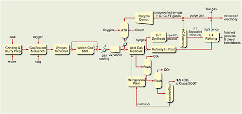
FIGURE 4.4Schematic of plant for production of diesel and gasoline from coal with FTsynthesis, recycling of unconverted syngas, and reforming of light hydrocarbons; separated CO2is vented to the atmosphere.
tial refining to produce high-octane gasoline. The estimates in Table 4.1 include the cost of upgrading to fuel products. Details of the Aspen Plus modeling and other aspects of the analysis are presented by Kreutz et al. (2008).
That commercial-scale conceptual plant produces gasoline and diesel at 50,000 bbl/d from 26,700 tons of as-received bituminous coal per day. That yields a ratio of 1.9 barrels (80 gal) per ton of coal and an overall plant efficiency of 49 percent (on the basis of the lower heating value [LHV]). The plant generates 874 MW of electric power; 447 MW are needed on site, and 427 MW are sold to the grid. In this configuration (Figure 4.4), the CO2 produced during the conversion process, amounting to 1427 tonnes per hour, is vented to the atmosphere. The CTL plant with CCS takes advantage of the higher pressure of the CO2 coming off the acid-gas removal flashes to minimize the compression-power requirements but still consumes more than 100 MW in compression-power consumption, reducing the plant export of power to the grid to 317 MW of electricity.
Figure 4.5 shows the schematic of a coal-to-gasoline plant that uses methanol synthesis followed by MTG. The plant uses the same equipment at the same size from coal storage up to the front of the synthesis loop as the FT plant. Because

FIGURE 4.5Schematic of plant for production of gasoline from coal with methanol synthesis followed by MTG process with recycling and CCS.
of the higher selectivity of the methanol synthesis and MTG conversion, the remainder of the plant is less complex than the FT plant. The plant vents the CO2 separated from synthesis gas to the atmosphere and uses recycling of unconverted gases around the methanol-synthesis reactor. To be consistent with the FT plants producing only liquid transportation fuels and power, the LPG produced in the MTG process was burned to produce electricity in the power island. The plant produces gasoline at 50,000 bbl/d from 22,900 tons of as-received subbituminous coal per day. The MTG scheme yields 2.2 bbl of gasoline per ton of coal and an LHV plant efficiency of 54 percent. The somewhat higher liquid yields occur because the methanol syntheses and MTG are more selective in their conversion efficiency and gasoline is less dense than diesel fuel. The plant generates an estimated 440 MWe and sells an estimated 145 MWe to the grid. Good engineering data on the MTG portion of the plant are lacking, and the estimates of generated power need to be refined as better data become available. Higher plant efficiency occurs because the MTG plant produces less electricity, which has a lower efficiency of production. The plant vents CO2 at about 1,200 tonnes/hr.
To estimate the total life-cycle greenhouse gas emissions from these processes (from coal mine to wheels), it is necessary to estimate the total emissions resulting from the mining and the transportation of the coal from the mine to the plant,
including methane emissions from mining, emissions associated with fuel distribution from the conversion plant to the end user, emissions due to conversion processes at the plant, and emissions resulting from the combustion of the fuels produced.6 Because the plants produce excess power, a greenhouse gas credit is given for power production on the basis of the greenhouse gas emissions associated with an IGCC plant that generates the same amount of power and has no CCS.
This carbon-accounting method estimates the life-cycle emission for the venting CTL FT case to be 205 kg CO2 eq/GJ (LHV) of produced fuels (about 1 ton of CO2 per barrel of product) and about 192 kg of CO2 eq/GJ (LHV) of produced fuels for the coal-to-methanol-to-MTG case. For production of the fuels from conventional petroleum, the greenhouse gas life-cycle emission is estimated from Argonne National Laboratory’s Greenhouse Gases, Regulated Emissions, and Energy Use in Transportation (GREET) model to be about 92 kg CO2 eq/GJ. Therefore, the life-cycle emission is about 2.2 times that of fuels produced from petroleum.
The capital cost (total plant cost) of the FT plant without CCS (first column in Table 4.1) is estimated to be $4.9 billion. That is equivalent to a capital cost on a daily-barrel basis of $97,600. For the consistent economic parameters used in this report, a coal price of $42/ton ($1.71/GJ), and an electric-power value of $60/MWh, the resulting cost of the fuels would be $1.50/gal gasoline equivalent. In terms of a break-even oil price, that translates to $56/bbl (see Table 4.1 footnote for definition). If electricity is valued at $80/MW rather than $60/MW, the fuel-production cost decreases by $0.09/gal gasoline equivalent to $1.41/gal gasoline equivalent, and the decrease remains $0.09/gal gasoline equivalent for the several CO2 cost entries in the table. The total plant cost of the MTG plant is estimated at $3.9 billion (third column of Table 4.1); on a daily-barrel basis, the capital cost is $78,800 per stream-day barrel (SDB). That is lower than the cost of the FT plant because of the somewhat higher complexity of the FT process and the larger refining requirement to produce fuels that meet the product specifications. The resulting cost of the high-octane gasoline produced is estimated at $1.47/gal, which equates to a break-even oil price of about $47/bbl. The impact of $80/MW
versus $60/MW is a $0.04/gal gasoline equivalent reduction in fuel cost because an MTG plant sells less electricity than an FT plant does. For MTG, if LPG is sold at the current market price, the cost of fuel production decreases by about $0.20/gal gasoline equivalent to $1.26/gal gasoline equivalent. Those costs for the production of liquid transportation fuels from coal are comparable to the costs in a report by the RAND Corporation (Bartis et al., 2008).
The economic results shown above are for cases in which there is no tax on CO2. If CO2 were to be taxed in the future so that a plant operator had to pay to emit CO2 to the atmosphere, the economic situation could change substantially. If the tax imposed on CO2 were $100/tonne, the cost of fuel from this coal-based FT plant would increase from $1.50/gal gasoline equivalent to $3.67/gal gasoline equivalent. The MTG plant would see a similar impact on the cost of the gasoline produced and an increase from $1.47/gal gasoline equivalent to $3.66/gal gasoline equivalent.
The second and fourth columns in Table 4.1 summarize the results for the conceptual FT and methanol-to-MTG plants with recycling and with CCS. In this case for FT, bituminous coal at 26,700 tons/day produces liquid fuels at 50,000 bbl/d. Overall plant efficiency is reduced slightly, from 49 to 48 percent, in this case because of the need to compress and dry the captured CO2 to 2,100 psi for pipelining and geologic storage. About 85 percent of the CO2 produced during the conversion process is captured, and only 209 tonnes/hr are emitted to the atmosphere. Although the fuel output is the same with and without CCS, the net electric-power generation is reduced to power the compressors for the captured CO2. A greater percentage of the CO2 produced in the conversion process could be captured by changing the overall configuration to include, in addition to an autothermal reformer, additional water–gas shift and CO2 capture facilities to produce more H2, which could be used as fuel in the gas turbine in the combined-cycle power island. The same comments apply to the methanol-to-MTG case.
With the same method as in the previous case (except that the electric-power greenhouse gas credit is now based on an IGCC plant with CCS), the greenhouse gas life-cycle emission is estimated to be reduced to 98 kg of CO2 eq/GJ for the FT unit producing liquid fuels. The ratio of the greenhouse gas life-cycle emissions for the FT liquids to that for petroleum-derived diesel is 1.1, which means FT liquids essentially have the same greenhouse gas life-cycle emissions as petroleum-derived fuels. The ratio must be interpreted carefully. The assignment of the greenhouse gas emissions associated with the generation of the excess electric power is somewhat arbitrary and depends on the power-generation technology that is displaced
at the margin. It could be CO2-free if power from nuclear energy were displaced, or the greenhouse gas emission credits could be high if power from conventional pulverized-coal plants were displaced. The method used in these analyses assumes that the reference plants are IGCC with no CCS for comparisons with venting cases and IGCC with CCS for cases with CCS. Thus, a consistent basis is used for assessing the greenhouse gas credit given to the excess power generated by these CTL plants. In addition, the assignment of the greenhouse gas life-cycle emissions for the production of low-sulfur diesel from conventional petroleum is arbitrary. There can be no single value for it. Crude oil varies in composition and in its ability to be refined, and refineries have different efficiencies and use a wide variety of refining processes. So, at best, the life-cycle emission can be only an approximate average. As a result of those uncertainties, a ratio of greenhouse gas emissions for coal-derived liquid fuels to emissions for petroleum-derived fuels of around 1 implies that the greenhouse gas emissions for the overall cycle can be about the same as or less than that for petroleum. In addition, if more CO2 were captured in the coal-to-fuels conversion process by changing the process configuration, the life-cycle emission for the coal-to-fuels process could be further reduced to less than that of petroleum-derived fuels.
The capital cost of the FT plant with CCS is estimated to be about $5 billion, which is equivalent to a capital cost on a daily-barrel basis of just under $100,000. For the consistent economic parameters used in this analysis, the resulting cost of the fuels would be increased from $1.50/gal gasoline equivalent in the venting case to $1.64/gal gasoline equivalent in the CCS case. The cost of CO2 avoided by this configuration is about $11/tonne. Those economic results are for a case in which there is no tax on CO2 or equivalent shadow price reflecting cap-and-trade emission cost. If a carbon price of $100/tonne of CO2 were imposed on fuels, the cost of fuel from this plant would increase from $1.64/gal gasoline equivalent to $2.60/gal gasoline equivalent, and the equivalent crude cost would be about $109/bbl. That is considerably less than for the case without CCS at that CO2 price ($3.67/gal gasoline equivalent).
For the case of coal to gasoline via methanol to MTG with CCS, the total plant cost is estimated at $4 billion, and the cost per stream day barrel at $80,400. For consistent evaluation parameters, the fuel cost is $1.57/gal gasoline compared with $1.47 in the venting case. The equivalent crude cost for the CCS case is about $51/bbl. If the LPG is sold rather than used to produce power, the estimated fuel cost is reduced to $1.23/gal gasoline equivalent and $1.33/gal gasoline equivalent for MTG gasoline in the cases of CO2 venting and geologic storage,
respectively, about $0.20/gal gasoline equivalent less than for LPG use in power generation. The cost of implementing CCS at the plant level involves minimal changes. Essentially all that is needed is to add a compressor–dryer to compress the CO2 stream that would otherwise be vented to the atmosphere because separation of the CO2 is a required integral part of the overall process scheme. The cost of the avoided CO2 is about $10/tonne, which includes the cost of CO2 transport and geologic storage and is expressed as dollars per tonne of CO2 equivalent avoided. The transport and storage costs used in the calculation were updated to 2007 by using recent reviews by McCollum and Ogden (2006) and Tarka (2008). Those cost estimates assume that 150 bar pressure CO2 is transported 100 km and stored 2 km underground on the average.
Biomass to Liquid Fuels
The panel next considered biomass conversion to liquid fuels by thermochemical conversion to synthesis gas and then synthesis of the fuels. For the biomass case, a dry-feed gasifier is used for this system design because of handling problems. The biomass gasifier is a two-stage fluid-bed gasifier in which the second stage is at sufficiently high temperature to crack and react all the tars with steam (that is, to gasify) to produce syngas. The syngas is then filtered and undergoes cleanup and water–gas shift, with CO2 removal, to produce the H2:CO ratio desired for the synthesis reaction. Because of issues related to biomass availability, it is assumed that the maximum annual amount of biomass per plant available in a reasonable surrounding area would be 1.1 million dry tons. That equates to a biomass feed rate of 3940 tons/day. The plant size and design were based on that biomass feed rate. The biomass feedstock used for the design was switchgrass. In this case, only the design for FT synthesis of liquid fuels was analyzed, but the conclusions for methanol to MTG will be semiquantitatively similar. Table 4.2 summarizes the results.
The capital cost of this BTL plant with CO2 venting is estimated to be $636 million. That is equivalent to a capital cost on a daily-barrel basis of $144,000, and the resulting cost of the fuels would be $3.05/gal gasoline equivalent, which converts to a break-even oil price of $127/bbl. Increasing the price of electricity sold from $60/MW to $80/MW decreases the fuel cost by about $0.08/gal gasoline equivalent. Those costs are higher primarily because of the smaller plant size, the diseconomies of scale, and the higher cost of biomass per unit of energy; if coal costs $42/ton, the cost of biomass is about $90/dry ton on an energy-equivalent basis. Larger plants would have lower unit costs, and the analysis of
TABLE 4.2 Thermochemical Conversion of Biomass (Switchgrass) to Liquid Fuels with Fischer-Tropsch Synthesis
Figure 2.5 in Chapter 2 suggests that about 17 U.S. locations could have plants with twice that capacity using biomass delivered from within 40 miles. Figure 2.5 also suggests that about 80 locations are suitable for the plant size of Table 4.2. Other locations might face a cost of transporting biomass from much longer distances that outweighs the economies of scale gained for larger plants. This study did not assess the optimization of these issues. The above results represent a case in which the price of CO2 is zero. For a CO2 price of $100/tonne, the cost of fuel from this plant would decrease from $3.05/gal gasoline equivalent to $2.69/gal gasoline equivalent. This analysis placed a price on net greenhouse gas emissions from the production and use of the liquid fuel, including upstream and downstream emissions, all greenhouse gas emissions from the plant (including those
associated with coproduct electricity), and CO2 emissions from the combustion of the fuels. For the sake of simplicity, the CO2 price was placed on the fuel produced at the plant gate and is thus included in the fuel price. For biomass-based fuels, the greenhouse gas emissions are the net value of total greenhouse gas emissions minus CO2 capture by photosynthesis during biomass production. The analyses did not include any potential credit or losses due to soil carbon storage, because of its complexity and specificity. For biomass gasification, the greenhouse gas life-cycle emission is slightly negative because 10 percent of the carbon is assumed to be unconverted in the gasifier and to be permanently stored as carbon in the char. The char carbon storage provides a carbon credit, so the cost of the fuel decreases as the tax on CO2 increases.
The second column of Table 4.2 summarizes the results for the conceptual BTL fuel plant with CCS. The same biomass feed is used as in the previous case. The energy penalty for capture is shown by the net power-production reduction to 24.2 MWe. For this case, greenhouse gas life-cycle emission is estimated to be highly negative at –120 kg CO2 eq/GJ of produced fuels. This illustrates the impact of the double benefit of using biomass with respect to greenhouse gas emissions when CCS is used. The biomass has already removed CO2 from the atmosphere by photosynthesis during its growth, and then the CO2 produced during the conversion process is captured and stored rather than allowed to be re-emitted to the atmosphere.
The capital cost of this plant is estimated to be about $147,000 on a daily-barrel basis, and the resulting cost of the fuels is $3.32$/gal gasoline equivalent, corresponding to crude oil at about $139/bbl. Increasing the price of electricity sold from $60/MW to $80/MW decreases the cost of the fuel produced by $0.06/gal gasoline equivalent. The higher cost of biomass and the amount of biomass available affect the potential of thermochemical conversion of biomass to liquid fuels. The cost of CO2 avoided by this configuration is about $20/tonne. If the price of CO2 were $100/tonne, the cost of fuel from the biomass plant with CCS would decrease from $3.32/gal gasoline equivalent to $1.69/gal gasoline equivalent. The cost is decreased because of the carbon credit received by not emitting CO2 to the atmosphere.
Coal and Biomass to Liquid Fuels
The benefit of producing liquid transportation fuels from biomass is that the greenhouse gas life-cycle emission is close to neutral (Bartis et al., 2008). With geologic storage of the captured CO2, biomass-produced liquid fuels can have a large nega-
tive greenhouse gas impact. The main challenge is the higher cost due to the small plant size because of limitations on the local availability of biomass. Gasification of coal and biomass in the same plant allows the plant size to be increased without exceeding the local availability of biomass. The larger plant size would allow economies of scale to reduce the costs associated with the production of liquid transportation fuels. To assess the economics and greenhouse gas emissions of liquid fuels produced from coal and biomass, the panel evaluated a set of design cases in which the amount of biomass was fixed at 1.1 million tons/year (1.0 million tonnes/year) and coal was brought into the plant at a rate of 3030 tons/day. The coal represented 58 percent of the plant’s energy input, and the biomass 42 percent. The plant size was more than doubled. Because of the different properties of coal and biomass, the plant was designed with two parallel gasification trains to accommodate them: an entrained-flow gasifier for coal and a two-stage fluid-bed gasifier for biomass. The syngas streams were combined to gain economies of scale for the remainder of the plant. A schematic of the plant is shown in Figure 4.6; the plant used recycling around the synthesis reactor, and the CO2 removed from the synthesis gas stream was either vented to the atmosphere or captured and stored. Table 4.3 summarizes the results for the coal and biomass cases.

FIGURE 4.6Schematic of plant for gasification of coal and biomass with recyclingaround the synthesis loop and venting of the CO2removed from the synthesis gasstream.
TABLE 4.3 Comparison of Coal-to-Liquid-Fuels Process With Coal-and-Biomass-to-Liquid-Fuels Process Using Fischer-Tropsch Synthesis
| CTL FT Recycling Without CCS | CTL FT Recycling With CCS | CBTL FT Recycling Without CCS | CBTL FT Recycling With CCS |
Inputs: |
|
|
|
|
Coal, tons/day (as received) | 26,700 | 26,700 | 3,030 | 3,030 |
Biomass, tons/day (dry) | 0 | 0 | 3,950 | 3,950 |
Biomass, mass percent | 0 | 0 | 57 | 57 |
Biomass energy, percent (low heating value) | 0 | 0 | 42 | 42 |
Outputs: |
|
|
|
|
Gasoline, bbl/d | 21,290 | 21,290 | 4,260 | 4,260 |
Diesel, bbl/d | 28,700 | 28,700 | 5,740 | 5,750 |
Total liquid fuels, bbl/da | 50,000 | 50,000 | 10,000 | 10,000 |
Efficiency, percent (low heating value) | 49.1 | 47.6 | 51.1 | 49.5 |
Electricity, MWe | 427 | 317 | 97 | 75 |
CO2 vented, tonnes/hr | 1,427 | 209 | 300 | 40 |
CO2 stored, tonnes/hr | 0 | 1217 | 0 | 262 |
Economics and metrics: |
|
|
|
|
Total plant cost (TPC), millions of dollars | 4,880 | 4,950 | 1,320 | 1,340 |
Specific TPC, $/bbl/d | 97,600 | 98,900 | 136,000 | 134,000 |
Total liquid fuels cost, $/gal gasoline equivalent | 1.50 | 1.64 | 2.31 | 2.52 |
Break-even oil price, $/bbl | 56 | 68 | 93 | 103 |
Greenhouse gas life-cycle emissions, kg of CO2 eq/GJ (low heating value) | 205 | 98 | 118 | −2.3 |
FT liquids per petroleum-derived diesel emissions | 2.23 | 1.07 | 1.28 | −0.02 |
Cost of avoided CO2, $/tonne | Not applicable | 11 | Not applicable | 15 |
Fuel Cost: |
|
|
|
|
With $10/tonne CO2, $/gal gasoline equivalent | 1.71 | 1.74 | 2.42 | 2.50 |
With $50/tonne CO2, $/gal gasoline equivalent | 2.58 | 2.12 | 2.86 | 2.41 |
With $100/tonne CO2, $/gal gasoline equivalent | 3.67 | 2.60 | 3.40 | 2.29 |
Note: Details of models can be found in Kreutz et al. (2008) and Larson et al. (2008). aFor the CBTL cases, if the price of electricity is increased from $60/MW to $80/MW, the cost of transportation fuels decreases by about $0.10/gal gasoline equivalent and $0.08/gal gasoline equivalent in the venting and CCS cases, respectively. | ||||
The third data column of Table 4.3 summarizes the results for the conceptual CBTL plant with recycling and CO2 venting. In this case, the plant gasifies both bituminous coal and biomass (switchgrass) to produce synthesis gas for conversion into FT liquid fuels. The plant consumes bituminous coal at 3,030 tons/day (dry) and switchgrass at 3,950 tons/day (dry) to produce liquid fuels at 10,000 bbl/d. Biomass is 58 percent of the total feed by mass and 42 percent of the total feed by energy; the remainder is coal. The CBTL plant is smaller than the CTL plant because of the limitation on availability of biomass in one location. In all these analyses, it is assumed that a maximum of 1.1 million dry tons of dry biomass per year can be supplied to the thermochemical conversion plants from the surrounding region.
In this case, the CO2 produced during the conversion process is vented, and about 300 tonnes is emitted to the atmosphere per hour. To estimate the greenhouse gas life-cycle emission for CBTL plants, in addition to the greenhouse gas penalties from coal mining and transport, the greenhouse gas emissions associated with the production of biomass and its transport to the plant must also be accounted for. The GREET model was used to estimate these emissions. The carbon in the biomass was produced via photosynthesis by removing CO2 from the atmosphere, so the biomass carbon is treated as a negative value in the carbon accounting. The credit for the excess power is estimated by assuming that an IGCC plant with no CCS was used to generate the power. The LCE is estimated to be 118 kg of CO2 eq/GJ of produced fuels. This greenhouse gas life-cycle emission is slightly greater than that from the CTL plant with CCS.
The capital cost of this CBTL plant is estimated to be $1.3 billion, equivalent to a capital cost on a daily-barrel basis of $136,000. The resulting cost of the fuels is $2.31/gal gasoline equivalent, and the break-even crude-oil price is about $93/bbl. This case assumes a coal cost of $1.71/GJ and a biomass cost of $5/GJ and a zero carbon price. If the CO2 price were $100/tonne, the cost of fuel from the plant would increase from $2.31/gal gasoline equivalent to $3.40/gal gasoline equivalent.
The fourth data column of Table 4.3 represents a conceptual CBTL plant with CCS. The same quantities of coal and biomass are used as in the CBTL plant with venting. The same quantity of liquid fuels is produced, but more electric power is needed to compress the captured CO2. That reduces the net power production from 97 MW in the venting case to 75 MW. About 86 percent of the CO2 produced during the conversion process is captured, and only 40 tonnes is emitted to the atmosphere per hour. The life-cycle emission is estimated to be reduced to
the very low value of –2.3 kg of CO2 eq/GJ. That means that the net greenhouse gas life-cycle emission from this CBTL plant configuration is essentially neutral: that is, the greenhouse gas emitted is balanced by the greenhouse gas avoided by photosynthesis and geologic storage of CO2. The fuel produced is essentially a zero-carbon fuel.
The capital cost of this CBTL plant is estimated to be $1.3 billion, equivalent to a capital cost on a daily-barrel basis of $134,000. The resulting cost of the fuels would increase from $2.31/gal gasoline equivalent in the venting case to $2.52/gal gasoline equivalent with CCS. The cost of CO2 avoided by this configuration would be about $15/tonne. If the CO2 price were $100/tonne, the cost of fuel from the plant would decrease slightly from $2.52/gal gasoline equivalent to $2.29/gal gasoline equivalent; this is nearly 40 percent less than the cost of fuels from the CBTL case with venting at this carbon price.
Other Configurations: Polygeneration
Numerous cases for producing liquid transportation fuels from the thermochemical conversion of coal and biomass can be conceptualized. The cases evaluated above focused on configurations that maximized the amount of liquid fuels produced from a given amount of feedstock (Kreutz et al., 2008; Williams et al., 2008). Another approach is to consider process configurations that produce major quantities of different products; this is often referred to as polygeneration and can involve a number of options. To illustrate and evaluate this concept, the panel evaluated configurations that did not involve recycling around the synthesis reactor but used the unconverted synthesis gas and the nonfuel hydrocarbon fractions for power generation. Because the synthesis gas passed through the FT synthesis reactor only once, this case was referred to as once-through, or O-T. Four O-T cases involving coal and biomass feed and FT synthesis were evaluated and are briefly discussed below. Table 4.4 summarizes the O-T cases.
The first data column in Table 4.4 summarizes the results for the O-T case with venting of the CO2 captured from syngas after the water–gas shift. The plant consumes biomass (as received) at 3940 tons/day and bituminous coal (as received) at 3760 tons/day. It produces liquid transportation fuels at 8100 bbl/d and power at 315 MWe. On an energy basis, coal represents 63 percent of the feed to the system. For a carbon price of zero, the cost of the transportation fuels produced is $2.10/gal gasoline equivalent, and the break-even oil price is about $84/bbl when electricity is priced at $60/MWh. The ratio of the greenhouse gas
TABLE 4.4 Summary of Once-Through (O-T) Coal-and-Biomass-to-Liquid-Fuel Processes That Use Fischer-Tropsch Technology With and Without Carbon Capture and Storage
| O-T Without CCS | O-T With CCS | O-T With CCS and Root Carbon Creditsa | O-T CCS Greenhouse Gas Equivalent Fuels |
Inputs: |
|
|
|
|
Coal, tons/day (as received) | 3,760 | 3,760 | 7,370 | 31,000 |
Biomass, tons/day (as received) | 3,940 | 3,940 | 3,940 | 3,940 |
Biomass, mass percent (as received) | 51 | 51 | 35 | 12.1 |
Biomass, energy percent (low heating value) | 38.2 | 37 | 23 | 8.3 |
Outputs: |
|
|
|
|
Total FT fuels, bbl/d | 8,100 | 8,100 | 13,000 | 46,200 |
Efficiency, percent (low heating value) | 51 | 48 | 47 | 46.8 |
Electricity, MWe | 315 | 276 | 406 | 1,404 |
CO2 vented, tonnes/hr | 380 | 100 | 160 | 557 |
CO2 stored, tonnes/hr | 0 | 281 | 442 | 1,540 |
Economics and metrics: |
|
|
|
|
Total plant cost (TPC), millions of dollars | 1,324 | 1,379 | 1,944 | 5,650 |
Specific TPC, $/bbl per day | 163,000 | 170,000 | 149,000 | 122,000 |
Total FTL cost, $/gal gasoline equivalent | 2.10 | 2.48 | 2.08 | 1.50 |
Break-even oil price, $/bbl | 84 | 101 | 83 | 56 |
Greenhouse gas life-cycle emission for plant, kg of CO2 eq/GJ (low heating value) | 175 | 22 | –17 | 110 |
FT liquids per petroleum-derived diesel emissions | 1.90 | 0.24 | –0.18 | 1.20 |
Cost of avoided CO2, $/tonne | Not applicable | 21 | 22 | 20 |
Note: Details of models can be found in Larson et al. (2008) and Williams et al. (2008). aAccounts for carbon credit gained from CO2 uptake in soil and roots assuming that the feedstock is mixed prairie grasses. | ||||
life-cycle emission for FT liquids and petroleum-derived diesel is 1.9. A greenhouse gas credit is taken for the coproduced electric power on the basis of emissions from an IGCC plant with CCS. However, if the greenhouse gas credit for the generated power is based on the much larger current grid-average greenhouse gas emissions instead of those of an IGCC-CCS plant, the greenhouse gas life-cycle emission for the liquid fuels would be about 72 percent of that for the same quan-
tity of fuels produced from conventional petroleum. The greenhouse gas life-cycle emission for the complete fuel and power system would then be 13 percent lower than that for conventional petroleum and grid-based power generation.
If geologic storage of CO2 is applied, the O-T CBTL plant would be expected to have the results summarized in the second data column of Table 4.4. The combination of coal and biomass with geologic storage of CO2 produces liquid transportation fuels that are carbon-neutral or decarbonized over the life cycle. The electricity sold to the grid is effectively decarbonized also in that it has assumed carbon content equivalent to that of the greenhouse gas emissions from an IGCC plant with CCS. That means that the fuels are produced with no net greenhouse gas emissions, and that, in effect, so is the electric power. Both transportation fuels and electric power could have absolutely zero greenhouse gas life-cycle emissions by increasing the fraction of biomass somewhat. This is a key observation and may represent a major opportunity to address emissions from both transportation and power production. The liquid transportation fuels are available at about $2.48/gal gasoline equivalent, equivalent to a crude-oil price of about $101/bbl at zero CO2 price. The transportation fuels produced with this approach become less expensive as the CO2 price increases. The estimated cost of avoided CO2 from the plant is about $21/tonne of CO2. The cost of avoided CO2 is low because separation and capture of CO2 is an integral part of the synthesis process. The cost of separation and capture is included in the product cost, whether the captured CO2 is transported and stored geologically or vented.
The third data column of Table 4.4 represents a scenario in which mixed prairie grasses grown on carbon-depleted soils is used as a feedstock and a carbon credit can be taken for soil or root sequestration for those grasses. The soil or root carbon credit is about 60 percent of the carbon in the harvested grasses. This case shows that because of the soil or root carbon credit, the same quantity of biomass—biomass (as received) at 3,940 tons/day or 1.1 million dry tons/year—can be mixed with more coal (7,370 tons/day) to produce 60 percent more fuel (13,000 bbl/d) and still attain a zero greenhouse gas life-cycle emission with indirect liquefaction.
The fourth data column in Table 4.4 shows the results for a large O-T CBTL plant with CCS in which biomass makes up only 8 percent of the feedstock on an energy basis and that uses coal at nearly 31,000 tons/day. The plant provides fuel at nearly 46,200 bbl/d and power at more than 1,000 MWe. The fuel cost is estimated to be $1.50/gal gasoline equivalent, equivalent to a break-even oil price of $56/bbl when the electricity generated sells for $60/MWh. The ratio of FT liquid
fuel to petroleum-derived fuel is about 1.2 for this plant option, which means that the greenhouse gas emissions from the fuels are equal to those from petroleum, but the electric power generated is decarbonized.
An example of the potential of polygeneration technology involves thermochemical conversion plants that use combined coal and biomass as feedstock and incorporate CCS. Such a plant consumes biomass at about 3,400 dry tons/day (1 million dry tons/year) and bituminous coal (as received) at about 4,000 tons/day to produce fuel at net output capacity of about 8,100 bbl/d and generate electric power at 280 MW. If three such plants start to be built in 2015 and the number of plants increases at 20 percent per year until 2035, there could be about 110 such polygeneration plants consuming biomass at 110 million dry tons/year and coal at 150 million tons/year in 2035. The plants would produce liquid transportation fuels at about 0.83 million bbl/d (13 billion gallons/year) and about 28 GW of continuous decarbonized electric power with a zero net greenhouse gas lifecycle emission. If 440 million dry tons of biomass and 600 million tons of coal (as received) were used in this configuration, 3.3 million barrels of liquid fuels and 100 GW of continuous power, both decarbonized, could be produced per year. Historically, petroleum companies have not been interested in power generation for sale (fuel was maximized, and power was sold to the extent that it was excess), and power companies were not interested in fuel production. That is an obvious barrier to making this approach viable.
Summary
Thermochemical conversion of coal with indirect CTL technologies could be used to produce clean, fungible transportation fuels for less than $2.00/gal gasoline equivalent. The technology used for the synthesis determines the products made but does not have a major effect on fuel cost. The FT process produces a mixture of gasoline and diesel and jet fuel. Methanol synthesis followed by MTG produces primarily high-octane gasoline. Because methanol synthesis is more selective, as is MTG, the yields are slightly higher and process simplicity results in slightly lower fuel costs than with FT. A combination of FT and MTG technologies could produce the desired mix of fuels required by the market. Without CCS, greenhouse gas life-cycle emission is estimated to be slightly more than twice that of producing and using liquid fuels from conventional petroleum. With CCS, however, greenhouse gas life-cycle emission is reduced to be about equal to or less than that of petroleum-derived fuels. Those results are comparable with results reported by other independent studies (Jaramillo et al., 2008; Bartis et
al., 2008). By using a mixture of coal and biomass as a feedstock and storing the CO2 captured in the process, essentially carbon-neutral fuels can be produced by using about 57 percent dry biomass by weight. The cost of fuel produced by such a plant configuration is estimated to be about $2.52/gal gasoline equivalent. For BTL plants, the greenhouse gas life-cycle emission is zero or negative because of the biomass-carbon photosynthesis credit, but the plants are necessarily small because of limitations of biomass availability. The small size of the plant and the high cost of biomass feedstock result in higher fuel costs of about $3/gal gasoline equivalent. A price on carbon would substantially reduce the costs, and for a CO2 tax of $100/tonne, the fuel cost would be below $2/gal gasoline equivalent. The advantage of using the CBTL approach is that it allows for larger plants than biomass-only plants, and this can reduce capital and hence product costs. In addition, CBTL can reduce the greenhouse gas life-cycle emission compared with coal-only plants. Promising CBTL configurations are O-T plants that coproduce fuels and electric power. One of the conceptual O-T configurations discussed above could produce fuels at 46,200 bbl/d and electric power at 1,404 MW using only 8 percent biomass with greenhouse gas life-cycle emission of only 53 percent of that of an existing coal power and crude-oil products displaced.
Environmental Impacts
CTL plants can be configured to minimize their impact on the environment. Clean-coal technologies have been and are continuing to be developed in the United States and abroad. Many of the technologies are being developed for the electric-power industry, but they can also be used in CTL applications. For example, there is considerable similarity between an IGCC power plant and a CTL plant. Both plants need to produce clean synthesis gas from coal by using gasification and gas-cleaning technologies. The requirement for cleanness of the syngas is more stringent for CTL than for IGCC. CTL plants also need gas and steam turbines to produce their electric power. What has been learned in the power industry can be directly applied to a CTL industry. As a result, concerns over emissions of criteria pollutants and toxic chemicals—such as sulfur oxides, nitrogen oxides, particles, and mercury—would be minimal because CTL plants would use clean-coal technologies. Cleaner synthesis gas is needed in CTL technology than in power generation to avoid poisoning of the FT or MTG catalysts.
The sulfur compounds in the coal are converted into hydrogen sulfide and carbonyl sulfide, and these are fully recovered in the acid-gas treatment plant.
They are transformed into elemental sulfur that can be sold as a by-product. The ammonia in the synthesis gas resulting from the nitrogen in the coal is washed out in the water quench. The ammonia can be recovered and sold as a fertilizer or sent to wastewater treatment, where it is absorbed by bacteria. All the mercury, arsenic, and other heavy metals in the syngas are adsorbed on activated charcoal. The mineral matter (or ash) in the coal has been exposed to extremely high temperatures during gasification and has become vitrified into slag. The slag is nonleachable and finds use in cement or concrete for buildings, bridges, and roads. Nitrogen oxide emissions are reduced to about 3 ppm by using low-nitrogen-oxide burners in the gas turbines and selective-catalytic-reduction technology in the heat-recovery steam generators in the plant. The same or a similar pollution-control method would be used for CBTL and BTL plants. For BTL plants, additional syngas cleaning might be required (depending on the gasification technology used) for tar removal and removal of ash components that are not present so much in coal ash (for example, silica).
Water use in thermochemical-conversion plants depends primarily on the water-use approach used in designing the plants. In the conversion of coal and coal biomass to transportation fuels with all water streams recycled or reused, with or without CO2 storage and with no power export, the major consumptive uses of water are for cooling, producing hydrogen, and solids handling. If water availability is unlimited because there is access to rivers, conventional forced- or natural-draft cooling towers would be used. In arid areas where water is limited, air cooling would be used as much as possible. Hybrid cooling systems that use both air and water cooling could also be used to limit overall water consumption. Depending on the magnitude of air cooling, water consumption could range from about 1 to 8 bbl of water per barrel of product. For CTL plants, environmental impacts will be associated with the mining of additional coal (NRC, 2002, 2007).
Product Characteristics
The low-temperature FT process produces about 10 percent hydrocarbon gases, 25 percent liquid naphtha, 22 percent distillate, and 46 percent wax or heavy-oil product. The wax can be selectively hydrocracked into distillate so that the overall product distribution can be skewed in favor of diesel. The clean fuels are recovered, and the wax is hydrocracked into more diesel fuel and naphtha. Any remaining synthesis gas is returned to the FT reactors for additional conversion to liquid fuels. The MTG process converts methanol to about 7 percent hydrocarbon gases,
82 percent liquid gasoline, and 11 percent butane, some of which can be added to the gasoline to give a product yield of around 88 percent regular unleaded gasoline.
DIRECT-LIQUEFACTION TECHNOLOGIES
Direct coal-liquefaction technologies are less developed than indirect-liquefaction technologies, and the uncertainties of capital costs and the refining necessary to produce fungible fuels make comparisons with indirect liquefaction difficult. More data may be available after the Chinese Shenhua plant reaches full operation (S. Tam, Headwaters, presentation to the panel on February 19, 2008). This section first discusses the history of direct liquefaction and then provides a technical overview, current status, technical challenges, process economics, potential environmental impacts, and product characteristics.
History
The pioneering developmental work in direct liquefaction is attributed to Friedrich Bergius and his colleagues dating from around the time of World War I. Commercial operation of direct-liquefaction plants began in Leuna, Germany, in 1927, under I.G. Farben. The first plant had a capacity of 100,000 tons/year. At about the same time, Imperial Chemical Industries (ICI) built a plant of similar capacity in Billingham, United Kingdom. In the late 1930s, the ICI plant was converted from direct liquefaction to produce aviation gasoline from creosote oil. However, direct liquefaction continued to be developed in Germany. The output of the plants had a substantial impact on liquid-fuel supply in Germany during World War II. Twelve plants collectively produced liquid fuels at about 4 million tons/year by 1944, after which production dropped dramatically because of the Allied bombing campaign. Many other countries were involved in direct liquefaction on a small scale during World War II; probably the most substantial effort was in Japan, in which four plants produced fuel at about 260,000 tons/year. During the 1950s, some modest attempts were made to continue direct liquefaction, including efforts in Germany and the United States. The American projects involved the Bureau of Mines, Consolidation Coal Company, and Union Carbide. All those efforts came to naught, primarily because they were not economically competitive with relatively inexpensive petroleum.
As a result of the oil embargo and price shocks of the 1970s, direct liquefaction underwent a major revival in the United States, Germany, and Japan. The U.S. work was supported by DOE and had the active involvement of numerous major oil companies, including Exxon, Hydrocarbon Research, Inc., and Gulf. Several large pilot plants, with nominal capacities for handling coal at up to about 250 tons/day, were constructed and operated with reasonable technical success in the late 1970s and into the 1980s. Those activities dwindled, one by one, during the 1980s as a result of changes in government policy and declining oil prices (Burke et al., 2001). The entire infrastructure (including pilot plants) of direct liquefaction in the United States was dismantled.
Technical Overview
The fundamental concept of direct liquefaction is simple. The intent is to convert coal into a petroleum-like liquid that can be refined into synthetic products that are comparable with current refinery products, such as gasoline, jet fuel, and diesel fuel. One can conceive of the empirical formula of a molecule of “petroleum” as CH1.8 and that of “coal” as CH0.8. Chemically, one can write
That simple chemical equation has proved to be difficult to reduce to successful engineering practice.
It is generally agreed that the hydrogenation of coal can proceed best when the coal is undergoing active thermal decomposition. For most coals, that means operating at 350°C or higher. Such temperatures are thought to be necessary to achieve adequate reaction rates. The reactions take place in a liquid medium, a process solvent in which primary reaction products from the coal dissolve. Because of the inverse dependence of the solubility of a gas (for example, H2) on temperature, the liquefaction reactions have to take place at a high pressure of more than 134 bar at the reaction temperature.
Continuous feeding of a solid into a pressure vessel is a challenge. Therefore, virtually all direct-liquefaction process schemes rely on slurrying the coal in a liquid vehicle. The slurry is then pumped into the reactor. Various concepts for direct liquefaction used a process-derived recycling solvent as the slurry vehicle. That solvent might not be expected to participate actively in the chemical processes of liquefaction.
Two potential sources of hydrogen are considered. One approach is to use gaseous H2. The use of gaseous H2 in direct liquefaction would require the presence of an active hydrogenation catalyst. Iron compounds were favored as liquefaction catalysts because of their low cost, although other metals, such as molybdenum, are more active catalysts. The other approach is to use relatively hydrogen-rich compounds in the liquid to transfer hydrogen to molecular fragments liberated during the decomposition of the coal. The so-called hydrogen-donor compounds are exemplified by tetralin (1,2,3,4-tetrahydronaphthalene). Tetralin can transfer four of its hydrogen atoms to the coal fragments and be converted to naphthalene at the same time. Presumably, the “spent” hydrogen donors could be regenerated by hydrogenation during the liquefaction reaction or as a separate operation. Gaseous H2 and a hydrogen-donor solvent can be used together.
Process concepts also differ in the number of reaction stages to be used. In principle, a multistage reaction offers an opportunity to optimize the process chemistry for the specific coal being liquefied. Stages can be operated at different temperatures and pressures; one could (conceptually) rely entirely on thermal processing in a donor solvent, a second could involve H2 in the presence of a catalyst, and so on.
The numerous process concepts developed for direct liquefaction all represent approaches to adding hydrogen to coal to produce a petroleum-like liquid. The processes differ in the nature of the solvent to be used, how (if at all) spent solvent would be replenished, number of process stages, temperatures and pressures in each, residence time in each, hydrogenation catalysts to be used, and catalyst recovery and regeneration.
At the end of the last stage of liquefaction, the liquid products have to be separated from unconverted coal and mineral residue. The solid or liquid separation is a formidable operation, in part because the temperature of the liquid is dropping and, with pressure letdown, dissolved light molecules are probably flashing to vapor. Both effects raise the viscosity of the liquid, so the challenge is to separate finely divided solids from a highly viscous liquid. Centrifugation, solvent de-ashing, and pressure filtration appear to be the operations of choice.
The primary liquid will need further refining downstream to be converted to acceptable marketable products. The refining will probably include some combination of hydrotreating to remove heteroatoms, hydrogenation for further aromatic saturation, and hydrocracking to shift the products to lower-boiling-point materials. It has usually been presumed that the additional refining could be achieved in operations typical of oil refining.
A direct-liquefaction plant in Inner Mongolia, China, was in trial operation in December 2008. It ran for 300 hr during the trial. The plant, a $2 billion facility, will consume about 3.5 million tons of coal per year and produce 1.8 million tons of products, of which 70 percent is estimated to be clean diesel fuel. This project was initiated in 1996.
In 2006, the planning of another direct-liquefaction plant in Inner Mongolia, with Shell as a partner, was announced. The planned plant is estimated to have a capacity of 70,000 bbl/d, which is about 1 percent of Chinese petroleum consumption. The estimated cost of this plant is about $5–6 billion (although construction costs in China are not comparable with those in the United States). It is expected to come on line in 2012. Overall projections are for Chinese liquid-fuel production via direct liquefaction to reach 50 million tons/year by 2020. As far as is known, no other large-scale projects in direct liquefaction are under way elsewhere.
Technical Challenges
Downstream of the reactor, material selection for internals in pressure-letdown valves and selection of effective solid and liquid separation processes remain challenging. Not all coals are equally amenable to direct liquefaction. However, high-sulfur coals, which are undesirable for combustion, could be excellent liquefaction feedstocks because the pyrite in the coal serves as an in situ liquefaction catalyst. (In contrast, low-sulfur coals are preferred for indirect liquefaction because sulfur has to be removed from the syngas produced by coal gasification before synthesis.)
The optimal operating conditions for and the product yield slate from direct liquefaction are known to depend heavily on the specific coal feedstock being processed. It is questionable how far a universal approach could be used for the design and operation of plants if, for example, one used Powder River Basin coal, another Illinois Basin coal, and a third Appalachian coal.
Direct liquefaction requires substantial amounts of H2. Although H2 could come from a variety of sources, there would probably be a need to include a coal-gasification plant for H2 production in or alongside the liquefaction plant.
One of the keys to future commercial development of direct liquefaction is to find low-severity process routes (for example, low temperature and low pressure) to obtain liquids from coal. That is likely to require a greater focus on fundamentals of coal chemistry than on process engineering.
Process Economics
A thorough and detailed economic analysis of direct liquefaction has not been done in almost 20 years. Numerous studies from the 1970s and 1980s are available. The numerical results of those studies need to be interpreted and used with caution. The panel estimated the costs of direct liquefaction on the basis of the DOE study Direct Coal Liquefaction Baseline Design and System Analysis (1993). Although the cost estimates are updated to reflect 2007 costs, they are not considered to be as accurate as or to be fully consistent with the estimates for indirect liquefaction.
The products of direct liquefaction are typically aromatic and contain large amounts of sulfur, nitrogen, and oxygen. Costs associated with the production of clean fuels that meet U.S. specifications have typically not been included in published estimates. For the panel’s work, estimates were applied to include the cost of upgrading all product streams so that only clean transportation fuels are produced. Plant capital cost, including complete upgrading, is estimated at $5.5 billion, or about $115,000 per stream-day barrel. The overall thermal efficiency approaches 60 percent. The yield is below 2.5 bbl of liquid fuel products per ton of coal. Plant emissions are projected at 8.5 kg CO2/gal product. The total plant CO2 emissions, including fuel, are slightly less than those of an FT plant. The estimated cost of the liquids produced is about $0.20/gal higher than for a comparable CTL plant using FT. The overall greenhouse gas footprint of the venting plant is expected to be similar to or slightly better than that of the CTL plant using FT and venting CO2. The direct-liquefaction plant with CCS is at a disadvantage relative to the indirect-liquefaction plant because it has more flue-gas CO2 to be recovered. The recovery of CO2 from several flue-gas streams in a direct-liquefaction plant needs additional equipment and is much more expensive than CO2 recovery in an indirect-liquefaction plant. That disadvantage could be eliminated through engineering modification of the plant design, but such changes would come at a cost.
The performance estimate is consistent with data on the Chinese plant under construction. The product quality of the Chinese plant might meet the quality of the Chinese transportation-fuel system, but transportation-fuel blending stocks in the United States essentially have to meet the quality of petroleum blending stocks because of tight specifications for final fuel. Either indirect or direct coal liquefaction requires about $5 billion in capital for a commercial-scale plant. Raising such capital may require substantial government intervention in the form, for example,
of loan guarantees, incentive programs to offset capital and operations and maintenance costs, or guaranteed purchases of products to get the industry started. A government–private sector partnership might be necessary for the setup of the first few direct- or indirect-liquefaction plants.
Environmental Impact
Because coal’s hydrogen:carbon ratio is lower than that of petroleum, transportation fuels produced from direct liquefaction of coal would have much higher greenhouse gas emissions than gasoline has. If nonfossil sources of energy were used for hydrogen production and process heat for the conversion processes, the net effect of coal-based fuels would be about the same as that of fuels from petroleum (NRC, 1990). As discussed earlier, using biomass–coal mixtures in indirect-liquefaction plants could result in substantial reductions in greenhouse gas lifecycle emission. That strategy has not been tested for direct liquefaction but should be investigated for potentially comparable reductions of greenhouse gas emissions.
“The conversion of coal into synthetic fuels can embrace practically any potential form of pollution and health hazard which can be associated with coal, including combustion products and ash, phenolic liquors and coal liquids which are exceptionally rich in known or suspected carcinogens” (Grainger and Gibson, 1981).
Data on water use, especially in the last few years, seem to be sparse. One estimate suggests water consumption of about 200 million gallons per year for operation of a plant with a coal capacity of 2000 tons/day (Comolli et al., 1993). The estimate of about 2 gal of water per gallon of product is consistent with water needs for indirect liquefaction.
Product Characteristics
Finished products from direct liquefaction are intended to be fully fungible with respect to comparable petroleum products, but that has not been adequately demonstrated. Direct liquefaction produces low-cetane fuel (cetane index, about 45) (Mzinyati, 2007). As a replacement for fuel oils, coal liquids are considered to be more difficult to store, to have higher concentrations of potential carcinogens, to produce higher quantities of nitrogen oxides, and to have a greater soot-forming tendency. Blends of coal products with petroleum might form precipitates. Production of lighter transportation fuels appears to be accompanied by high rates of catalyst deactivation and to require high hydrogen consumption.
FINDINGS AND RECOMMENDATIONS
Gasoline and diesel can be produced from the abundant U.S. coal reserves to have greenhouse gas life-cycle emissions similar to or less than those of petroleum-based fuels in 2020 or sooner if existing thermochemical technology is combined with geologic storage of CO2. Widespread deployment of such facilities will require major increases in coal mining and transportation infrastructure either for moving coal to the plants or moving fuel from the plants to the market.
Finding 4.1
Despite the vast coal resource in the United States, it is not a forgone conclusionthat adequate coal will be mined and be available to meet the needs of a growingcoal-to-fuels industry and the needs of the power industry.
Recommendation 4.1
The U.S. coal industry, the U.S. Environmental Protection Agency, the U.S.Department of Energy, and the U.S. Department of Transportation should assessthe potential for a rapid expansion of the U.S. coal-supply industry and delineatethe critical barriers to growth, environmental effects, and their effects on coalcost. The analysis should include several scenarios, one of which assumes that the United States will move rapidly toward increasing use of coal-based liquid fuels for transportation to improve energy security. An improved understanding of the immediate and long-term environmental effects of increased mining, transportation, and use of coal would be an important goal of the analysis.
Geologic storage of CO2, however, would have to be demonstrated at commercial scale and implemented by then. Without CCS, the greenhouse gas lifecycle emission will be more than twice those from petroleum-based fuels. Coal can be combined with biomass at a ratio of 60:40 (on an energy basis) to produce liquid fuels that have greenhouse gas emissions comparable with those from petroleum-based fuels if CCS is not implemented. With CCS, fuels produced from coal and biomass would have a slightly negative to roughly zero carbon balance. Cellulosic dry biomass also can be converted thermochemically to synthetic gasoline and diesel without coal. The greenhouse gas life-cycle emissions from those fuels should be close to zero without CCS and highly negative with CCS, but the
cost of fuel products will be higher than the cost of those produced from coal or combined coal and biomass.
Finding 4.2
Technologies for the indirect liquefaction of coal to transportation fuels are commercially deployable today; but without geologic storage of the CO2produced inthe conversion, greenhouse gas life-cycle emissions will be about twice those ofpetroleum-based fuels. With geologic storage of CO2, CTL transportation fuels could have greenhouse gas life-cycle emissions equivalent to those of equivalent petroleum-derived fuels.
Finding 4.3
Indirect liquefaction of combined coal and biomass to transportation fuels is closeto being commercially deployable today. Coal can be combined with biomass at a ratio of 60:40 (on an energy basis) to produce liquid fuels that have greenhouse gas life-cycle emissions comparable with those of petroleum-based fuels if CCS is not implemented. With CCS, production of fuels from coal and biomass would have a carbon balance of about zero to slightly negative.
Finding 4.4
Geologic storage of CO2on a commercial scale is critical for producing liquidtransportation fuels from coal without a large adverse greenhouse gas impact. This is similar to the situation for producing power from coal.
Recommendation 4.2
The federal government should continue to partner with industry and independentresearchers in an aggressive program to determine the operational procedures,monitoring, safety, and effectiveness of commercial-scale technology for geologicstorage of CO2. Three to five commercial-scale demonstrations (each with about 1 million tonnes of CO2 per year and operated for several years) should be set up within the next 3–5 years in areas of several geologic types.
The demonstrations should focus on site choice, permitting, monitoring, operation, closure, and legal procedures needed to support the broad-scale appli-
cation of geologic storage of CO2. The development of needed engineering data and determination of the full costs of geologic storage of CO2—including engineering, monitoring, and other costs on the basis of data developed from continuing demonstration projects—should have high priority.
The configuration of the thermochemical conversion plants produces a concentrated stream of CO2 that must be removed before the fuel-synthesis step, even in noncapture designs. Thus, the requirement for geologic storage has only a small effect on cost and efficiency. On a plant basis, the engineering cost of CO2 avoided is about $10–15/tonne, but the cost is based on a “bottom-up” engineering estimate of expenses for drying, compression, transport, land purchase, drilling wells and injecting CO2, monitoring, and capping wells. Experience with a variety of energy technologies suggests that the full cost of geologic storage cannot be captured by such an approach, because some implementation barriers increase costs and are difficult to quantify in advance. Accordingly, the numerical geologic cost used in this report, which is based on factors quantified by an engineering analysis, and life-cycle costs for fuels that entail carbon storage may constitute a lower bound on future costs.
Finding 4.5
There do not appear to be any technical issues that cannot be resolved or any costshowstoppers associated with geologic storage of CO2. There is, however, muchto be developed in siting, permitting, monitoring, and site closure; it is essentialthat public and political uncertainty be resolved and that costs be better defined. Uncertainty among the general public and policy makers about the efficacy and regulatory environment has the potential to raise storage cost. Ultimately, the requirements for siting, design, operation, monitoring, carbon-accounting procedures, liability, and the associated regulatory frameworks need to be developed to avoid unanticipated delays in initiating demonstration projects and, later, in permitting and licensing of individual commercial-scale projects. Extensive experience with storage in deep saline aquifers has yet to be gained and evaluated. A full assessment of the future cost of CCS should emphasize, at least qualitatively, the uncertainty arising from such factors.
Recommendation 4.3
The government-sponsored geologic CO2storage projects need to address issuesrelated to the concerns of the general public and policy makers about geologicCO2storage through rigorous scientific and policy analyses. As the work on geologic storage progresses, any factors that might result in public concerns and uncertainty in the regulatory environment should be evaluated and built into the project decision-making process because they could raise storage cost and slow projects.
The key technologies required to convert coal and cofed coal and biomass to liquid transportation fuels have been commercially demonstrated and are ready for commercial deployment. With geologic storage of CO2, coal can be used to produce liquid transportation fuels that have greenhouse gas life-cycle emission that is equivalent to that of petroleum-derived fuels. Cofed biomass and coal can be used to produce liquid transportation fuels that are equivalent to those produced from petroleum with respect to greenhouse gas life-cycle emission without geologic storage of CO2 and fuels that have lower greenhouse gas life-cycle emission with geologic CO2 storage. Technology for producing liquid transportation fuels with biomass only (BTL) has been demonstrated but requires additional development to be ready for commercial deployment. It can produce carbon-neutral fuels; with geologic CO2 storage, liquid transportation fuels so produced can have negative greenhouse gas life-cycle emission. Carbon storage in soils by the biomass crops can enhance the favorable effect of biomass conversion to fuels but is hard to project because it depends on many situational and agricultural factors. Liquid transportation fuels produced from biomass alone would be more expensive than CTL fuels because of the high cost of biomass and the diseconomies of scale for plants that are small because of limited regional biomass availability. Using both coal and biomass (CBTL) allows larger plants that can benefit from economies of scale, that have lower capital costs and use cheaper coal, and that therefore have lower production costs.
Finding 4.6
The advanced technologies for gasification, syngas cleanup, and Fischer-Tropschsynthesis have been demonstrated on a commercial scale. Their integration on thescale required to have a substantial impact on fuel production has not been dem-
onstrated but is not considered a major issue. For first-mover projects to produce liquid transportation fuels from coal on the scale of a large plant poses a degree of technical risk; in addition, the risk of price and cost volatility that energy markets have shown recently has to be considered. The risk greatly increases the difficulty of developing and funding first-mover projects.
Finding 4.7
Technologies for the indirect liquefaction of coal to produce liquid transportationfuels with greenhouse gas life-cycle emissions equivalent to those of petroleum-based fuels can be commercially deployed before 2020 only if several first-moverplants are started up soon and if the safety and long-term viability of geologicstorage of CO2is demonstrated in the next 5-6 years.
Recommendation 4.4
A program of aggressive support for first-mover commercial plants that producecoal-to-liquid transportation fuels and coal-and-biomass-to-liquid transportationfuels with integrated geologic storage of CO2should be undertaken immediatelyto address U.S. energy security and to provide fuels with greenhouse gas emissionssimilar to or less than those of petroleum-based fuels. The demonstration and deployment of “first-mover” coal or coal-and-biomass plants should be encouraged on the basis of the primary technologies, including CCS to demonstrate the technological viability of CTL and CBTL fuels and to reduce the technical and investment risks associated with funding of future plants. If decisions to proceed with commercial demonstrations are made soon so that the plants could start up in 4–5 years and if CCS is demonstrated to be safe and viable, those technologies would be commercially deployable by 2020.
Recommendation 4.5
The first-mover coal or coal–biomass plants recommended above should be sitedso that they provide CO2for several of the sponsored geologic CO2-storage projects, and their progress should be expedited to facilitate the geologic CO2-storageprojects and the further development of conversion technologies. To the extentpossible, the conversion plants and geologic storage should be implemented as apackage. As a first step, a few CTL plants and CBTL plants could serve as sources
of CO2 for a small number of CCS demonstration projects. However, so-called capture-ready plants that vent CO2 would create liquid fuels with higher CO2 emissions per unit of usable energy than those from petroleum-based fuels; their commercialization should not be encouraged before commercially available CCS is proved to be safe and sustainable.
Finding 4.8
The technology for producing liquid transportation fuels from biomass or fromcombined biomass and coal via thermochemical conversion has been demonstratedbut requires additional development to be ready for commercial deployment.
Recommendation 4.6
Key technologies should be demonstrated for biomass gasification on an intermediate scale, alone and in combination with coal, to obtain the engineering andoperating data required to design commercial-scale synthesis gas-production units.
Finding 4.9
Conversion plants that use 60 percent coal and 40 percent biomass as feedstockcan be configured to eliminate recycling of unconverted synthesis gas and therebygenerate a substantial amount of additional electric power. If the CO2capturedfrom such a plant is stored geologically, both the liquid transportation fuels andthe electric power produced for sale to the grid could have zero greenhouse gaslife-cycle emissions. That approach might present a key opportunity to address emissions from both transportation and power.
Recommendation 4.7
A thorough systems analysis should be developed for process configurations ofcoal-and-biomass-to-liquids plants that eliminate recycling of unconverted synthesis gas and generate substantial additional electric power. The plants’ fuel cost and power costs, potential to address greenhouse gas emissions, and potential impact on U.S. oil consumption should be assessed thoroughly.
Finding 4.10
Technologies for direct liquefaction of coal are less well developed, and the uncertainties of capital costs and of the refining necessary to produce high-quality transportation fuels are substantial. The uncertainties will be reduced after the Chinese Shenhua plant reaches full operation if adequate data are made available.
Recommendation 4.8
The performance, product spectrum, and projected economics of direct and indirect coal liquefaction should be evaluated and reviewed on the basis of commercial demonstrations in China and other countries.
REFERENCES
Anderson, S., and R. Newell. 2004. Prospects for carbon capture and storage technologies. Annual Review of Environment and Resources 29:109-142.
Argonne National Laboratory. 2005. The Greenhouse Gases, Regulated Emissions, and Energy Use in Transportation (GREET) Model. UChicago Argonne, LLC. Available at http://www.transportation.anl.gov/modeling_simulation/GREET/index.html. Accessed January 30, 2009.
Bartis, J.T., F. Camm, and D.S. Ortiz. 2008. Producing Liquid Fuels from Coal: Prospects and Issues. Santa Monica, Calif.: RAND Corporation.
Burke, F.P., S.D. Brandes, D.C. McCoy, R.A. Winschel, D. Gray, and G. Tomlinson. 2001. Summary Report of the DOE Direct Liquefaction Campaign of the Late Twentieth Century: Topical Report. Washington, D.C.: U.S. Department of Energy.
Chu, W., R. Kieffer, A. Kiennemann, and J.P. Hindermann. 1995. Conversion of syngas to C1-C6 alcohol mixtures on promoted CuLa2Zr2O7 catalysts. Applied Catalysis A: General 121:95-111.
Clifford, C.B., and H.H. Schobert. 2007. Development of coal-based jet fuel. In The 234th ACS National Meeting, Boston, Mass.
Cobb, J.T., Jr. 2007. Survey of commercial biomass gasifiers. Paper read at American Institute of Chemical Engineers Annual Meeting, Salt Lake City, Utah, November 4-9, 2007.
Comolli, A.G., E.S. Johanson, W.F. Karolkiewicz, L.K. Lee, G.A. Popper, R.H. Stalzer, and T.O. Smith. 1993. Close-Coupled Catalytic Two-Stage Liquefaction Process Bench Studies. Washington, D.C.: U.S. Department of Energy.
EIA (Energy Information Agency). 2009. Coal resources, current and back issues. Available at www.eia.doe.gov/cneaf/coal/reserves/reserves.html#_ftp/. Accessed July 30, 2009.
Fan, L.S., and F.X. Li. 2007. Clean coal. Physics World 20:37-41.
Fan, L.S., and M. Iyer. 2006. Coal cleans up its act. The Chemical Engineers October:36-38.
Furimsky, E. 1998. Gasification of oil sand coke: Review. Fuel Processing Technology 56:263-290.
Grainger, L., and J. Gibson. 1981. Coal Utilisation: Technology, Economics and Policy. London: Graham and Trotman.
Gupta, P., L.G. Velazquez-Vargas, and L.S. Fan. 2007. Syngas Redox (SGR) process to produce hydrogen from coal derived syngas. Energy and Fuels 21:2900-2908.
Herman, R.G. 2000. Advances in catalytic synthesis and utilization of higher alcohols. Catalysis Today 55:233-245.
IEA (International Energy Agency). 2007. Thermal gasification of biomass: Highlights of current gasification activities in member countries: Task 33. Technical Presentations from Second Semi-Annual Task Meeting, Berrgen & Petten, Netherlands, October 24, 2007.
IRGC (International Risk Governance Council). 2008. Regulation of Carbon Capture and Storage. Available at http://www.irgc.org/IMG/pdf/Policy_Brief_CCS.pdf. Accessed January 14, 2009.
Jaramillo, P., M. Griffin, and H.S. Matthews. 2008. Comparative analysis of the production costs and life-cycle GHG emissions of FT liquid fuels from coal and natural gas. Environmental Science and Technology 42:7559-7565.
Knoef, H.A.M. 2005. Handbook Biomass Gasification. Enschede, Netherlands: BTG.
Kreutz, T.G., E.D. Larson, G. Liu, and R.H. Williams. 2008. Fischer-Tropsch fuels from coal and biomass. In 25th Annual International Pittsburgh Coal Conference, Pittsburgh, Pa.
Kung, H.H. 1980. Methanol synthesis. Catalysis Reviews 22:235-259.
Larson, E.D., G. Fiorese, G. Liu, R.H. Williams, T.G. Kreutz, and S. Consonni. 2008. Coproduction of synthetic fuels and electricity from coal + biomass with zero carbon emissions: An Illinois case study. Energy Procedia 1:4371-4378.
Li, D., C. Yang, W. Li, Y. Sun, and B. Zhong. 2005. Ni/ADM: A high activity and selectivity to C2 + OH catalyst for catalytic conversion of synthesis gas to C1-C5 mixed alcohols. Topics in Catalysis 32:233-239.
Lovell, J. 2008. Britain seeks to set pace in carbon capture quest. Reuters News Service, July 1. Available at http://www.reuters.com/article/environmentNews/idUSL302998920080630. Accessed October 12, 2008.
McCollum, D.L., and J.M. Ogden. 2006. Techno-Economic Models for Carbon Dioxide Compression, Transport, and Storage. Davis: University of California, Davis.
MIT (Massachusetts Institute of Technology). 2007. The Future of Coal. Cambridge: Massachusetts Institute of Technology.
Mzinyati, A.B. 2007. Fuel-blending stocks from the hydrotreatment of a distillate formed by direct coal liquefaction. Energy and Fuels 21:2751-2762.
NRC (National Research Council). 1990. Fuels to Drive Our Future. Washington, D.C.: National Academy Press.
NRC. 2002. Evolutionary and Revolutionary Technologies for Mining. Washington, D.C.: National Academy Press.
NRC. 2007. Coal Research and Development to Support National Energy Policy. Washington, D.C.: The National Academies Press.
Palmgren, C., M.G. Morgan, W. Bruine de Bruin, and D.W. Keith. 2004. Initial public perceptions of deep geological and oceanic disposal of carbon dioxide. Environmental Science and Technology 38:6441-6450.
Socolow, R.H. 2005. Can we bury global warming? Scientific American (July):49-55.
Tarka, T. 2008. Systems Analysis Technical Note, CO2 Transport and Storage Costs. Pittsburgh, Pa.: U.S. Department of Energy.
Tomlinson, G., A. El Sawy, and D. Gray. 1989. Economics of advanced indirect liquefaction processes. In Contracts Review Meeting. CONF-891131—DE90 008422. Springfield, Va.: National Technical Information Service.
Tomlinson, G., and D. Gray. 2007. Chemical Looping Process in a Coal-to-Liquids Configuration. Washington, D.C.: U.S. Department of Energy.
Williams, R.H., E.D. Larson, G. Lui, and T.G. Kreutz. 2008. Fischer-Tropsch fuels from coal and biomass: Strategic advantages of once-through (polygeneration) configurations. Energy Procedia 1(1):4379-4386.
Wilson, E.J., S.J. Friedmann, and M.F. Pollak. 2007. Risk, regulation and liability for carbon capture and sequestration. Environmental Science and Technology 41:5945-5952.