Tanker Spills: Prevention by Design (1991)
Chapter: Appendix B: Structural Design of Tankers
APPENDIX B
Structural Design of Tankers*
by
DONALD LIU
American Bureau of Shipping
DESIGN LOADS
The loads to be considered in the structural design of a tanker consist of: ship and cargo weight, hydrostatic internal and buoyancy pressure in still-water, wave loads and dynamic components resulting from wave induced motions. These loads are of variable nature and may be acting simultaneously. They can be broken down into the following components:
Internal/External Liquid Pressure Differential
The liquid pressure differential for any combination of internal/external liquid levels, with the ship on even keel or in rolled position such as:
Shear Forces
The shear forces generated by the non-uniform distribution of cargo ship weight and buoyancy along the length of the vessel, in still water and waves.
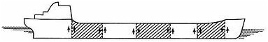
Hull Girder Longitudinal Bending Moment
The hull girder bending moment* resulting from the distribution of cargo, ship weight and buoyancy along the length of the vessel, in still water and wave.
STILL WATER SAGGING OR HOGGING
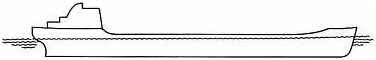
WAVE SAGGING
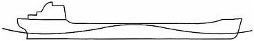
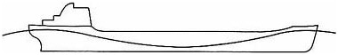
WAVE HOGGING
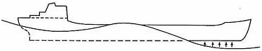
Slamming
The impact loads on the flat bottom forward due to pitching as shown below:
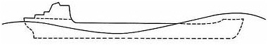
Green Water on Deck
The impact loads due to bow slamming and the effect of green water* on deck.
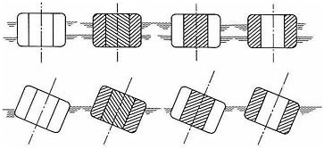
Liquid Cargo Sloshing
In partially filled tanks, the sloshing and impact loads of liquid cargo on bulkhead, shell and deck tank boundaries, resulting from the inertial reactions between the accelerated mass of the liquid and the ship structure when the ship is rolling and pitching in a seaway can be very large. These loads vary with the number of swash bulkheads and level of liquid in the tank. The next page shows the result of a recent ABS study. At 35% full, the sloshing pressure without swash bulkheads is [Figure B-1 (A)] 33,640 pressure per square foot (psf), [Figure B-1(B)] 8,060 psf with one swash bulkhead, and [Figure B-1(C)] 4,362 psf with two swash bulkheads. Without swash bulkheads, the sloshing pressure jumps from 33,640 psf to 68,073 psf when the liquid level is increased from 35% to 75% full [from Figure B-1(A) to Figure B-1(D)].
Thermal Loads
Thermal loads result from non-linear temperature differentials in ship structure, and have to be considered in the design of vessels carrying hot cargoes.
SCANTLINGS SELECTION
The design objectives of the structural optimization for the selection of scantlings and dimensions of structural members are the following:
Reduce steel weight—to save on cost of building material and loss of cargo
Simplify details and fabrication procedures—to save labor costs
Keep stresses and deflections within acceptable limits—to avoid structural problems later in service.
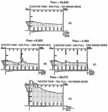
FIGURE B-1 Liquid Cargo Sloshing. Dynamic loads on tank boundaries due to rolling and pitching.
ENGINEERING ANALYSIS
As an alternative to using rule equations, the classification society rules permit use of scantlings obtained by systematic analysis based on sound engineering principles, provided they meet the overall safety and strength standards predicated by the rules.
This rule provision is normally utilized for the design of large tankers, whose structure and loads are too massive and complex to rely entirely on rule empirical equations. The normal practice is to base the tanker's design on engineering analysis, and to use rule equations only as a check, for guidance and control. The potential benefit from utilizing engineering analysis
is stress verification and rational distribution of steel, which results in steel weight optimization without sacrificing strength.
Ship Moment
The first step in the analysis consists of calculating the hull girder longitudinal vertical bending moment, for all anticipated loaded and ballast conditions. This calculation is based on the offsets describing the hull geometry, and on the lightship and cargo weight distribution. A computer program is utilized for this purpose, which in addition to the hull girder bending moment yields also the equilibrium draft and trim, as well as the hull girder shear forces and vertical deflections.
Ship Motion
The next step in the analysis is to calculate the vertical, lateral and torsional dynamic components of the hull girder bending moments, as well as the motions, point accelerations and pressure distribution along the vessel's length. A computer program based on two-dimensional, six-degree of freedom strip-theory, is used to calculate motions and loads for the vessel in arbitrary headings in long and short crested seas, combined with probabilistic considerations of statistical wave data normally measured in the North Atlantic.
3-D Global 3-D Finite Element Analysis (FEM)
The data obtained from ship moment and ship motion above are used to carry out a three-dimensional global FEM analysis for the entire vessel, or for a portion of the hull girder. This analysis gives the overall structural response in the form of element stresses and displacements.
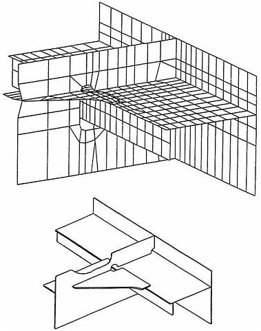
3-D Local Finite Element Analysis (FEM)
The three-dimensional fine mesh FEM analysis is used to obtain the detailed stress distribution in way of localized structural details of interest, such as the typical connection of side shell longitudinal to the web frame and transverse bulkhead shown in Figure B-2. The displacements from the 3-D global model, at the appropriate coincident nodes, are used as boundary conditions for the 3-D fine mesh models.
2-D FEM Local Analysis
The two-dimensional fine mesh FEM analysis is carried out for selective web frames, or other structural members, where precise distribution of stresses
is required. The use of fine mesh models permits the avoidance of localized high stresses and a better resolution of details.
Sloshing Analysis
This analysis is used to determine the dynamic loads on the tank boundaries from the motion of the fluid within the tank due to ship movements in a seaway.
Thermal Stress Analysis
This analysis provides the distortions and stresses in the hull structure induced by non-linear temperature differentials in vessels carrying hot cargoes.
Fatigue and Fracture Mechanic Analysis
Based on the combined effect of loading, material properties and flaw characteristics, this analysis predicts the service life of the structure, and determines the most effective inspection plan.
Vibration Analysis
This analysis is used to determine the extent of vibrations in the ship structure induced by the interaction of fluids, structure, machinery and propellers.


