Tactile Wayfinding in Transportation Settings for Travelers Who Are Blind or Visually Impaired: Volume 2: Guide (2025)
Chapter: 3 Transit Facility and Other Plaza-Type Applications
CHAPTER 3
Transit Facility and Other Plaza-Type Applications
TWSIs have a broad range of potential applications at transit facilities and in plaza-type applications to provide guidance for pedestrians with vision disabilities. At rail and bus transit stations, TWSIs can help to locate these focus areas:
- Boarding platform locations
- Boarding platform edges (DWSs are required at all platform edges raised above standard curb height that have no edge screens or guards, and at sidewalk-level or street-level rail platforms that have no edge screens or guards)
- Transit vehicle door opening locations
- Fare purchase, payment, or validation stations
- Faregates
- Stairs
- Elevators
- Escalators
- Agent booths
- Restrooms
- Entrance and exit locations
- Accessible pickup and drop-off locations
Plaza-type applications include open spaces intended for pedestrian travel with large areas that lack a detectable path to follow; TWSIs can help pedestrians with vision disabilities navigate where few or no detectable edges for the intended path can be provided. Examples of plaza-type applications include pedestrian malls, plazas, and shared streets where pedestrians and vehicles are allowed to mix.
Planning Process
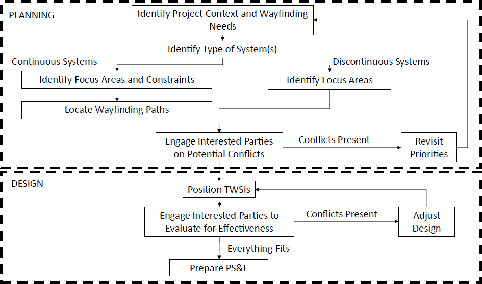
Figure 14 shows a flowchart of the planning and design process that can be used for transit facilities and open spaces. Pedestrians with visual impairments benefit when TWSIs in these areas are considered as an interconnected system. Advanced planning and engagement with interested parties to determine the best option among many possible TWSI system designs is also beneficial.
The planning and design process has two key characteristics:
- The process engages interested parties. At the outset and at key decision points along the way, interested parties should be consulted to help formulate the plan and evaluate its effectiveness.
- The process is iterative. At several steps along the way, the project team should engage interested parties and evaluate the effectiveness of the proposed wayfinding plan and any constraints that may reduce its effectiveness.
Identifying Project Context and Wayfinding Needs
Wayfinding needs for a transit setting or open space application can be addressed by answering a set of questions, dependent on the context of the project:
- What are the key focus areas the wayfinding system should connect or identify?
- Is the project in an urban or rural environment?
- Are there other existing edge treatments or detectable cues that provide wayfinding naturally?
- What is the most logical route between each focus area?
- Is the environment simple with a small number of possible focus areas, or are there many possible focus areas that need to be prioritized to prevent the network of connections from being confusing?
- Are there physical constraints—obstructions, horizontal or vertical changes in alignment, or other features—that may influence a path’s location?
Focus areas can be viewed at a range of scales. It is helpful to look initially at a macroscopic level where wayfinding between specific focus areas is considered. There may be more than one possible route to get between focus areas. However, one route is likely to be the shortest or most desirable.
Once these macroscopic needs are identified, a microscopic look is needed to focus on developing a tactile path serving each focus area, with consideration of how individual paths should or should not serve multiple focus areas. Engaging orientation and mobility specialists early in the planning and design process can be especially helpful. Orientation and mobility specialists may have valuable insights as to the key focus areas, the best routes between focus areas, the challenges along each potential route, and the treatments needed at each challenge.
Identifying the Type of System to Use
Tactile wayfinding systems can be designed as one of two types:
- Continuous system: provides a set of tactile indications that guides a person to all designated focus areas in the system, such as from station entrances to platform edges, including any
- intermediate stops. This type of system is most appropriate where transit platforms are wide enough to allow the path to be designated using TWSIs. It is also appropriate for plaza-type applications.
- Discontinuous system: provides localized tactile indications. This type of system is more suitable in space-constrained environments, such as narrow boarding platforms, where other detectable elements of the built environment can provide wayfinding guidance.
Continuous Systems
The first step in the planning process for a continuous system is to identify the key destinations. Travel between these destinations is typically bidirectional and thus needs to be able to serve pedestrians walking in both directions. Potential destinations for transit station applications were identified at the start of this chapter. For shared-space applications, destinations commonly include key entrances into the shared space and any significant points of interest in the shared space.
At each destination, the design team should identify a wayfinding terminal. This is a single point the wayfinding system extends from. For some key destinations, such as in front of elevator doors or a stairway, only one wayfinding terminal is likely possible—commonly centered in front of the destination. For other key destinations, such as a bank of ticket machines, faregates, and boarding locations, multiple destinations are possible. As a result, the design team has flexibility in selecting the wayfinding terminal and should consider how the wayfinding system connects overall. Consultation with orientation and mobility specialists may be helpful in identifying preferred wayfinding terminal locations.
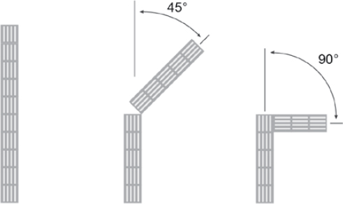
The wayfinding terminals are connected using wayfinding segments. These are initially located using straight lines. If one or more bends in the path are needed to connect wayfinding terminals, 90- and 45-degree bends are preferred, as illustrated in Figure 15. Research on the effectiveness of other angles or of curved segments is limited.
A minimum of 2 ft (0.6 m) of clearance should be provided on either side of the path centerline. It is desirable for there to be a clear path on one side of the TDI that is at least 3 ft wide (0.9 m) and preferably wider to provide a smoother surface for wheeled devices. Because some people prefer to walk next to the TDI path rather than on it, additional clearance is preferred where space permits.
A wayfinding junction of three or more wayfinding segments is called a choice point. A choice point is marked by a blank 3 × 3 ft (0.9 × 0.9 m) square. While some agencies in the United States and internationally have used truncated domes to mark these junctions, in the United States, truncated
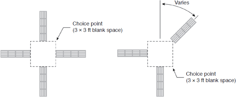
domes are recommended to be reserved to mark hazards. Testing performed during the development of this guide confirmed that pedestrians with vision disabilities can correctly identify junctions marked with blank squares (see Chapter 1). Although not tested in this research, it may be possible to represent the choice point more universally with a blank 3-ft-diameter circle. The use of a blank circle may allow more versatility for segments to intersect at angles other than 90 degrees.
TDI paths should be designed to have segments as long as possible between choice points to decrease the likelihood of confusion. Figure 16 illustrates the concept of a choice point.
It is sometimes necessary to break the wayfinding material along a segment due to a surface obstruction such as a junction box cover. When feasible, it is preferable to route wayfinding segments in such a way that minimizes these breaks, as each break can introduce uncertainty for pedestrians with vision disabilities.
Discontinuous Systems
Discontinuous systems are systems of TWSIs used in applications where a continuous system is impractical or unnecessary. Because of their discontinuous nature, these systems are intended to assist pedestrians with vision disabilities with the following tasks:
- Identifying potential hazards and guiding pedestrians past them
- Locating midblock crossing points and transit stops
- Locating crossing points in a shared space
- Aligning to cross and, in some cases, maintaining alignment while crossing
- Locating transit boarding doors
In discontinuous systems, wayfinding guidance between destinations is provided by other detectable elements of the built environment, such as walls, raised curbs, borders between pavement and grass or dirt, and similar features.
Design Process
Design principles for the use of tactile wayfinding treatments in transit stations and open spaces include the following (adapted from APTA 2020):
- Tactile wayfinding in transit stations should be continuous, without any interruptions; discontinuities can create confusion for pedestrians with vision disabilities.
- Tactile wayfinding should be used sparingly so it does not interfere with the detection of DWSs.
- Tactile wayfinding should have a consistent color that adequately contrasts with the surrounding materials.
- Priority routes should be emphasized, such as to boarding areas and platform entrances and exits. It may be too confusing to provide tactile wayfinding to every point of interest.
When developing a design that will use different TWSIs, DWSs should be positioned first because they have a critical and standardized warning function. PROWAG (36 CFR Part 1190) sections R205 and R305 provide specific guidance on the use of DWSs. DWSs should be positioned using the following principles:
- In transit applications, DWSs are used to mark the edges of transit platforms elevated above standard curb height that have no platform edge screens or guards, and the length of boarding and alighting areas of sidewalk- or street-level rail transit stops without edge screens or guards.
- For marking hazardous locations in open-space applications, DWSs should always be installed in pairs to mark the boundaries of the hazardous area. The analogy of open and closed parentheses may be useful in understanding their function.
If bicycle and pedestrian facilities are next to one another with no horizontal or vertical separation, TWDs should be used to mark the boundary between them.
After DWSs and TWDs have been positioned, TDIs can be positioned to provide guidance for any of the following purposes:
- Following a pedestrian access route
- Locating a transit stop or a crossing in a transit center or station
- Locating the crossing to a floating transit island
- Finding a transit door location
- Aligning to cross a street
TDIs are used in three basic configurations in transit and open-space applications:
- Guide bars, a 12-in.-wide (30.5 cm) strip used for navigation along a path. These are used in continuous systems along a wayfinding centerline in a transit station or open space. They may also be used in discontinuous systems to guide pedestrians past a facility not intended for pedestrian travel. In these cases, the alignment of the raised bars in the TDI strip are generally parallel to the direction of pedestrian travel.
- Sidewalk alert bars, a 24-in.-wide (61.0 cm) strip to locate crossing points of streets, separated bicycle facilities, rail tracks, or busways in or adjacent to a transit stop or station, or in a shared space. In this application, the TDI strip spans the width of the sidewalk, ending at the curbline beside or behind the end of the DWS marking the boundary between the pedestrian area and the vehicular area. The raised bars are placed parallel to the pedestrian direction of travel on approach along the sidewalk and perpendicular to the direction of travel across an associated crosswalk.
- Transit door location bars, a 24 × 36 in. (61.0 × 91.4 cm) or longer rectangle of TDI bars, with the bars typically parallel to the curbline or platform edge and with the shorter edge of the rectangle placed along the curbline or platform-edge DWS. Where space permits, a greater than 3 ft (0.9 m) length is more certain to be found by pedestrians with vision disabilities, especially those using guide dogs. Some transit agencies have installed the bars perpendicular to the curbline or platform edge, so people using mobility devices will not have to roll across the bars while entering or boarding a transit vehicle. However, a perpendicular orientation means people using mobility devices will roll across any bars encountered while traveling along the platform (i.e., bars marking the position of vehicle doors). Some transit agencies also install the bars slightly to the side of the intended door opening position to indicate where to
- wait, rather than installing the bars directly in front of the door opening position. Research on these alternative orientations and locations is limited.
Chapter 4 provides information on locating and marking at-grade street, bicycle lane, and rail crossings.
Potential Applications
This section presents a variety of potential TWSI applications in transit stations and other plaza-type applications. These examples are intended to illustrate some of the more commonly anticipated applications but are not intended to be exhaustive of all possible applications.
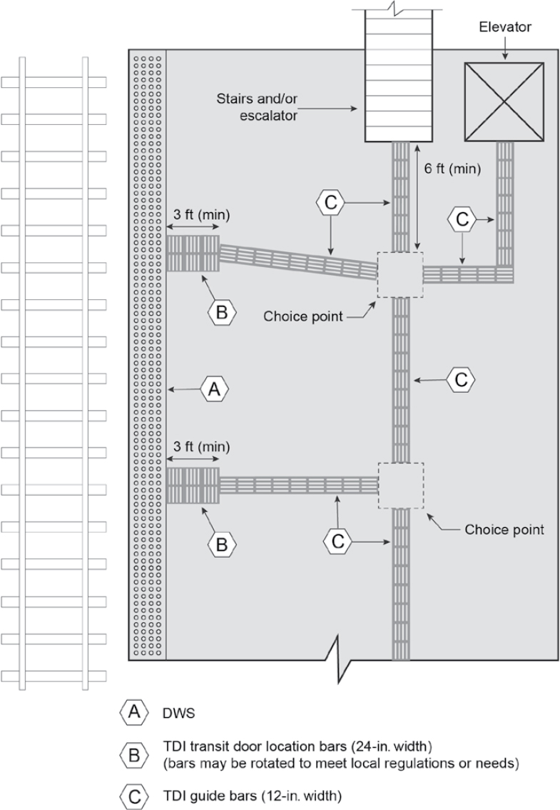
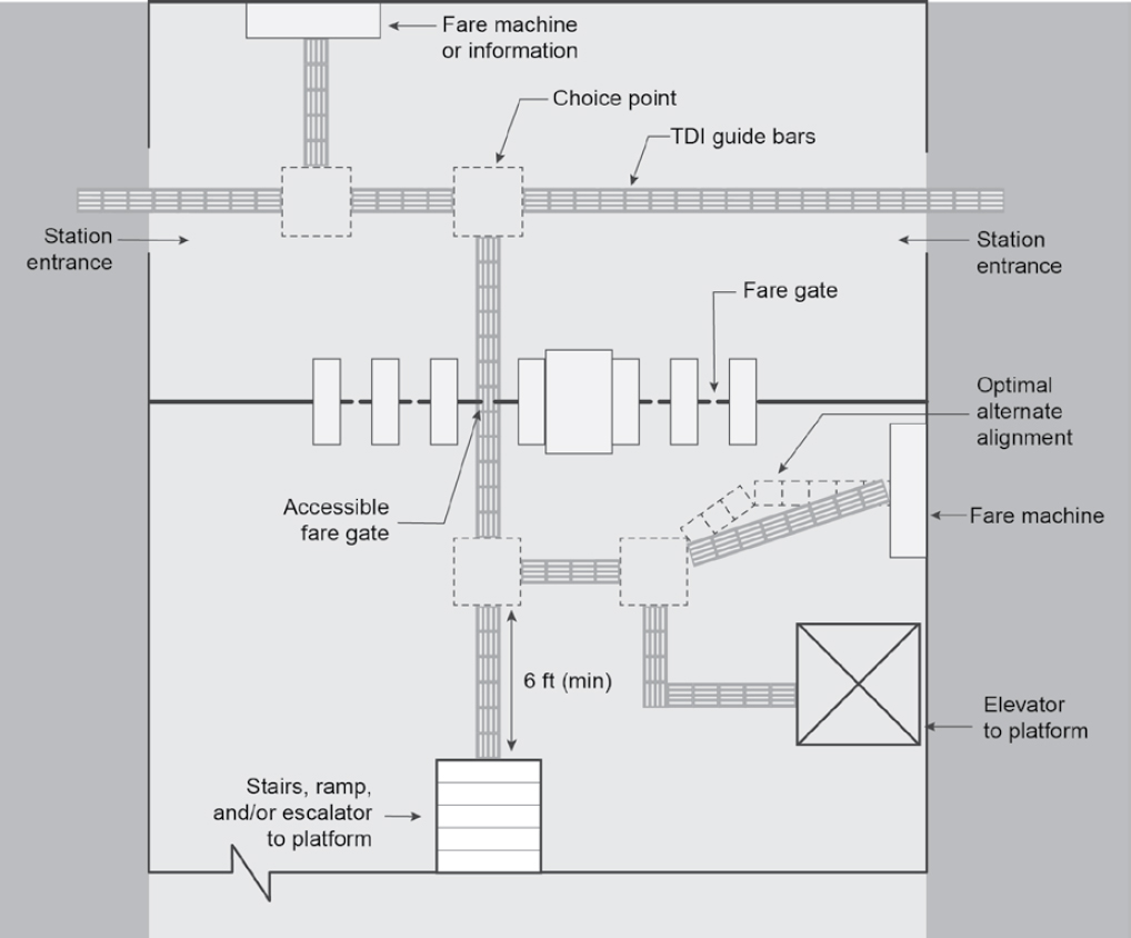
Transit Station Mezzanine
Figure 17 illustrates a generic transit station mezzanine area with fare machines, faregates, and access points to the boarding platform. These access points may be at the same elevation in the station area or may be separated in elevation by a combination of ramps, stairs, escalators, and elevators.
Boarding Platforms for Rail Transit
Boarding platforms for rail transit come in a variety of configurations:
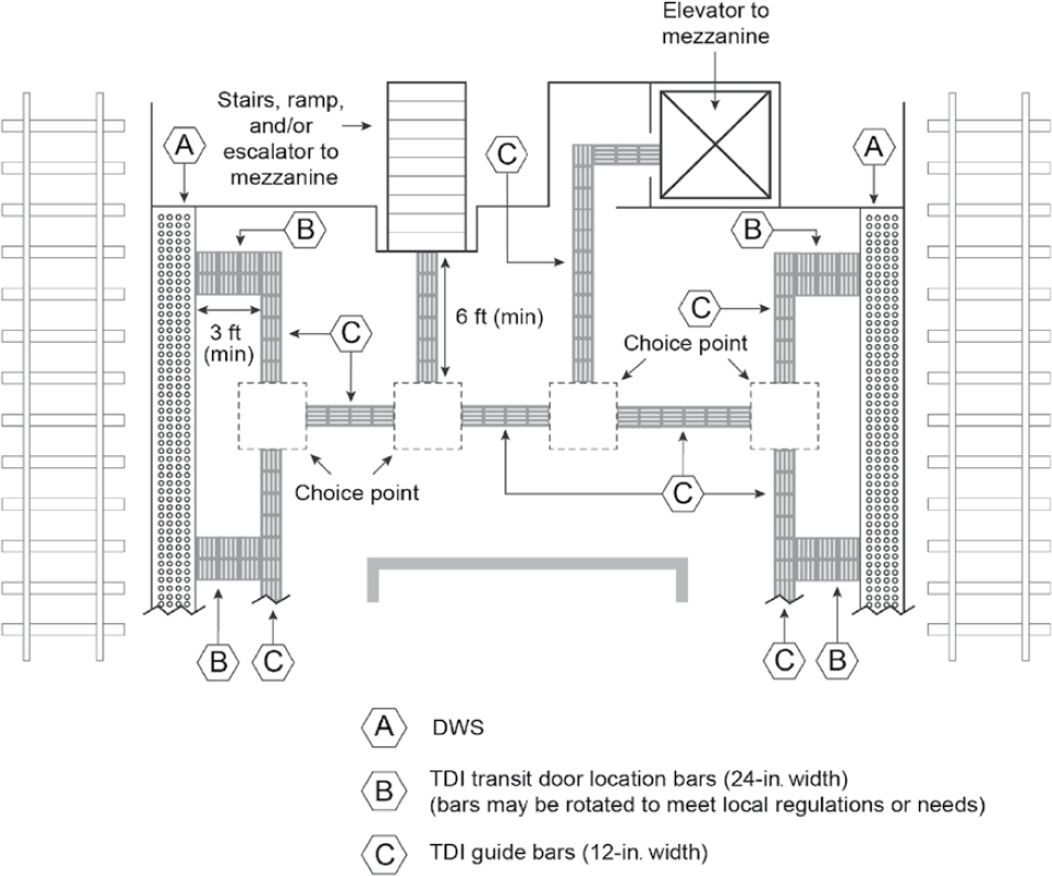
- Wide center platform: rail tracks on both sides of the platform and seating areas, information displays, support columns, or other features along the centerline of the platform. This configuration creates room for two separate defined paths for pedestrian travel adjacent to each track. Figure 18 illustrates this application.
- Narrow center platform: rail tracks on both sides of the platform and a single path for pedestrian travel between the rail tracks. Figure 19 illustrates this application.
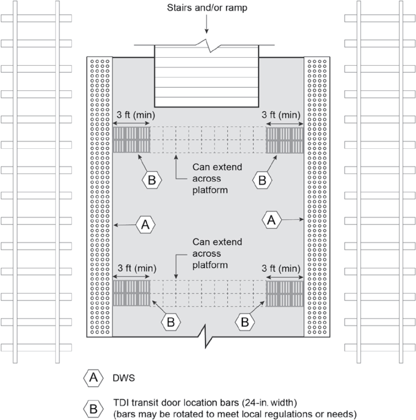
- Wide side platform: a rail track on only one side of the platform, with room for seating areas, information displays, support columns, or other features on the side of the platform opposite the track. This configuration creates space for a defined path for pedestrian travel adjacent to the rail track. Figure 20 illustrates this application.
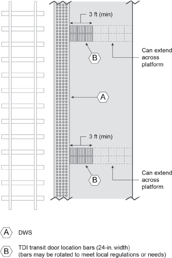
- Narrow side platform: a rail track on only one side of the platform, but without space for a defined pedestrian travel path adjacent to the rail. Figure 21 illustrates this application.
Boarding Platforms for Bus Transit
Boarding platforms for bus transit come in a variety of configurations:
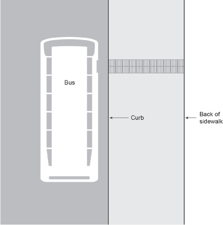
- Bus stop along sidewalk: a bus stop along a sidewalk, commonly near a pedestrian crossing. Figure 22 illustrates this application.
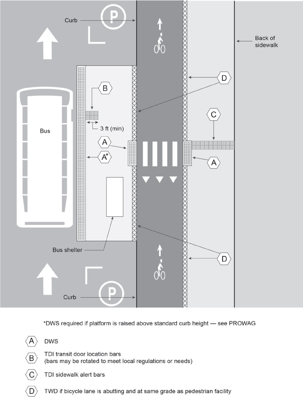
- Bus stop on floating transit island, separated from the sidewalk by a bicycle lane: Figure 23 illustrates this application. Note that a DWS is not required at the face of curb unless the curb height is greater than 6 in.
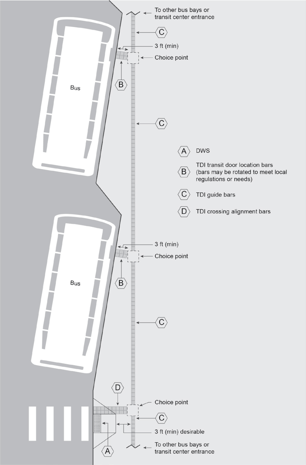
- Bus stop in transit center: multiple bus stops as part of a transit center, often with a wide platform to allow a continuous wayfinding system. Figure 24 illustrates this application.
It may be desirable to provide TDIs for locating both front and rear bus doors. Coordination with the transit agency is suggested to determine desired practice. Placement of TDIs for both front and rear doors may not be possible if the door spacing varies within the bus fleet using the bus stop.
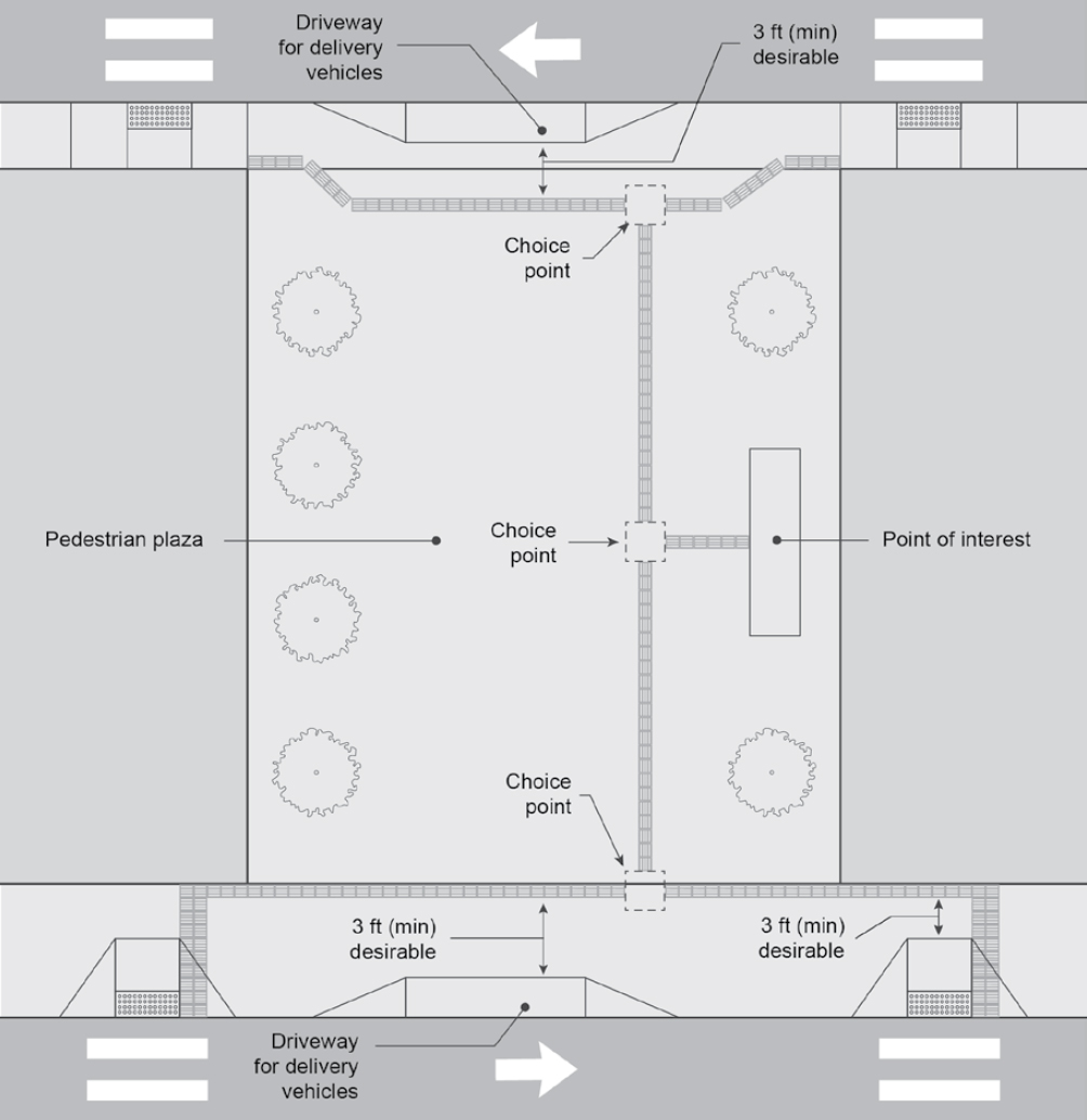
Other Plaza-Type Applications
Other plaza-type applications include pedestrian plazas, shared streets, and other locations where identifying appropriate paths for people with vision disabilities is beneficial. Figure 25 shows an example of TWSI applications in a pedestrian plaza. Orientation and mobility training encourages people to walk on the building side of a sidewalk away from the street, so TDIs should be located toward the building side to maximize the likelihood of detection (see Chapter 5 for further discussion).