Considerations for the Design and Construction of Bonded and Unbonded Post-Tensioned Concrete Bridge Elements (2025)
Chapter: 2 Literature and Specification Review
CHAPTER 2
Literature and Specification Review
2.1 Introduction
The following sections include a review of past research and current knowledge of the flexural, shear, and torsional behavior of post-tensioned members relevant to the current study. In addition, a review of current requirements in the AASHTO specifications is included to identify potential gaps in the specifications specifically related to the design of post-tensioned members with unbonded tendons or a combination of bonded/unbonded or internal/external tendons.
2.2 Flexural Strength
2.2.1 Members with Bonded Strands in Flexure
Prestressed concrete structures most commonly incorporate bonded strands in the United States (pretensioned or grouted post-tensioned strands). Because strands and concrete are bonded, an increase in loading beyond cracking in bonded prestressed members causes narrower cracks (compared to unbonded post-tensioning) and increases strand stress at localized crack locations. Stress increase in strands due to external loading can be calculated through a cross-sectional analysis using strain compatibility between the strands and concrete.
As an alternative to strain compatibility, the LRFD Bridge Design Specifications (BDS) (AASHTO 2020) provides Equation 5.6.3.1.1-1, reproduced here as Equation 2.1, to estimate the average stress in strands at nominal flexural capacity, fps. This equation can be used when the effective prestress is not less than half of the ultimate strength of the strands, fpu. Developed in the 1970s, the equation uses a simplified representation of the stress-strain behavior of strands to calculate stress from strains that develop at ultimate moment capacity (Loov 1988; Naaman 1985; Naaman 1986; Naaman and Harajli 1985).
| Equation 2.1 |
where:
| fps = | average stress in prestressing steel at the time for which the nominal resistance of member is required, in kilopounds per square in. (ksi) |
| fpu = | specified tensile strength of prestressing steel (ksi) |
| fpy = | yield strength of prestressing steel (ksi) |
| c = | distance from the extreme compression fiber to the neutral axis (in.) |
| dp = | distance from extreme compression fiber to the centroid of the prestressing force (in.) |
Both strain compatibility and the approximate LRFD BDS equation define the flexural behavior of prestressed concrete sections well, as shown by tests in the literature.
2.2.2 Members with Unbonded Internal Strands in Flexure
The behavior of prestressed concrete sections with unbonded internal strands under flexure is not as well understood as the behavior of sections with bonded strands. Due to lack of bond between strands and concrete, the change of strain in the strands is not equal to the change of strain in the adjacent concrete, but rather equal to the average change of strain in the concrete surrounding the strands. In other words, the behavior of prestressed concrete members with unbonded internal strands is dependent on displacement of the member as a whole as well as the flexural failure mechanism. The increase in stress in unbonded strands due to loading is expected to be smaller than the increase in stress for bonded strands.
2.2.2.1 Experimental Studies
Many experimental studies have been conducted to identify the parameters that affect the flexural behavior of prestressed concrete beams with internal unbonded strands as summarized in Table 2.1. Maguire et al. (2017) compiled a database of more than 250 tests on unbonded prestressed members, including members with internal strands, members with external strands, simply supported members, and continuous members. Pannell (1969), Tam and Pannell (1976), and Ozkul et al. (2008) tested 67 simply supported beams with unbonded internal strands. They demonstrated that the effective prestress in strands, fpe, had a significant influence on the flexural strength and failure mechanism. Members with higher effective prestress developed distributed cracks as opposed to a few large cracks. Tam and Pannell (1976) defined an effective prestressed force index (qe) as the ratio of the effective prestressed force of strands to the ultimate compressive force of concrete. Beams with high values of fpe (qe > 0.3) develop multiple cracks in the tension zone, similar to the behavior of bonded prestressed concrete beams, whereas beams with low values of fpe (qe < 0.15) developed two or three major cracks in the maximum moment region. The plastic rotation capacity of beams with the low values of fpe was shown to be greater than those with the relatively high values of fpe. Furthermore, the stress increment in strands, Δfps, depended on the ratio of effective stress to ultimate strength of the strands.
The effects of the amount of prestressed unbonded reinforcement and supplementary nonprestressed bonded reinforcement on flexural behavior have been investigated by several researchers (Burns et al. 1991; Campbell and Chouinard 1991; Chakrabarti 1995; Du and Tao 1985; Harajli and Kanj 1992; Janney et al. 1956; Mattock et al. 1971; Ozkul et al. 2008; Pannell 1969; Tam and Pannell 1976; Zhou and Zheng 2014). Beams without additional nonprestressed bonded reinforcement tended to fail by developing one or two major cracks, while beams with additional nonprestressed bonded reinforcement developed multiple cracks before failure. The supplementary nonprestressed bonded reinforcement increased the ultimate flexural strength of the beams. Significant plastic deformation (ductility) before failure was observed regardless of the amount of nonprestressed reinforcement. In addition, fps decreased with additional nonprestressed reinforcement because the tensile force was shared between prestressed strands and nonprestressed reinforcement.
Observations based on experimental data indicated that increasing the span-to-depth ratio from 10 to 50 reduced fps when other experimental parameters were kept constant (Burns et al. 1991; Chakrabarti et al. 1994; Harajli and Kanj 1992; Ozkul et al. 2008; Tam and Pannell 1976; Zhou and Zheng 2014). Harajli and Hijazi (1991) demonstrated that the span-to-depth ratio affected the cracking pattern, including diagonal tension cracks. The increase of the span-to-depth ratio decreased the spread of plasticity over the length of the flexural member at failure. The span-to-depth ratio and loading location may influence stress in strands at nominal capacity
Table 2.1. Summary of flexural tests on members with unbonded internal tendons.
| Reference | Support Type | No. of Load Points Across Span | Span/Depth Ratio | Beam Type | P/S Profile | Area of P/S Aps (in.2) | Area of Mild Steel As (in.2) | As/Aps | fpe/fpu | f′c (ksi) | No. of Specimens |
|---|---|---|---|---|---|---|---|---|---|---|---|
| Janney et al. (1956) | Simply supported | 2 | 13 | Rec. | Straight | 0.08–0.48 | 0, 0.4 | 0-5 | 0.4–0.5 | 4.8–5.8 | 8 |
| Pannell (1969) | Simply supported | 1 | 12–40 | Rec. | Straight | 0.12–0.48 | 0 | 0 | 0.2–0.7 | 4.5–6.2 | 38 |
| Gebre-Michael (1970) | Continuous | N/A | 45 | Slab | N/A | 0.18 | 0.2 | 0.9, 0.96 | 0.6–0.7 | 5.2, 5.5 | 4 |
| Hemakom (1970) | Continuous | N/A | 45 | Slab | N/A | 0.4–0.8 | 0.33 | 0.4-0.83 | 0.67 | 4.2–6.1 | 6 |
| Chen (1971) | Continuous | N/A | 30 | Slab | N/A | 0.2–0.3 | 0.17, 0.29 | 0.72, 0.96 | 0.6 | 5.3, 6.8 | 5 |
| Burns and Hemakom (1977) | Continuous | uniform | 22 | Slab | Draped | 0.11 | 0.2, 0.35 | 1.83, 3.21 | 0.6 | 4.7 | 6 |
| Mattock et al. (1971) | Continuous | 4 | 34 | T | Draped | 0.4 | 0.1, 0.45 | 0.25–1.12 | 0.65 | 4 | 2 |
| Mattock et al. (1971) | Simply supported | 4 | 34 | Rec. T | Draped | 0.31 | 0.1–0.55 | 0.33–1.8 | 0.7 | 4 | 5 |
| Tam and Pannell (1976) | Simply supported | 1 | 18–43 | Rec. | - | 0.12–0.36 | 0.24–0.48 | 0.67–4.03 | 0.4–0.6 | 6–8.4 | 8 |
| Burns et al. (1978) | Continuous | uniform | 53 | Slab | Draped | 0.6, 0.8 | 0.2, 0.4 | 0.26, 1.67 | 0.6 | 4.7, 5.2 | 6 |
| Cooke et al. (1981) | Simply supported | 2 | 20–40 | Rec. | Straight | 0.18, 0.43 | 0 | 0 | 0.65,0.66 | 4.4–5.0 | 9 |
| Du and Tao (1985) | Simply supported | 2 | 19 | Rec. | Straight | 0.06–0.24 | 0.24–1.25 | 1–21 | 0.4–0.5 | 4.4–7.1 | 20 |
| Campbell and Chouinard (1991) | Simply supported | 2 | 15 | Rec. | Straight | 0.23 | 0–1.55 | 0–6.76 | 0.6 | 4.4-5.5 | 6 |
| Burns et al. (1991) | Continuous | uniform | 16, 27 | Rec. | Draped | 0.46 | 0.39, 0.61 | 0.85, 1.34 | 0.75 | 5 | 2 (3)* |
| Harajli and Kanj (1991) | Simply supported | 1, 2 | 8-19 | Rec. | Straight | 0.03–0.18 | 0.1–0.62 | 0.56–22 | 0.6 | 5.2-6.8 | 26 |
| Gauvreau (1992) | Simply supported | 1, 9 | 14 | I | Draped | 0.42, 0.84 | 1.9–3.7 | 2–9 | 0.6–0.7 | 5.8–10.2 | 7 |
| Chakrabarti (1995) | Simply supported | 2 | 17–55 | Rec. T | Draped | 0.04–0.18 | 0–0.8 | 0–23 | 0.4–0.7 | 4.9–8.7 | 33 |
| Mutsuyoshi et al. (1995) | Simply supported | 2 | 21 | T | Draped | 0.4 | 0.4 | 0.97 | 0.45 | 5.7 | 1 |
| Nishikawa et al. (2000) | Simply supported | 2 | 19 | I | Straight | 0.6 | 0.4 | 0.77 | 0.47 | 7.4 | 1 |
| Ozkul et al. (2008) | Simply supported | 2 | 8-18 | Rec. T | Straight | 0.08–0.31 | 0-0.62 | 0-8 | 0.6–0.7 | 6.7–13.1 | 21 |
| Vu et al. (2010) | Simply supported | 2 | 19 | Rec. | Straight | 0.08 | 0.09 | 1.1 | 0.7 | 6.5 | 2 |
| Zhou and Zheng (2014) | Continuous | 1 | 11-16 | Rec. | Draped | 0.09–0.61 | 0.62-1.53 | 1-17 | 0.35–0.6 | 6.9 | 16 |
| Six (2015) | Continuous | 1 | 45 | Slab | Draped | 0.15 | 0.1, 0.2 | 0.64–1.44 | 0.56–0.6 | 5 5 | 4 |
| Maguire et al. (2016) | Continuous | 4 | 32 | Slab | Draped | 0.15 | 0.22 | 1.44 | 0.68 | 6.5 | 3 |
P/S = prestressing strand; fpe = effective prestress in strands; fpu = specified tensile strength of prestressing steel; f′c = concrete strength; N/A = not available; Rec. = rectangular
*One specimen was tested twice, with a point load applied on either side of midspan.
(Alkhairi and Naaman 1993; Harajli 1990; Naaman et al. 2002; Ozkul et al. 2008), although there is not a strong consensus on the effects of these parameters in the literature.
Chakrabarti (1995) and Ozkul et al. (2008) demonstrated that varying concrete strength from 5 ksi to 13 ksi had a marginal impact on the flexural capacity of prestressed beams with unbonded strands. Experimental research conducted by Harajli and Kanj (1992) showed that load configuration, which is expected to affect the length of plastic regions, was not a critical parameter in determining Δfps in unbonded strands. The results of this investigation conflicted with earlier studies by Loov (1987) and Harajli and Hijazi (1991).
The majority of beams tested in the literature were simply supported; however, research has also been conducted on continuous beams. Mattock et al. (1971) and Burns et al. (1991) examined the flexural behavior of continuous beams with internal unbonded strands. They generally concluded that the actual flexural strength of continuous beams with internal unbonded tendons exceeded the flexural capacity predicted by the American Concrete Institute’s (ACI) ACI 318-63 (ACI 1963) due to redistribution of moments and high moment capacities at the center support. The relationship between Δfps and midspan deflection was nonlinear in two-span beams. For simply supported beams, this relationship was linear (Zhou and Zheng 2014). In contrast, for slabs, most specimens were continuous as indicated in Table 2.1. Maguire et al. (2016) tested four continuous slab specimens and concluded that predictions of ACI (1963), AASHTO (2010), and Naaman and Alkhairi (1991) for stress increase were conservative even though most equations were developed and calibrated using data on simply supported members.
2.2.2.2 Analytical Approaches
Due to the lack of strain compatibility between unbonded strands and concrete, numerous displacement-compatibility analyses for global behavior of beams with unbonded internal strands in flexure have been proposed (Allouche et al. 1998; Harajli 1990; Kim and Lee 2012; Mattock et al. 1971; Ozkul et al. 2008; Pannell 1969; Tam and Pannell 1976; Warwaruk et al. 1962). These methods have varying levels of complexity and accuracy in predicting the response.
Vu et al. (2010) proposed a displacement-compatibility analysis for beams with internal unbonded strands under both service and ultimate flexural loading. Monotonic and repeated load effects were included. The analysis was able to predict the overall lengthening of unbonded strands at all loading stages: cracking, serviceability, and ultimate. The proposed method agreed well with the two specimens in their study (Table 2.1) in terms of global behavior and crack propagation.
As an alternative to a displacement-compatibility analysis, the LRFD BDS (AASHTO 2020) provides Equation 5.6.3.1.2-1 (reproduced here as Equation 2.2) to estimate the average stress in strands at nominal flexural capacity. This equation was adopted first into the AASHTO LRFD specifications in 1998 based on research by MacGregor (1989). The equation was developed after observing that stresses in strands do not increase significantly before cracking, rotation at midspan hinges is approximately twice the rotation at supports, and ultimate strength is achieved after a collapse mechanism is formed (Roberts-Wollmann et al. 2005). LRFD BDS indicates that a first estimate of fps can be taken as fpe+15 ksi (AASHTO 2020).
| Equation 2.2 |
where:
| fps = | average stress in prestressing steel at the time for which the nominal resistance of member is required (ksi) |
| fpe = | effective stress in prestressing steel after losses (ksi) |
| fpy = | yield strength of prestressing steel (ksi) |
| dp = | distance from extreme compression fiber to the centroid of the prestressing force (in.) |
| c = | distance from the extreme compression fiber to the neutral axis (in.) |
| le = | effective tendon length (in.) |
Equations to predict Δfps for unbonded strands at flexural failure have been developed. A summary of Δfps equations, including the ones in the LRFD BDS (2020) and ACI 318-19 (ACI 2019), is given in Table 2.2. Some of these equations were proposed based on the collapse mechanism and change in length of strands within plastic hinge locations, calculated using geometry at flexural
Table 2.2. Summary of proposed ∆fps equations for unbonded internal strands.
| Reference | ∆fps (ksi) | Notes |
|---|---|---|
| AASHTO (2020) based on MacGregor (1989) | ; | |
| ACI 318-19 (2019) | ||
| Warwaruk et al. (1962) | ||
| Pannell (1969) | ||
| Tam and Pannell (1976) | ||
| Du and Tao (1985) | ||
| Kordina and Hegger (1987) | ||
| Harajli (1990) | ||
| Naaman and Alkhairi (1991) and Naaman et al. (2002) | ||
| Lee et al. (1999) | ||
| Au and Du (2004) | ||
| Ozkul et al. (2008) | ||
| He and Liu (2010) | * η, ϕ: parameters determined based on load type and strand profile | |
| Harajli (2011) | ||
| Harajli (2012) | ||
| Maguire et al. (2017) | ψ = 13.70 for simply supported members with internal strands ψ = 18.88 for simply supported members with external strands ψ = 14.02 for continuous members with internal strands ψ = 18.46 for continuous members with external strands |
Note: For definitions of symbols used in Table 2.2, refer to Table R.1.
failure (Du and Tao 1985; Harajli 1990; Harajli 2011; Kordina and Hegger 1987; Ozkul et al. 2008; Pannell 1969; Tam and Pannell 1976). A model that utilizes a bond reduction coefficient, Ωu, which unifies predictions of Δfps for bonded (Ωu = 1.0) and unbonded strands has also been investigated (He and Liu 2010; Naaman and Alkhairi 1991). Others have proposed empirical equations (Warwaruk et al. 1962) or suggested modifications to ACI 318. Maguire et al. (2017) suggested a modified version of the LRFD BDS equation with a modification factor to predict the increase in strand stress. The modification factors recommended for continuous and simply supported members were very similar, indicating similar behavior. However, the factors were significantly different for members with internal strands and for members with external strands. The study also concluded that the LRFD BDS equation predicted the behavior of unbonded members conservatively but with poor precision.
2.2.2.3 Calculation of Strand Stresses at Failure
To provide an idea of the level of accuracy and conservatism provided by the LRFD BDS (AASHTO 2020) equation (Equation 2.2), Figure 2.1 shows a comparison of Δfps (stress at failure minus the effective stress) as calculated according to the LRFD BDS and as measured by the 233 tests summarized in Table 2.1. The tests were included in the comparison if the values of Δfps were available [data was not available for one specimen from Janney et al. (1956) and six specimens from Burns and Hemakom (1977)]. The 45-degree line indicates perfect correlation between the calculated values and the test data. The mean of the ratios of stress values measured by the experiments to stresses estimated by the equation and the corresponding coefficient of variation (CV) are 1.75 and 0.69, respectively. Although most calculated Δfps values are conservative (above the 45-degree line), there is a large scatter in the data.
2.2.3 Members with Unbonded External Strands in Flexure
The flexural behavior of concrete girders with unbonded external strands has generally been considered similar to that of concrete members with unbonded internal strands. The parameters that have an influence on Δfps of internal unbonded strands, such as span-to-depth ratio, loading configuration, amount of nonprestressed reinforcement, and effective prestress, also affect Δfps of external strands. Experimental research on unbonded strands is summarized in Table 2.3. The LRFD BDS

Table 2.3. Summary of flexural tests on members with unbonded external strands.
| Reference | Support Type | No. of Load Points Across a Span | Span/Depth Ratio | Beam Type | Number of Deviators | Area of P/S Aps (in.2) | Area of Mild Steel As (in.2) | As/Aps | fpe/fpu | f′c (ksi) | No. of Specimens |
|---|---|---|---|---|---|---|---|---|---|---|---|
| Zhang et al. (1993) | Simply Supported | 1, 2 | 13 | T | 0, 2 | 0.6, 1.52 | 0.2–0.6 | 0.1–1.0 | 0.3–0.5 | 7.2–7.6 | 7 |
| Mutsuyoshi et al. (1995) | Simply Supported | 2 | 21 | T | 2 | 0.43 | 0.37 | 0.85 | 0.49 | 5.7 | 3 |
| Yaginuma (1995) | Simply Supported | 2 | 17, 25 | Rec. | 0, 2 | 0.2–1.29 | 0.2–2 | 0.5–3.8 | 0.3–0.5 | 5–6 | 9 |
| Aravinthan et al. (1995) | Continuous | 2 | 18 | T | 4 | 0.3 | 0.35 | 1.2 | 0.57 | 5–6 | 4 |
| Tan and Ng (1997) | Simply Supported | 2 | 13, 17 | T | 0–2 | 0.16, 0.29 | 0.62 | 2.1, 4.0 | 0.7 | 4–5 | 6 |
| Nishikawa et al. (2000) | Simply Supported | 2 | 19 | T | 2 | 0.58 | 0.44, 1.23 | 0.8, 2.1 | 0.7–0.9 | 7–8 | 4 |
| Tan et al. (2001) | Simply Supported | 2 | 23 | T | 0, 1 | 0.24–0.31 | 0.62 | 2, 2.7 | 0.4–0.5 | 4.0–5.4 | 4 |
| Aparicio et al. (2002) | Simply Supported Continuous | 2 | 12 | Box | 2 | 0.8-1.7 | 0,1.09 | 0–1.3 | 0.5–0.8 | 5 | 6 |
| Harajli et al. (2002) | Continuous | 1 | 10–17 | Rec. | 1 | 0.06–0.12 | 0.09–0.24 | 0.7–6 | 0.5-0.6 | 5.3–6.1 | 8 |
| Ng (2003) | Simply Supported | 2 | 6–30 | T | 0-2 | 0.17, 0.31 | 0.62 | 2, 3.7 | 0.4 | 3.8–5 | 12 |
| Sivaleepunth et al. (2006) | Simply Supported | 2 | 15 | T | 2 | 0.44 | 0.62 | 1.4 | 0.5 | 8 | 3 |
| Tan and Tjandra (2007) | Continuous | 2 | 11–14 | Rec. | 2, 3 | 0.17 | 0.62 | 3.6 | 0.5 | 4.4 | 6 |
| Decheng (2009) | Continuous | 2 | 12–13 | Rec. T | 1, 2 | 0.17, 0.3 | 0.63 | 2, 3.7 | 0.5–0.6 | 4.9–6.6 | 6 |
| Yoo and Ha (2010) | Simply Supported | 1, 2 | 10–20 | Rec. T | 0-2 | 0.3–1.29 | 0.3-2.17 | 0.3–2.9 | 0.3–0.7 | 4.5–6.6 | 19 |
| Sritharan et al. (2019) | Simply Supported | 1 | 12–22 | Bulb Tee | 2 | 2–3 | 0 | 0 | 0.7–0.8 | 8.3–9.4 | 3 |
Note: P/S = prestressing strand; fpe = effective prestress in strands; fpu = specified tensile strength of prestressing steel; f′c = concrete strength; N/A = not available; Rec. = rectangular
provides the same design equation, derived from the study performed by MacGregor (1989), for calculating the stress increase for both internal and external unbonded strands (AASHTO 2020). However, external strands are only in contact with concrete at deviators and anchorages. Under loading, strands are relatively free to move with respect to concrete sections in between anchorages and/or deviators. The variation in the eccentricity of external strands under flexural loading, called second-order effects, distinguishes the behavior of externally and internally prestressed unbonded members (Harajli et al. 1999).
2.2.3.1 Experimental Studies
Several experimental and analytical studies (Aparicio et al. 2002; Aravinthan et al. 1995; Decheng 2009; Harajli et al. 2002; Mutsuyoshi et al. 1995; Ng and Tan 2006b; Nishikawa et al. 2000; Sivaleepunth et al. 2006; Tan et al. 2001; Tan and Ng 1997; Tan and Tjandra 2007; Yaginuma 1995; Yoo and Ha 2010; Zhang et al. 1993) concluded that neglecting second-order effects led to an overestimation of both the ultimate stress increase in the strands and flexural capacity. These studies also found that the number of deviators, configuration of deviators, span-to-depth ratio, and loading configuration had a significant influence on second-order effects. External undeviated tendons developed lower stresses at flexural failure compared to external deviated or internal unbonded strands. This resulted in the flexural capacity of beams with external undeviated tendons being smaller than the capacity of beams with external deviated strands.
Sritharan et al. (2019) tested three segmental girders with unbonded external strands under three-point bending. Two of these specimens did not meet the minimum reinforcement requirement of LRFD BDS (AASHTO 2020). The span-to-depth ratio of the specimens varied between 12 to 22. The ratio of moment capacity to cracking moment varied in the range of 1.06 and 1.44.
2.2.3.2 Analytical Approaches
Harajli (2012), Lee et al. (1999), and Naaman et al. (2002) proposed design equations to calculate Δfps for unbonded internal and external strands. These equations are given in Table 2.2 as they were developed to be suitable for both internal and external unbonded strands. Further work has analytically shown that the span-to-depth ratio and deviator configuration are closely related to second-order effects, and it was concluded that these parameters should be considered for the calculation of Δfps (Lou et al. 2013; Lou et al. 2012).
Equations for Δfps specifically developed for unbonded external strands, based on experimental and analytical investigations, are presented in Table 2.4. These equations include reduction coefficients ks (Ng 2003; Ng and Tan 2006a) and Rs (He and Liu 2010). Through statistical analysis, Maguire et al. (2017) proposed a “scaled plastic hinge” modification factor, ψ, applied to Δfps for unbonded external strands, as provided in Table 2.2.
Ng and Tan (2006a), Dall’Asta et al. (2007), and Peng et al. (2018) have suggested simplified analysis methods following principles of displacement compatibility to determine the moment-displacement relationship and capacity of beams with unbonded external strands.
2.2.3.3 Calculation of Strand Stresses at Failure
Figure 2.2 shows a comparison of Δfps (stress at failure minus the effective stress) as calculated according to the LRFD BDS (AASHTO 2020) equation (Equation 2.2) and as measured by 96 tests described in Table 2.3. The tests for which Δfps was reported were selected for the comparison [data was not available for three specimens from Sritharan et al. (2019) and one specimen from Decheng (2009)]. The mean of the ratios of stress values from tests to calculated values and the corresponding CV are 1.33 and 0.59, respectively. The predictions of Δfps for simply supported beams exhibit significant scatter with the number of conservative predictions similar to the number of unconservative ones. The predictions of Δfps for continuous beams, however, are mostly conservative (above the 45-degree line).
2.2.4 Members with Both Bonded and Unbonded Strands in Flexure
2.2.4.1 Experimental Studies
Table 2.5 summarizes experimental studies of concrete members with both bonded and unbonded strands. Tests in the literature cover a relatively wide range of ratios of bonded strand area to total strand area (0.2–0.8).
A study funded by the Florida DOT (Brenkus et al. 2017a; Brenkus et al. 2017b; Brenkus et al. 2019) included tests on two AASHTO I-beams with a combination of internal bonded and
Table 2.4. Summary of proposed ∆fps equations for unbonded external strands.
| Reference | Δfps (ksi) | Notes |
|---|---|---|
| Ng and Tan (2006a) | ||
| He and Liu (2010) | ||
| * η, ϕ: parameters determined based on load type and strand profile |
Note: For definitions of symbols used in Table 2.4, refer to Table R.2.
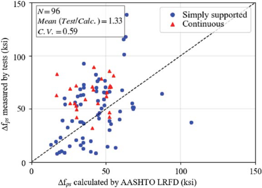
Table 2.5. Summary of flexural tests on members with both bonded and unbonded strands.
| Reference | Support Type | No. of Load Points Across a Span | Span/Depth Ratio | Beam Type | Area of Bonded P/S Apsb (in.2) | Unbonded Strands Type | Area of Unbonded P/S Apsu (in.2) | Apsb/Atotal | Unbonded fpe/fpu | Concrete Strength f′c (ksi) | No. of Specimens |
|---|---|---|---|---|---|---|---|---|---|---|---|
| Mutsuyoshi et al. (1995) | Simply Supported | 2 | 21 | T | 0.14 | External | 0.29 | 0.3 | 0.6 | 6 | 1 |
| Aravinthan et al. (1995) | Continuous | 2 | 18 | T | 0.11 | External | 0.22 | 0.3 | 0.4 | 6 | 1 |
| Kosa et al. (1997) | Simply Supported | 2 | 11 | I | 0.17–0.64 | External | 0.17–0.65 | 0.2–0.8 | 0.5 | 7–9 | 4 |
| Aravinthan et al. (2005) | Simply Supported Continuous | 1, 2 | 7-12 | Rec. | 0.29, 0.32 | External | 0.11 | 0.7 | 0.2 | 8-10 | 9 |
| Yoo (2010) | Simply Supported | 2 | 8 | Rec. | 1.29 | External | 0.61 | 0.7 | 0.4 | 6 | 3 |
| Yuan et al. (2015) | Simply Supported | 2 | 5 | Box | 0.9, 1.3 | External | 0.07, 0.13 | 0.5, 0.8 | 0.65 | 5 | 2 |
| Brenkus et al. (2017b) and Brenkus et al. (2019) | Simply Supported | 1, 2 | 10 | I | 0.65 | Internal | 2.6 | 0.2 | 0.5, 0.6 | 10, 13 | 2 |
| Brenkus et al. (2017a) | Simply Supported | 2 | 10 | I | 0.65 | External | 2.6 | 0.2 | 0.7 | 10, 13 | 2 |
| Abu-Obeidah (2017) | Simply Supported | 2 | 15,16 | T | 0.09–0.15 | Internal | 0.09–0.15 | 0.4,0.5 | 0.5–0.7 | 12 | 4 |
| Abu-Saibia (2018) | Continuous | 2 | 15,16 | T, I | 0.06 | Internal | 0.06 | 0.5 | 0.6–0.7 | 10–12 | 8 |
| Consolazio et al. (2022) | Simply Supported Overhang | 1 | 15-24 | I | 0.8–2.6 | Internal | 0.8–4.8 | 0.2-0.6 | 0.6–0.7 | 13–14 | 7 |
Note: P/S = prestressing strand; fpe = effective prestress in strands; fpu = specified tensile strength of prestressing steel; Rec. = rectangular
internal unbonded strands and two AASHTO I-beams with a combination of internal bonded and external unbonded strands under three-point and four-point bending. In these specimens, the area of unbonded strands was four times the area of bonded strands. The flexural strengths of the two beams with both internal bonded and internal unbonded strands were 93% and 98%, respectively, of the values calculated using the simplified method of the LRFD BDS (AASHTO 2020). Failure occurred due to rupture of the bonded strands. The specimen with internal bonded and internal unbonded strands tested under three-point loading had a smaller displacement ductility compared to the specimen tested under four-point loading. The specimen tested under three-point loading also had a smaller displacement ductility compared to a control case (also with three-point loading) where all strands were bonded. The flexural strengths of the two beams with internal bonded and external unbonded strands were 126% and 106%, respectively, of the values calculated using the simplified approach of the LRFD BDS (AASHTO 2020).
Aravinthan et al. (2005) and Yoo and Ha (2010) experimentally investigated a total of 11 rectangular beams with a combination of internal bonded and external unbonded strands. The main variables were the tendon eccentricity of external strands (at midspan and at the center support) and the loading pattern (symmetric vs asymmetric) of the two-span continuous beams (Aravinthan et al. 2005). The tendon eccentricity of external strands ranged from 15 to 25 in. at midspan and from 0 to 20 in. at the center support. It was concluded that high eccentricity within the tested range did not affect flexural behavior in either elastic or post-elastic loading ranges. The member tested under symmetric loading had nearly a 20% greater ultimate flexural capacity than the companion specimen tested under asymmetric loading. Yoo and Ha (2010) observed that beams with both internal bonded and external unbonded strands had compression and local failures under four-point bending.
Yuan et al. (2015) tested two segmental box girders with a combination of internal bonded and external unbonded strands under four-point bending. The ratios of bonded to total strands were 0.5 and 0.8. The bonded strand ratio had a major influence on the failure behavior of the tested beams. A higher ratio of internal bonded strands led to a greater load capacity.
A recent study funded by the Florida DOT (Consolazio et al. 2022) included tests on seven AASHTO Type II beams with a combination of internal bonded and unbonded strands. Four specimens were simply supported, while three specimens included overhangs to produce negative moment. The results of full-scale testing showed that increasing the ratio of unbonded strand area to total strand area resulted in lower flexural strengths and greater variability in the accuracy of the simplified method presented in the LRFD BDS (AASHTO 2020). The flexural strength of beams that failed in positive and negative bending decreased as the ratio of unbonded strand area to total strand area increased.
2.2.4.2 Analytical Approaches
The LRFD BDS (AASHTO 2020) provides two methods for analyzing members with bonded and unbonded tendons. In the detailed method, a combination of strain-compatibility and displacement-compatibility approaches is used. The specifications also allow a simplified method in which the bonded strand stress is calculated using Equation 2.1, and the unbonded strand stress is assumed to be the effective prestress after all losses, fpe (lower bound of stress in unbonded strands). The stresses are averaged according to the weighted area of bonded and unbonded strands.
Brenkus et al. (2019) used a simplified finite element model to simulate the flexural behavior of members with bonded and unbonded tendons. The models predicted flexural strength, failure mode, and tendon stress with a 5% error. Ultimate displacement was predicted with a 15% error. The results of the analytical study mirrored the results of their testing program: members with bonded and unbonded strands had reduced ultimate strength, ultimate displacement, and post-cracking stiffness but similar pre-cracking stiffness compared to members with only bonded strands.
2.2.4.3 Calculation of Strand Stresses at Failure
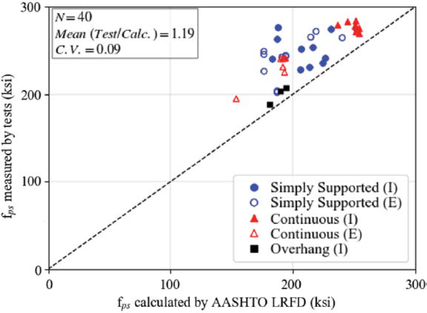
Figure 2.3 shows a comparison of the weighted average of fps of bonded and unbonded strands as calculated according to the LRFD BDS (AASHTO 2020) and as measured by 40 selected tests described in Table 2.5. Segmental specimens that failed at the joints [two specimens from Brenkus et al. (2017a) and a specimen for which unbonded strand stress was not reported from Yoo and Ha (2010)] are excluded from Figure 2.3. While fps was reported for all unbonded strands in the tests, it was not reported for all bonded strands. When fps was not reported for the bonded strands, it was calculated using Equation 2.1 to determine the average fps as measured by tests shown in Figure 2.3. The average fps according to the LRFD BDS approach was obtained from the simplified method that assumes the fps of unbonded strands is equal to the effective prestress, fpe. For bonded strands, fps was calculated using Equation 2.1. The number of tests available in the literature for beams with bonded and unbonded strands is small. Nevertheless, the mean of the ratio of fps from tests to calculated values and the corresponding CV are 1.19 and 0.09, respectively. The type of unbonded strands (external [E] or internal [I]) are also indicated in the legend in Figure 2.3. As shown, the predictions for fps are conservative (above the 45-degree line).
2.3 Shear Strength
2.3.1 Introduction
While there can be significant advantages to unbonded systems, a major question arises regarding the shear strength of these systems. There are two primary areas of concern:
- With an unbonded system, the axial stiffness of the longitudinal reinforcement is reduced. Research has shown that the reinforcement ratio, which is reflective of the axial stiffness of the reinforcement, is a primary variable for the shear strength of the concrete (Tureyen and Frosch 2003; Wolf and Frosch 2007). Furthermore, in evaluating the shear strength of both prestressed members and partially prestressed members, this theory was further supported where members resulted in identical shear strengths if the axial stiffness of the reinforcement was identical (Saqan and Frosch 2009). Therefore, unbonded post-tensioned systems relative to bonded systems are expected to result in a lower shear strength provided by the concrete.
- With an unbonded system, the ducts create voids. Even with flexible fillers, it is not expected that the filler material will provide shear or compressive resistance. For ducts provided in the webs, a reduction of shear strength is expected due to the presence, size, and location of the duct. The duct introduces a discontinuity for diagonal compressive stresses, which develop when stirrups are being engaged. It is expected that a significant reduction in shear strength can result. Overall, the maximum capacity of the web to resist shear will be reduced depending on the size and location of the duct.
2.3.2 Members with Bonded Strands in Shear
Researchers at The University of Texas at Austin (UT Austin) conducted a large-scale experimental program investigating the effect of grouted post-tensioning ducts in the thin webs of bulb tee girders on the shear strength and behavior of the members (Moore et al. 2015, 2017). The test program consisted of 11 shear tests on bulb tee girder specimens, 10 of which were conducted on specimens containing a post-tensioning duct in the thin webs of the girders. The specimens had a depth of 70 in. Each specimen with a post-tensioning duct experienced a shear failure characterized by the crushing of concrete in the vicinity of the duct. The reduction in shear strength due to the presence of the post-tensioning ducts was documented (Moore et al. 2015, 2017).
Several important conclusions resulted from the UT Austin study, including the observation that no notable difference in shear strength existed between specimens with grouted steel ducts and those with grouted plastic ducts. Contrary to this finding, however, Eurocode 2 and fib Model Code 2010 include shear strength reductions that are more severe for members with plastic ducts than members with steel ducts. These code provisions are consistent with the results of compression tests on small-scale panels containing post-tensioning ducts. The UT Austin study, however, demonstrated that such panel tests are not representative of the shear mechanism of bridge girders (Moore et al. 2015, 2017).
The research results of the UT Austin study on post-tensioned members provided evidence that premature crushing of the web concrete due to the presence of a duct limited the strength contribution of the transverse reinforcement. Considering the truss mechanism of shear transfer through the girders, the researchers stated that premature crushing due to compression in the web limits the shear stresses than can be transferred to the transverse shear reinforcement. The study also indicated that failure of each post-tensioned girder specimen occurred at a shear force less than the 0.25f′cbvdv + Vp limit for Vn and stated “even though the shear forces were below this limit, the failure of each post-tensioned test specimen was characterized by localized crushing in the vicinity of the duct” (Moore et al. 2017). It should be noted that, at the time of this study, bv was defined in Article 5.8.2.9 of the 7th edition of the LRFD BDS (AASHTO 2014) as the web width minus half the diameter of ungrouted ducts or a quarter of the diameter of grouted ducts. Since that time, the LRFD BDS has modified the definition of bv regarding the reductions made for both grouted and ungrouted ducts (AASHTO 2020).
Figure 2.4(a) shows that a significant increase in shear reinforcement, represented by ρv fy, resulted in little increase in the normalized shear capacity. The ratio of the experimental shear capacity Vtest and the calculated shear strength Vn based on LRFD BDS is plotted in Figure 2.4(b) against ρv fy, where ρv is the transverse reinforcement ratio and fy is the transverse reinforcement yield strength. As the value of ρv fy increased, the ratio Vtest/Vn experienced a steady decrease. In other words, as more shear reinforcement was added to the specimens, the nominal shear capacity increased due to the increase in the calculated value of Vs (shear resistance provided by transverse reinforcement), but the experimental capacity, Vtest, did not increase at the same rate. Moore et al. (2015, 2017) indicated that the effect of the duct on the Vs term (i.e., the decrease in efficiency of the shear reinforcement) was not accurately captured by the 7th edition LRFD BDS shear design provisions (AASHTO 2014).
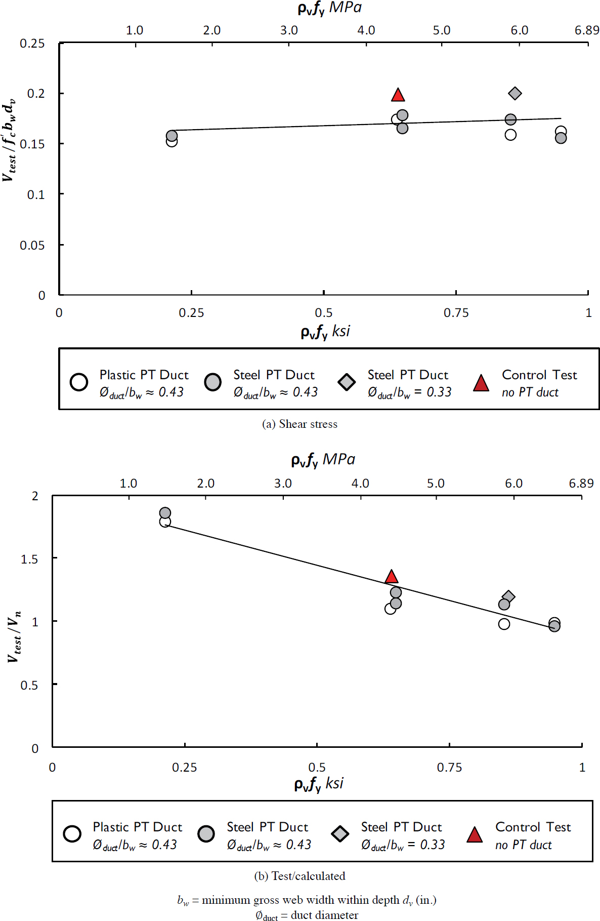
The UT Austin study included specimens with duct diameter to web width ratios of 0.33, 0.43, and 0.44. The variation in duct diameter to web width ratio did not cause a difference in the shear failure mechanism of the specimens. The duct diameter to web width ratio did, however, influence the shear stresses in the specimen at failure and caused the shear stress at failure to decrease as the duct diameter to web width ratio increased. A duct diameter to web width ratio of 0.33 resulted in a shear stress at failure of 0.20f′c, and the specimens with duct diameter to web width ratios of 0.43 and 0.44 had a shear stress at failure of 0.16f′c to 0.18f′c (Moore et al. 2015).
The researchers at UT Austin made recommendations for revisions to the shear design procedure in the 7th edition of the LRFD BDS (AASHTO 2014). The recommendations included changes to equations for the nominal shear resistance of the concrete (Vc), the shear resistance provided by transverse reinforcement (Vs), and the upper limit for nominal shear resistance (Vn). The 2017 LRFD BDS procedure and the modifications proposed by Moore et al. (2015) are outlined in Table 2.6. Proposed modifications are bolded and set in red.
While the UT Austin study was a major investigation that resulted in changes that are included in the 9th edition of the LRFD BDS (AASHTO 2020), a variety of other studies have been conducted on the shear behavior of girders with bonded tendons located in the web, and these studies are summarized in Table 2.7.
Ruiz and Muttoni (2008) studied the shear behavior of five bridge girders with a height of 52 in. from a continuous span bridge in Switzerland. Similar to the specimens in the UT Austin study, the failure of each specimen tested by Ruiz and Muttoni (2008) was characterized by crushing of web concrete in the vicinity of the ducts coupled with spalling of the concrete cover along the profile of the tendons. A study of small-scale I-beams with grouted post-tensioning ducts further demonstrated that the shear failure of a beam with a post-tensioning duct in the web was characterized by crushing of concrete in the vicinity of the duct (Chitnuyanondh 1976). The small-scale specimens also had a lower shear capacity compared to the shear capacity of small-scale specimens without post-tensioning ducts in the web of the member (Chitnuyanondh 1976). An additional study conducted at UT Austin (Han et al. 2022) compared the behavior of large-scale post-tensioned girders with bonded or unbonded tendons in the web with varying tendon layouts. The failure mechanism of the grouted specimens tested by Han et al. (2022) was also characterized by the crushing of web concrete in the vicinity of the duct.
Table 2.6. 7th edition LRFD BDS equations for Vc and Vs and proposed modifications.
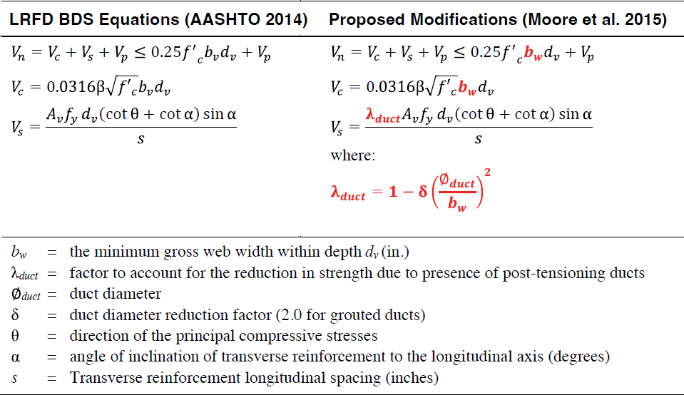
Table 2.7. Summary of shear tests on members with bonded tendons.
| Reference | Support Type | Shear Span/Depth Ratio (a/h) | Beam Type | No. of Ducts in Web | ØDuct / Web Width | P/S Profile | Area of P/S Aps (in.2) | Area of Mild Steel As (in.2) | As /Aps | Concrete Strength f′c (ksi) | No. of Specimens |
|---|---|---|---|---|---|---|---|---|---|---|---|
| Chitnuyanondh (1976) | Simply Supported | 2 | I | 1 | 0.5 | Draped | 0.46 | 1.2 | 2.61 | 3.5-6.4 | 5 |
| Rezai-Jorabi and Regan (1986) | Simply Supported | 3.7, 3.1 | I,T | 0-3 | 0.43 | Draped Straight | 1.18-2.14* | 0.35, 1.95 | 0.35-2.92 | 4.5-6.5 | 13 |
| Ruiz and Muttoni (2008) | Simply Supported | 1.8-3.3 | Bulb-T | 2 | 0.48 | Draped | 3.85 | 0.40 | 0.10 | 6.8-8.7 | 6 |
| Lee et al. (2010) | Simply Supported | 2.08 | I | 1 | 2 | Draped | 0.87-1.75 | 10.2 | 1.72-5.83 | 6.6-12.3 | 7 |
| Rupf et al. (2013) | Simply Supported w/overhang | 6.2 | I | 1 | 0.33 | Draped | 0.98, 3.37 | 2.86-6.63 | 2.69-7.13 | 4.1-5.4 | 8 |
| Moore et al. (2015) | Simply Supported | 2.4 | Bulb-T | 1 | 0.46–0.51† | Straight | 12.70, 13.92 | 0 | 0 | 10.6-13.9 | 10 |
| Williams et al. (2015) | Simply Supported | 2.6 | Bulb-T | 3 | 0.51† | Draped | 7.81 | 0 | 0 | 9.5, 10.1 | 2 |
| Han et al. (2022) | Simply Supported | 2.4 | Bulb-T | 1 | 0.5† | Draped Straight | 16.3, 20.4 | 0 | 0 | 13.7-14.4 | 3 |
*Nominal area of prestressed reinforcement
†Outside diameter of duct
Lee et al. (2010) investigated the shear behavior of girders with a shear span-to-depth ratio of 2.5 and focused on shear deformations and ultimate shear capacity. The researchers found that stirrups in post-tensioned specimens limited diagonal crack width, the shear reinforcement ratio was the dominant factor in the arch action of a girder with a small shear span-to-depth ratio, and the prestressing force only increased the cracking load of the member. Rupf et al. (2013) concluded that the shear reinforcement ratio and the prestressing force impacts the failure mechanism of a post-tensioned girder. Flanged specimens with a shear reinforcement ratio of 0.086% or lower and a longitudinal stress due to prestressing force of 2.45 MPa (0.355 ksi) or lower experienced failures with cracking throughout the depth of the web, fracture of the stirrups, and flange delamination. Flanged specimens with higher shear reinforcement ratios and prestressing forces failed with concrete crushing occurring locally along the post-tensioning duct (Rupf et al. 2013).
2.3.3 Members with Unbonded Internal Strands in Shear
A small number of studies have been conducted to investigate the shear behavior of girders with unbonded tendons located in the web, and these studies are summarized in Table 2.8.
A research program at Queen’s University in Kingston, Ontario (Chitnuyanondh 1976), included tests on a total of 13 small-scale I-beams, three of which had an ungrouted duct within the web of the member. The specimens had a height of 16 in. and a web width of 1.75 in. The transverse reinforcement was varied between the three specimens and spaced at 3 in., 4 in., and 5 in., resulting in transverse reinforcement ratios of approximately 1.96%, 1.31%, and 1.00%, respectively. The failure mechanisms of the ungrouted beams, as well as the grouted beams, were characterized by the crushing of concrete in the vicinity of the duct. The specimen with stirrups spaced at 5 in. exhibited cracks in the web parallel to the duct in the shear span before load was applied. These cracks were barely noticeable and appeared to be discontinuous. As load was applied, the cracks began to disappear and were unnoticeable at an approximate shear of 0.18Vtest, where Vtest is the shear at failure. The cracks parallel to the ducts were eliminated by decreasing the stirrup spacing (Chitnuyanondh 1976). The program also concluded that the shear strengths of specimens with an ungrouted duct in the web resulted in a decreased shear capacity when compared to the shear capacity of similar specimens with a grouted duct in the web. While the shear capacity decreased, the overall stiffness of the member was not affected by the presence of an ungrouted or grouted duct in the web when compared to a beam without a duct in the web (Chitnuyanondh 1976).
More recently, research programs at the University of Florida (Skelton and Hamilton 2021) and UT Austin (Han et al. 2022) conducted large-scale experimental investigations of members with unbonded internal strands located in the webs. The Florida study focused on the number of ducts contained in a web, the amount of transverse reinforcement, the presence of a top flange, web width, and the duct diameter to web width ratio. Similar to specimens with bonded tendons, it was shown that an increase in duct diameter to web width ratio reduces the strength of the girder, and specimens with unbonded web tendons experience a failure mechanism characterized by crushing at the location of a duct. Skelton and Hamilton (2021) also tested specimens in positive and negative bending. Both loading cases experienced similar failure mechanisms.
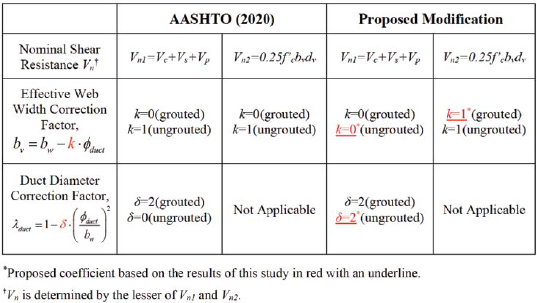
The study by Han et al. (2022) focused specifically on the behavior of specimens with unbonded web tendons and compared the behavior to identical specimens with bonded web tendons. Three specimens with unbonded web tendons, each with a different tendon profile, and three identical specimens with bonded web tendons were constructed. The study showed that the unbonded and bonded specimens had similar failure mechanisms, characterized by crushing at the level of the duct, and the failure mechanisms were not influenced by the tendon profile. Based on the results of this testing program, modifications to the 2020 LRFD BDS were recommended to define the effective web width correction factor, k, and duct diameter correction factor, δ, for unbonded tendons.
Table 2.8. Summary of shear tests on members with unbonded tendons.
| Reference | Support Type | Shear Span/Depth Ratio (a/h) | Beam Type | No. of Ducts in Web | ØDuct / Web Width | P/S Profile | Area of P/S Aps (in.2) | Area of Mild Steel As (in.2) | As/Aps | Concrete Strength f′c (ksi) | No. of Specimens |
|---|---|---|---|---|---|---|---|---|---|---|---|
| Chitnuyanondh (1976) | Simply Supported | 2 | I | 1 | 0.5 | Draped | 0.46 | 1.2 | 2.61 | 4.3–5.0 | 3 |
| Skelton and Hamilton (2021) | Simply Supported* | 2.2, 3 | Bulb-T | 0–2 | 0.26–0.64 | Draped | 3.83, 5.21 | 0 | 0 | 9.3–13.7 | 20 |
| Han et al. (2022) | Simply Supported | 2.4 | Bulb-T | 1 | 0.5† | Draped Straight | 16.3, 20.4 | 0 | 0 | 13.4–13.7 | 3 |
*Included positive and negative bending
†Outside diameter of duct
Modification to the effective web width correction factor, k, for bonded tendons was also proposed to provide the same k factor for both bonded and unbonded tendons consistent with the finding that there is not a significant change in strength due to the presence of grouted tendons. The current provision and the proposed modifications are summarized in Table 2.9.
Parsons Brinckerhoff Inc. conducted a study for the Florida Department of Transportation to evaluate the applicability of the modified compression field theory (MCFT) shear design procedures in the 7th edition of the LRFD BDS, released in 2014 (AASHTO 2014), for unbonded post-tensioned tendons to assist with the implementation of flexible fillers for post-tensioned bridges in Florida (Florida DOT 2015). The study reviewed the applicability of Articles 5.8.3 and 5.8.6 to unbonded tendons in segmental and non-segmental post-tensioned bridges. The study assumed that, in an unbonded member, the precompressed tensile zone remains uncracked and concrete in this region can resist the longitudinal force from the inclined compression struts. It was further assumed that, in areas where flexural cracking can occur, behavior is based on a shallow arch. Two design examples (a span-by-span precast segmental box girder and a three-span spliced girder) were developed to evaluate shear resistance according to the general procedure using MCFT (Article 5.8.3). The 45° modified truss analogy method (Article 5.8.6) was also considered for the segmental box girder. For the segmental example, it was shown that the shear strength with unbonded tendons is “functionally equivalent” to the bonded case in areas without cracking which is where high shears are expected. Significant reductions occurred in locations with cracking. The spliced girder bridge example assumed bonded prestressing in the precast girders along with unbonded tendons that provided continuity. Because of this configuration, the unbonded tendons were simply treated as bonded throughout the entire member with the exception of the splice location. Based on these two examples, it was concluded that MCFT is “still applicable to unbonded tendons provided that the proper limitations of the prestressing are observed.” It was also noted that shear and torsion design must consider the reduced concrete section due to inclusion of ungrouted ducts. The study, however, indicated concerns regarding the use of MCFT for the design of long-span segmental bridges as this method may result in thinner webs due to the higher limit on Vn allowed by MCFT relative to the modified truss analogy method. Therefore, it was recommended that a modified limit on Vn be provided for the design of segmental bridges using MCFT. It was also recommended for segmental bridges that the design check of the longitudinal reinforcement for additional tensile force due to shear, which is required using MCFT, also
Table 2.9. Han et al. (2022) proposed modifications.
be required for the modified truss analogy. Finally, due to the limited research available on shear and torsion for unbonded tendons, additional research was recommended (Florida DOT 2015).
2.4 Torsional Strength
No known research examining the applicability of current torsional strength expressions on members with unbonded post-tensioned tendons has been published. A few studies, however, have examined aspects of the torsional behavior of post-tensioned concrete elements. Mitchell and Collins (1978) experimentally evaluated the influence of torsion on grouted post-tensioned tendons in corrugated metal ducts. Six specimens were tested. The specimens had varying longitudinal reinforcement, but the transverse reinforcement remained the same for each specimen. Four specimens were solid rectangular members, while the remaining two specimens were hollow with 3.5-in. web thicknesses. The ducts were reported to have diameters of 25 mm (1 in.), resulting in a duct diameter to web width ratio of 0.29. With this ratio, no influence of the presence of the duct itself was reported. The authors noted that no difference exists in the torsional response between hollow beams and solid beams with the same post-tensioning characteristics. Furthermore, the twist-torsion curves developed from the test data indicated that, as the amount of post-tensioning force increased, the torque at cracking, torque at yield of the transverse reinforcement, and the ultimate capacity increased, but the ductility and failure twist angle decreased. Additionally, Mitchell and Collins (1978) hypothesized from the test results that inclined tendons provide a higher torsional resistance relative to straight tendons as a function of the tangential forces of the inclined tendon.
Al-Gorafi et al. (2009, 2010, 2011a, 2011b) conducted a series of experiments and analyses to investigate the effect of torsion on externally prestressed segmental box girders. In these studies, all tendons were external, and significant attention was placed on joint details and behavior. In the 2011 study (Al-Gorafi et al. 2011a), an analytical investigation was conducted using finite element models to compare the torsional behavior of monolithic and segmental post-tensioned elements with external tendons. The results revealed differences between monolithic and segmental members; however, the work does not provide insight into the applicability of current design procedures for post-tensioned concrete elements.
2.5 AASHTO Specification Limitations
The LRFD BDS (AASHTO 2020) and LRFD Bridge Construction Specifications (BCS) (AASHTO 2017a) were reviewed to identify provisions that may require additional information, clarification, or revision to fully address bonded/unbonded and internal/external post-tensioned tendons and various combinations of tendon types. Relevant material on this topic was also reviewed (Montgomery 2019). The following provisions were identified that may require changes:
- Definitions for internal tendon, external tendon, bonded tendon, unbonded tendon, grouted tendon, ungrouted tendon, and flexible filler (AASHTO 2020, Article 5.2).
- Clear definitions of tendon types and filler material are needed to ensure the design community uses consistent language and understands the assumed behavior of various post-tensioning systems. For example, grouted internal tendons are considered to be bonded and exhibit strain compatibility. Grouted external tendons, however, are considered to be unbonded and do not exhibit strain compatibility.
- Shear and torsional strength reduction due to the presence of grouted and ungrouted ducts (AASHTO 2020, Article 5.7.2.1, Article C5.7.2.1, Article 5.7.2.8, Article C5.7.2.8, Article 5.7.3.3, Article 5.7.3.4.2, Article C5.7.3.4.2, Article 5.7.3.6.2).
- Previous research (Moore et al. 2015, 2017) has indicated that internal grouted post-tensioning ducts located in the webs of bridge girders result in a reduction in shear strength.
- Design specifications were recently updated to address the shear strength of grouted ducts. Due to the lack of research data, the effect of internal ungrouted ducts on the shear strength of members is not thoroughly understood. The same lack of understanding also applies to torsional strength. The results of the current research will lead to proposals for updated provisions to account for the reduction in shear and torsional strengths due to the presence of both grouted and ungrouted ducts.
- Value of εs to use within the general procedure of shear design for members with unbonded tendons (AASHTO 2020, Article 5.7.3.4.2, Article C5.7.3.4.2).
- The shear design procedure in Article 5.7.3.4.2 of the current AASHTO LRFD BDS (AASHTO 2020) is based on the modified compression field theory. The calculated shear strength is dependent on the net longitudinal strain in the concrete at the centroid of the tension reinforcement, εs. This strain value is used to estimate the direction of the principal compressive stresses, θ. The value of εs is based on the stress in the prestressed reinforcement. More specifically, Equation 5.7.3.4.2-4 of LRFD BDS (AASHTO 2020) for the calculation of εs is dependent on the value of fpo, which is equal to the modulus of elasticity of the prestressing steel multiplied by the locked-in strain differential between strands and the surrounding concrete. With the inclusion of unbonded strands, the current method for calculating εs must be revised. Incorrect use of the current procedure for a system with unbonded tendons may result in an underestimation of the angle θ, leading to unconservative nominal shear strength values. Additionally, because the estimate of torsional resistance (Article 5.7.3.6.2) depends on the value of θ, incorrect estimations of εs may also lead to unconservative nominal torsional strength values.
- Value of the average stress in prestressing steel at nominal flexural resistance, fps, for members with both bonded and unbonded tendons and the appropriateness of applying simplified flexural analysis to such members (AASHTO 2020, Article 5.6.3.1.3).
- To calculate the nominal flexural resistance of members with a combination of bonded and unbonded tendons, the current specifications provide the designer with two options: a detailed analysis or a simplified analysis. The detailed analysis requires that strain compatibility be used to determine the stress in the bonded strands at the nominal moment condition, while stress in the unbonded tendons must consider global displacement compatibility. Implementing this detailed analysis can be quite complex, and methods used to predict deflections at the strength limit state in order to estimate the stress in unbonded tendons may be unreliable. Alternatively, the simplified analysis limits the stress in unbonded tendons to a maximum value of fpe. While this assumption is conservative, any increase in flexural capacity caused by the increase in strain at the nominal moment condition is not considered. Therefore, a simple, refined method is needed to accurately estimate fps for members with both bonded and unbonded tendons.
- Reduction of web width for principal tensile stress checks when grouted or ungrouted internal tendons are present (AASHTO 2020, Article 5.9.2.3.3, Article 5.7.2.1, Article C5.7.2.1).
- Article 5.9.2.3.3 of the current LRFD BDS (AASHTO 2020) limits principal tensile stresses in the webs of post-tensioned structures at the service limit state. The purpose of the provision is to limit web cracking in post-tensioned members. The calculations for estimating stresses must account for the presence of internal tendons located at the depths where principal tension stresses are being checked. The provisions of Article 5.7.2.1 are referenced in regard to appropriately modifying the web width for the effects of internal tendons. The final paragraph of Article C5.7.2.1 states that the current recommendation is to reduce the web width by one-half the diameter of grouted ducts and the full diameter of ungrouted ducts. This recommendation may require adjustment.
- Ungrouted ducts during construction (AASHTO 2020, Article 5.12.3.4.4).
- Within the provisions for spliced precast girders, Article 5.12.3.4.4 of the current LRFD BDS (2020) states that “The contract documents shall require that all post-tensioning tendons
- shall be fully grouted after stressing.” This requirement is based on the assumption that all tendons will be internal and bonded. Language will need to be updated to include the potential for external and/or unbonded tendons.
- Other provisions that require consideration of reduced web widths due to the presence of post-tensioning ducts (AASHTO 2020, Article 5.7.2.1, Article C5.7.2.1, Article 5.7.2.5, Article 5.7.2.8, Article C5.7.2.8).
- Other provisions within the current LRFD BDS (AASHTO 2020) require consideration of the effects of the discontinuity introduced by the presence of post-tensioning ducts. These provisions include calculations for the torsional cracking moment for hollow shapes, minimum transverse reinforcement, and shear stress over the depth of a section.
- Requirement for longitudinal reinforcement in members with unbonded tendons or a combination of bonded and unbonded tendons (AASHTO 2020, Article 5.7.3.5, Article 5.7.3.6.3).
- Articles 5.7.3.5 and 5.7.3.6.3 of the current LRFD BDS (AASHTO 2020) provide requirements for the tensile capacity that must be provided by longitudinal reinforcement in a member. Although the requirements are based on equilibrium, specific terms in the expressions included in the specifications may be affected by the findings of the current research. More specifically, the values of fps and the direction of the principal compressive stresses, θ, must be calculated with consideration of the stresses in unbonded tendons or combinations of bonded and unbonded tendons.
- Design of segmental joints for flexural, shear, and torsion when a combination of bonded and unbonded tendons are used (AASHTO 2020, Article 5.12.5.2.3, Article C5.12.5.2.3).
- The current specifications require consideration of the potential opening of the joints of segmental bridges made continuous by unbonded tendons. Because the tendons are unbonded, unreinforced joints may open as the strength limit state is approached, affecting the distribution of forces at the joint. In this context, the specifications do not address segmental bridges with a combination of bonded and unbonded tendons across a joint.
- Details of anchorages, deviators, and duct material to facilitate replaceability (not currently addressed in specifications).
- One of the main drivers of using unbonded tendons is to facilitate the replaceability of prestressing strands. To account for this, consideration should be given to future replacement during the design phase. Access at anchorages for equipment needed for removing and reinstalling tendons will require significant design and detailing on the part of the engineer of record. Although this item is beyond the scope of the current research, it is an important consideration for design and is recommended for future research.
- Temporary design condition for short-term tendon elongation caused by installation of a high-temperature flexible filler in ungrouted ducts (not currently addressed in specifications).
- The significant change in temperature within tendons caused by the installation of heated flexible fillers during construction may lead to temporary conditions that should be addressed during the design phase. Although this item is beyond the scope of the current research, it is an important consideration for design and is recommended for future research.
- Use of smooth and corrugated ducts (AASHTO 2020, Article 10.8.3).
- The current construction specifications only address corrugated plastic ducts that are completely embedded in concrete. The use of smooth ducts is appropriate for unbonded post-tensioning applications; therefore, this provision will require future modification to address smooth plastic ducts that are completely embedded in concrete.
For the current research project, consideration will be given to the revision of design specifications corresponding to the use of unbonded tendons and the combination of internal/external and bonded/unbonded tendons as they relate to the provisions listed above. Furthermore, new guidelines and/or specifications will be developed as needed in accordance with the findings of the analytical and experimental investigations.


