Strategies to Address Utility Issues During Highway Construction (2024)
Chapter: 8 UTILITY INSPECTION PROCEDURES
CHAPTER 8. UTILITY INSPECTION PROCEDURES
This chapter summarizes the work the research team completed to develop procedures for conducting utility inspections. The procedures include data collection equipment, software, and protocols. As part of this task, the research team conducted field tests to assess the positional accuracy of low-cost data collection equipment. Readers should be aware that the focus was inspection activities that involve verification of locations, dimensions, areas, and volumes, not other related utility inspection activities such as verification of materials or the completion of inspection diaries.
DATA COLLECTION EQUIPMENT
Unmanned Aircraft Systems
Most UAS applications used for inspections involve the use of small rotary platforms. The National Defense Authorization Act (NDAA) specifies the annual budget and expenditure levels approved for the U.S. Department of Defense (DOD). Section 848 of the Fiscal Year 2020 NDAA included a provision prohibiting the procurement of Chinese-made UASs (111). Since then, federal agencies have taken additional actions highlighting the threat of these UASs to the security of the United States (112, 113, 114). States are also increasingly banning the use of non-approved UASs on state-owned networks and state contracts, including highway construction projects (115).
The Defense Innovation Unit within the DOD has an initiative called Blue UAS that vets commercial UAS technology for government applications (116). A certification program called Blue sUAS 1.0 focused on low-cost, rucksack portable, vertical takeoff and landing UASs. Blue sUAS 2.0 expanded the certification options to a broader range of sizes, capabilities, price ranges, and flight modalities.
Examples of NDAA-compliant UASs that are suitable for conducting utility inspections include the Parrot Anafi USA and Skydio X2D Color. The Anafi USA is a small quadcopter UAS with a 21-megapixel (MP) complementary metal-oxide semiconductor (CMOS) image sensor. The UAS weighs 0.5 kg (1.1 lb) and measures 28×37×8.2 cm. The UAS has a built-in camera and does not support exchangeable payloads. The camera pitch ranges from –90° to +90°, enabling the collection of imagery looking up. The UAS does not have substantial obstacle avoidance capabilities. The maximum flight time is about 32 minutes.
The Skydio X2D Color is a quadcopter UAS with a 12-MP CMOS image sensor. The UAS weighs 1.3 kg (2.9 lb) and measures 30×15×10 cm. The Skydio X2D has a built-in camera and does not support exchangeable payloads. A separate configuration has both color and thermal sensors. The camera pitch ranges from –90–90°, enabling the collection of imagery looking up. The UAS has omnidirectional obstacle avoidance capabilities. The UAS has white and infrared strobing lights, which enables the UAS to be used at night. The maximum flight time is about 35 minutes.
Mobile Devices
Smartphones and Tablets
Until a few years ago, mobile devices in the United States could only capture signals from the Global Positioning System (GPS). L1 is the oldest GPS signal. For the civilian market, it broadcasts Coarse Acquisition (C/A) Code using a 1575.42 MHz frequency, which enables a horizontal positional accuracy of about 5 m (16 ft). L2 was implemented after L1. It uses the 1227.60 MHz frequency and is normally used by multi-frequency receivers.
Recent smartphones have the capability to receive data from multiple GNSS constellations, such as GPS (United States), GLONASS (Russia), Galileo (European Union), BeiDou (China), Quasi-Zenith Satellite System (QZSS) (Japan), and Navigation with Indian Constellation (NavIC) (India). With respect to GPS signals, mobile devices are increasingly providing support for L1 and L5 signals. L5 operates at 1176 MHz, is less prone to multipath errors, and can be used to refine positional accuracy (117). It is not clear whether recent smartphones provide support for L2 signals. The GNSS industry reports that newer chips can achieve meter or submeter horizontal positional accuracy, with some mass market GNSS vendors reporting a 30-cm (1-ft) horizontal positional accuracy (118, 119). Experiments have also taken place by adding RTK corrections to smartphone-GNSS data, resulting in horizontal positional accuracies of about 2 cm (0.8 in) (120).
A wide range of mobile devices are suitable for conducting utility inspections. The research team examined two smartphones (Samsung Galaxy S22 and Apple iPhone 14 Pro Max) and two tablets (Samsung Tab Active3 and Apple iPad Pro 11).
The Samsung Galaxy S22 is a 6.1-inch smartphone that runs on Android 12. It has three rear cameras, including a 50-MP main camera, 12-MP ultra-wide camera, and a 10-MP telephoto camera. Video resolutions are 8K (33 MP), 4K (8 MP), 2 MP, and 1 MP. The built-in GNSS antenna provides dual frequency support (L1 and L5) but the model the research team used only received L1 frequency data. The phone includes support for mock locations (i.e., a feature that enables the phone to receive and process GNSS locations from external antennas). The phone also has a feature to force full GNSS measurements (i.e., a feature that enables tracking of all GNSS constellations and frequencies with no duty cycling). When duty cycling is on, the phone turns the GNSS receiver power on and off repeatedly to reduce power consumption, effectively causing the GNSS receiver to restart when power is restored. When duty cycling is off, the GNSS antenna is always powered.
The Samsung Tab Active3 is an 8-inch rugged tablet that runs on Android 12. It complies with U.S. military standard MIL-STD-810H and has an ingress protection rating of 68 with respect to dust, dirt, sand, water, and mechanical shock. The tablet has a rear camera with a 4160×3120-pixel (13 MP) image resolution. Video resolution is 1920×1080 pixels (2.1 MP). The built-in GNSS antenna provides single frequency support (L1). The Samsung Active Tab3 includes support for mock locations and full GNSS measurements.
The Apple iPhone 14 Pro Max is a 6.7-inch smartphone that runs on iPhone Operating System (iOS) 16. It has three rear cameras, including a 48-MP main camera, a 12-MP ultra-wide
camera, and a 12-MP telephoto camera. Video resolutions are 4K (8 MP), 2 MP, and 1MP. The built-in GNSS antenna provides dual frequency support (L1 and L5). As opposed to Android, iOS does not use a setting like the mock location feature. Instead, access to external antennas is handled at the app level directly, making it unnecessary for users to enable external GNSS antennas separately. The iPhone 14 Pro Max has a LiDAR scanner. When combined with the camera sensors, the phone can generate colorized RGB point clouds. Apple does not publish the technical specifications of the LiDAR scanner, but according to third party articles, a vertical cavity surface emitting laser (VCSEL) emits an array containing 8×8 points diffracted into 3×3 grids making a total of 576 points (121, 122). The maximum range is 5 m (16 ft). The potential point density is 7,225 points/m2 at 25 cm and 150 points/m2 at 2.5 m. These specifications apply to the iPhone 12 Pro, and it is unclear whether the iPhone 14 Pro LiDAR has similar specifications. The 576 points are not illuminated at the same time. The system illuminates 144 points and then cycles through the remaining points in 144-point increments.
The Apple iPad Pro 11 is an 11-inch tablet that runs on iOS 16. The tablet has two rear cameras, including a 12-MP wide camera and a 10-MP ultra-wide camera. Video resolutions are 4K (8 MP), 2 MP, and 1MP. The built-in GNSS antenna provides single frequency support (L1). The iPad Pro 11 has a LiDAR scanner. Apple does not publish the technical specifications of the LiDAR scanner. However, from reports in the literature, the LiDAR specifications are similar to those on the iPhone.
External GNSS Antennas
Survey-grade GNSS equipment is commonplace at construction sites. This type of equipment and companion services cost anywhere from $15,000–$30,000 upfront in addition to differential correction subscription fees. Of interest here are devices and companion services that offer cm-level positional accuracy at lower costs than traditional GNSS equipment. A typical business model is one in which the cost of the GNSS antenna is low (say $500–$5,000). The receiver provides a positional accuracy between 60 cm (2 ft) and 1.5 m (5 ft) in autonomous mode, but when connected to an RTK correction subscription service, the positional accuracy improves up to 1–3 cm horizontally. RTK subscription rates range from $4,000 per year to $400 per month or $100 per day. Depending on the brand and model, GNSS receivers can connect to public RTK networks for free, but in other cases, users must pay an unlocking or access fee to the GNSS vendor, after which it is possible to connect to the public RTK network.
The research team examined the following external GNSS antennas: Bad Elf Flex, Leica Zeno FLX100 Plus, Trimble DA2, and viDoc RTK Rover. The research team also examined whether these GNSS antennas could connect to a number of RTK networks. The research team also had access to the TxDOT real-time network (RTN), which made it possible to assess whether the GNSS antennas could connect to this network.
For the Bad Elf Flex GNSS receiver, differential correction options include Satellite-Based Augmentation System (SBAS), RTK, and L-band Atlas. The Bad Elf Flex receiver is priced at $3,000. This price includes free access to SBAS corrections. Bad Elf offers a subscription to Point One Navigation RTK corrections. The commercial cost of this subscription is $1,000/year (or $100/month). In addition to Point One Navigation, the research team was able to connect the Bad Elf Flex receiver to HxGN SmartNet and the TxDOT RTN, but not Trimble Catalyst. To
access cm-level positional accuracy from any RTK network (including Point One Navigation), it is necessary to pay an unlocking fee of $3,000 (one time) or on a token basis, where each token is $25 and lasts for 24 hours upon activation.
For the Leica Zeno FLX100 Plus GNSS receiver, differential correction options include SBAS and RTK. The Leica Zeno FLX100 Plus receiver is priced at $5,500. This price includes free access to SBAS corrections. Users can also access RTK networks without having to pay an unlocking fee. Leica offers a subscription to the cm-level HxGN SmartNet RTK correction service. The commercial cost of this subscription is $4,600/year (or $875/month) nationwide. Different prices apply for regional or state-level access. In addition to HxGN SmartNet, the research team was able to connect the Leica Zeno FLX100 Plus receiver to the TxDOT RTN.
For the Trimble DA2 GNSS receiver, differential correction options include SBAS, RTK, and Trimble RTX. The Trimble DA2 receiver is priced at $395. Trimble offers several Catalyst RTK levels, ranging from Catalyst 60 (60-cm accuracy) to Catalyst 1 (1-cm accuracy). Catalyst subscribers also have access to other Trimble correction services, including Virtual Reference Station Now and RTX. Catalyst 1 costs $3,900 per year, $390 per month, or $115 for 10 hours on demand. In addition to Catalyst 1, the research team was able to connect the Trimble DA2 receiver to the TxDOT RTN. Users can access RTK networks other than Catalyst, but it is first necessary to have a Catalyst subscription.
viDoc RTK Rover is an external GNSS receiver that is mounted on certain smartphones or tablets. The receiver needs an RTK connection to work. Without this connection, the rover is still connected to the mobile device via Bluetooth but does not output coordinates. The viDoc RTK Rover is priced at $5,990. Connecting the receiver to an RTK network does not require paying an unlocking fee (although access to the RTK might involve a fee depending on the network). The research team confirmed the viDoc RTK Rover could connect to HxGN SmartNet and the TxDOT RTN.
DATA COLLECTION SOFTWARE
Of interest here are apps that enable users to complete activities such as, but not limited to the following:
- Upload a data dictionary to the device and collect data using preestablished feature classes and drop-down lists.
- Take pictures and videos and associate these data elements with specific features.
- Compare the location of design-level features vs. what was built.
- Gather and document unstructured point, line, and polygon data.
- Collect picture sets needed for SfM photogrammetry and the production of 3D models.
- Collect LiDAR data needed to produce 3D models.
- Add comments.
Examples of apps include Trimble Penmap, Leica Zeno Mobile, ArcGIS Field Maps, ProStart PointMan, PIX4Dcatch, and Bentley iTwin Capture Mobile. Trimble Penmap is a mobile app that supports typical survey tasks and workflows, including control points, topo, and stakeouts. The stakeout function enables users to stake out points, including comparing design locations
versus actual locations on the ground. Penmap synchronizes with Trimble Connect to upload and transfer data between the mobile device and the cloud. Trimble Connect is a cloud-based platform for setting up, managing, and deploying data collection projects. Penmap runs on Android devices.
Leica Zeno Mobile is a mobile app that enables the collection of feature data in the field. Depending on the version, the app supports typical surveying functions, including stakeouts. It enables users to load project information that was previously created using Zeno Office or Microsoft Excel. It also enables users to create projects in the field. Zeno Mobile provides compatibility with several electromagnetic induction (EMI) pipe and cable locators as well as laser range finders. Leica Zeno Mobile runs on Android devices.
ProStar PointMan is a mobile app and associated web-based infrastructure that enables the collection of utility facility data in the field. The app also enables users to associate forms, sketches, and pictures, with points, lines, or polygons. PointMan is also compatible with several EMI pipe and cable locators. Data gathered in the field is uploaded to the cloud in real time. PointMan runs on iOS and Android devices.
PIX4Dcatch is a mobile app that enables users to collect multiple images of a scene by walking along or around the area of interest, prepare a 3D mesh, and export the data for further processing in PIX4Dmapper or PIX4Dmatic. Users can also upload the data to PIX4Dcloud. PIX4Dcloud enables users to calculate distances, areas, and volumes; compare images over time, and conduct virtual inspections. Pix4Dcatch runs on iOS and Android devices but is optimized for use with iPhone and iPad devices equipped with LiDAR scanners.
Bentley iTwin Capture Mobile is a mobile app that enables users to collect multiple images of a scene by walking along or around the area of interest, prepare a 3D mesh, and export the data for further processing in Bentley iTwin Capture Modeler. Users can also upload the data to Bentley Cloud Services for processing, including the preparation of a 3D mesh. Using a web browser, users can calculate distances, areas, and volumes. iTwin Capture Mobile runs on iOS devices.
BENCHMARK TESTS
The research team conducted benchmark tests to assess the positional accuracy of the various external GNSS antennas described above. The research team evaluated several survey monuments in the San Antonio area. Of the various monuments available, the research team selected Control Point F 1465 (Point ID: AY1684), which is a National Geodetic Survey (NGS) first-order Class II vertical control point (123, 124). This point was last recovered on September 2, 2021. Table 64 shows the main parameters associated with this monument. Table 64 also shows the results of applying the NGS HTDP tool to estimate the displacement of the control point between September 2021 and October 2022 (when the research team conducted the field tests).
Table 64. Coordinates of Control Point F 1465 (Point ID AY1684).
| Parameter | Observed on 09/02/2021 | Adjusted to 10/27/2022 | Displacement |
|---|---|---|---|
| Latitude | 29°52’10.07094” N | 29°52’10.07097” N | 0.77 mm/year north |
| Longitude | 98°47’28.40359” W | 98°47’28.40354” W | 1.25 mm/year east |
| Ellipsoidal height (m) | 463.793 | 463.792 | 0.89 mm/year down |
| Reference frame | NAD83 (2011) | NAD83 (2011) |
General trends from the benchmark tests are as follows:
- The horizontal positional accuracy of GNSS antennas on autonomous mode (i.e., without the support of RTK) varied from 1–2 m (3–7 ft). The research team expected a worse horizontal positional accuracy for the built-in Samsung Galaxy S22 GNSS antenna compared to the external antennas. However, after conducting several tests, the built-in GNSS antenna consistently produced positional accuracies between 1.5 and 2 m. This trend is encouraging because it points to finer positional accuracies from smartphones in the future, particularly as more devices support both L1 and L5 frequencies.
- The horizontal error for the Bad Elf Flex antenna was submeter and ended around 10 cm (4 in) after 6 minutes. However, this antenna was actually using SBAS (which is a default setting), which means the antenna was not on autonomous mode.
- The vertical error for all antennas on autonomous mode varied from 0.2–9 m. This result is not surprising and confirms what has been known for many years about vertical errors from GNSS antennas being consistently worse than horizontal errors.
- When using RTK, the horizontal positional accuracy varied from 1–4 cm. The Trimble DA2 GNSS antenna consistently produced 1 cm whether using Catalyst 1 or the TxDOT RTN. The Leica antenna produced 2–3 cm when using the SmartNet RTK and less than 1 cm when using the TxDOT RTN. The Bad Elf antenna produced 3 cm when using the Point One Navigation RTK network and 3–4 cm when using the TxDOT RTN.
- When using RTK, the vertical positional accuracy varied from 1–10 cm. As in the case of the autonomous mode data, values were more erratic compared to the horizontal positional accuracy. Interestingly, the Leica Zeno FLX100 Plus GNSS receiver produced vertical errors that were less than 1 cm. It is unclear at this point whether this result is significant.
These results show that low-cost GNSS antennas connected to an RTK network can provide cm-level positional accuracies, which are sufficient for most utility inspection activities. The review confirmed the availability of several apps for mobile devices, which have stakeout functions that enable users to compare design locations versus actual locations on the ground.
In the discussion above about mount point distances, it is worth clarifying that the definition of a mount point depends on the configuration of the RTK network, more specifically whether it uses single baseline solutions or regional network solutions. For baseline solutions, a mount point represents the actual baseline distance to the nearest reference station/s that are providing corrections. For regional network solutions (such as the TxDOT RTN), a mount point refers to a correction type and region. A generalized definition of a mount point is the combination of datum realization and network protocol. Depending on the network provider and hosting
software, it may also be possible to choose between a single baseline solution or a virtual networked solution.
The research team conducted benchmark tests for the external GNSS antennas, but not the UASs. A previously completed research involved a comprehensive assessment of the positional accuracy of commonly used UASs under a variety of scenarios, including autonomous mode, with and without GCPs, and with and without RTK (101). On autonomous mode, the UASs had a horizontal positional accuracy of 4–9 m. With GCPs, all UAS-SfM solutions produced accuracy levels that compared favorably to RTN checkpoint location coordinates. UAS-SfM solutions based solely on RTK also produced accuracy levels that compared favorably to RTN checkpoint location coordinates.
DATA COLLECTION PROTOCOLS
Documenting offsets between planned and actual locations is critical for deciding whether to accept an installation as is or to require removal and reinstallation, and for preparing accurate, reliable as-built plans. Examples of relevant utility inspection activities include the following:
- Verify survey control. Verification of survey control involves occupying SCPs to ensure the data collection equipment is properly calibrated.
- Verify right-of-way line. Note: this activity is different from defining or establishing the right-of-way line, which is an activity reserved for registered surveyors. Verification of the right-of-way line in the context of this research is to make sure utility work has occurred on the correct side of the right-of-way line.
- Verify trench dimensions.
- Verify dimensions, alignment, and coordinates of pipes, conduits, and duct banks.
- For trenchless construction: Inspect and verify dimensions and coordinates of boring pits, shafts, or trenches; verify coordinates of pilot holes; verify coordinates of entry and exit pipe or box locations; obtain coordinates at critical points, such as edge of pavement and bottom of ditches; and conduct comparisons with bore log data.
- Verify dimensions and coordinates of protect-in-place measures (such as concrete caps, metal plates, and plastic plates).
- Verify dimensions and coordinates of structures such as junction boxes, handholes, manholes, vaults, hydrants, valves, thrust blocks, mechanical restraints, cathodic protection components, and utility markers.
- Verify elevation of frames, grates, rings, and covers for structures such as junction boxes, handholes, and manholes.
- Verify horizontal and vertical coordinates of electric transmission towers and poles.
- Verify horizontal and vertical coordinates of distribution poles.
- Verify coordinates of utility pole attachments and utility pole assemblies.
- Verify elevation and sag of overhead utility wires.
- Verify coordinates of utility attachments to bridges.
- Verify length and coordinates of temporary erosion, sedimentation, and environmental controls, such as rock filter dams, temporary pipe slope drains, temporary paved flumes, construction exits, construction perimeter fence, sandbags, temporary sediment control fence, and biodegradable erosion control logs.
- Verify the removal of existing utility facilities from the right-of-way.
- Verify measures for out-of-service utility facilities that are allowed to remain in place (such as purging, capping, and filling with grout).
The research team identified five basic data collection cases that apply to one or more of the utility inspection activities listed above, as follows:
- Case 1: Project Survey Control Point Verification (Figure 44).
- Case 2: Point Features (Figure 45).
- Case 3: Line Features (Figure 46).
- Case 4: Polygon Features (Figure 47).
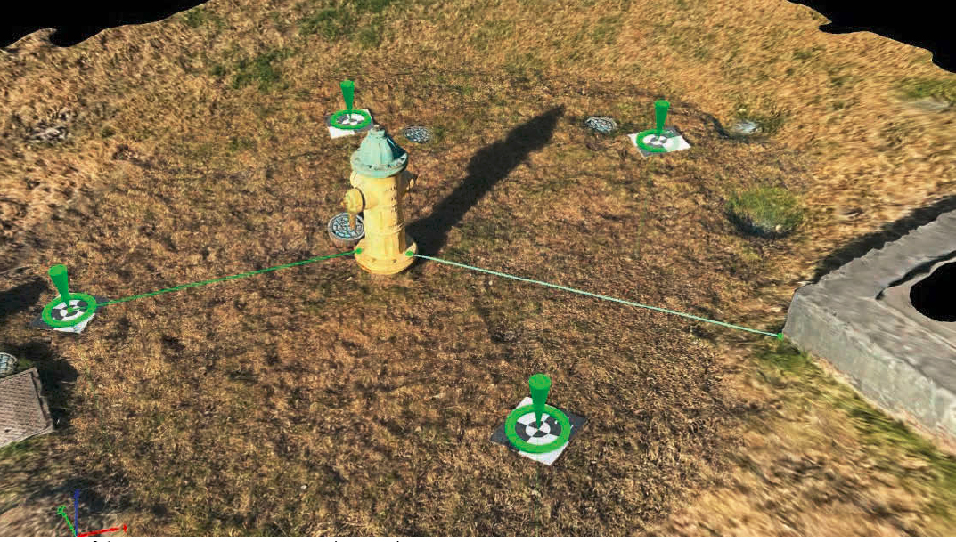
- Case 5: 3D Objects (Figure 48).
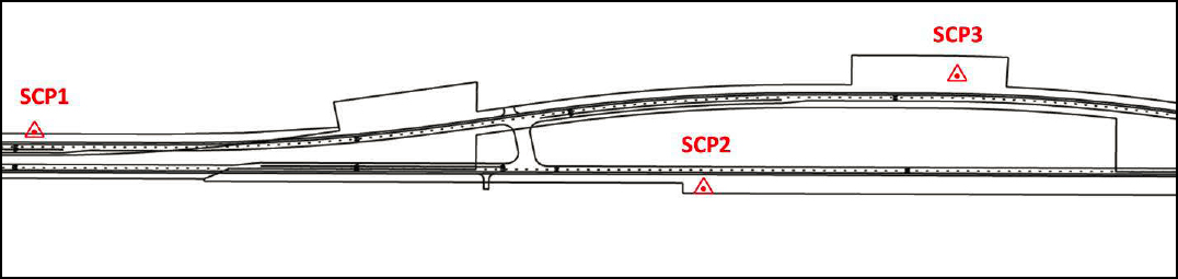
Courtesy of the Texas A&M Transportation Institute.
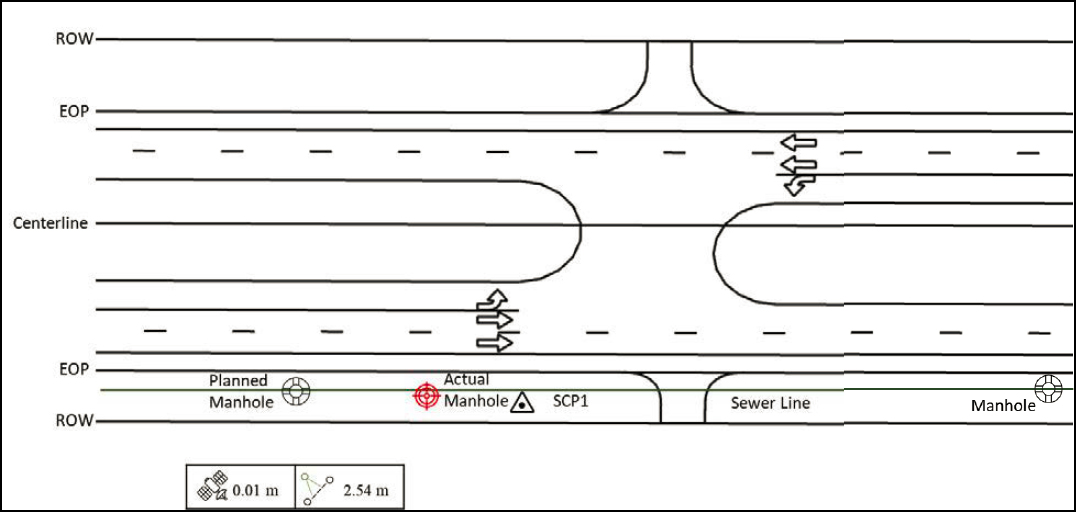
Case 1: Project Survey Control Point Verification
In this case, the inspector occupies one or more project SCPs to make sure the coordinate system parameters used for the data collection are consistent with those used for project survey control (Figure 44). This is one the first activities to complete at the job site. This case also provides an opportunity to verify the positional accuracy of the GNSS antenna by using the SCP coordinates the project surveyor has provided. The data collection procedure is as follows:
- Obtain the SCP data sheet from the project surveyor.
- Connect the GNSS antenna and establish the RTK connection.
- Occupy the SCP for at least 180 seconds. Note: This time should be adequate to verify that the GNSS antenna is adequate for the data collection.
- Verify the positional accuracy of the GNSS antenna with respect to the SCP coordinates.
- Conduct observations at the required frequency, including before starting the utility inspection and after completing the utility inspection.
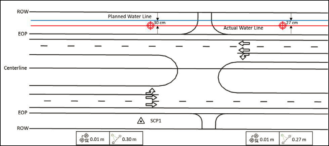
Case 2: Point Features
This case involves having a georeferenced digital representation of the plans on the mobile device and using the stakeout tool of the data collection app to find the point feature and verify whether its location is within a pre-specified tolerance (Figure 45). If the user does not have the design plans but has the planned coordinates of the point feature of interest, the stakeout tool can still be used to verify the location of the point feature.
If the location is within the required tolerance, the data collection procedure is as follows:
- Upload the digital plans to the mobile device or download them from the cloud.
- Connect the GNSS antenna and establish the RTK connection.
- Select the point feature of interest on the mobile application and use the stakeout tool to navigate and find the actual location.
- Occupy the center of the point feature and verify the actual location of the feature is within the required tolerance.
If the location is outside of the required tolerance, the data collection procedure is as follows:
- Upload the digital plans to the mobile device or download them from the cloud.
- Connect the GNSS antenna and establish the RTK connection.
- Select the point feature of interest on the mobile application and use the stakeout tool to navigate to the planned location.
- Occupy the center of the actual point feature and record its location. Make sure to associate this location with the point feature of interest.
- Measure and record the offset between the planned location and the actual ground location.
In certain cases, it is not possible to occupy the center of the point feature but documenting a point around the perimeter is feasible. For example, for utility poles, it is common to document the point at the base of the pole that is closest to the highway. Using the pole diameter, it is then possible to calculate the coordinates of the center of the base of the pole.
Case 3: Line Features
This case involves having a georeferenced digital representation of the plans on the mobile device and using the line stakeout tool of the data collection app to find the line feature and verify whether its location is within a pre-specified tolerance (Figure 46).
If the line feature is within the required tolerance, the data collection procedure is as follows:
- Upload the digital plans to the mobile device or download them from the cloud.
- Connect the GNSS antenna and establish the RTK connection.
- Select the line feature of interest on the mobile application and use the line stakeout tool to navigate and find a point along the actual line feature.
- Verify the actual location of the line feature is within the required tolerance.
If the line feature is outside of the required tolerance, the data collection procedure is as follows:
- Upload the digital plans to the mobile device or download them from the cloud.
- Connect the GNSS antenna and establish the RTK connection.
- Select the line feature of interest on the mobile application and use the line stakeout tool to navigate to the planned location.
- Occupy a point along the actual line feature and record its location. Make sure to associate this location with the line feature of interest.
- Measure the shortest distance between the actual and planned line using the offset function on the data collection application.
- As needed, repeat the previous two steps at other locations along the line feature.
The ASCE 75-22 consensus standard includes guidance regarding desired spacing between consecutive measurements for the purpose of developing as-built plans (27).
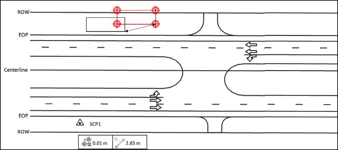
Case 4: Polygon Features
This case involves having a georeferenced digital representation of the plans on the mobile device and using the stakeout tool of the data collection app to find the corners of the polygon feature and verify whether its location is within a pre-specified tolerance (Figure 47.
If the polygon feature is within the required tolerance, the data collection procedure is as follows:
- Upload the digital plans to the mobile device or download them from the cloud.
- Connect the GNSS antenna and establish the RTK connection.
- Select a corner of the feature of interest on the mobile application and use the stakeout tool to navigate and find the actual location.
- Occupy the corner selected and verify its actual location is within the required tolerance.
- Repeat the previous two steps at the other corners.
- Measure the length of each side of the polygon feature. Note: Although the length can be calculated from the planned or observed coordinates of the corner points, using a measuring tape is a good practice and could be more accurate depending on the positional accuracy of the GNSS equipment used.
- Measure the height (or depth) of the polygon feature.
If the polygon feature is outside of the required tolerance, the data collection procedure is as follows:
- Upload the digital plans to the mobile device or download them from the cloud.
- Connect the GNSS antenna and establish the RTK connection.
- Select a corner of the feature of interest on the mobile application and use the stakeout tool to navigate and find the actual location.
- Occupy the corner selected and record its location. Make sure to associate this location with the corner and polygon feature of interest.
- Measure and record the offset between the planned location and the actual ground location.
- Repeat the previous three steps at the other corners.
- Measure the length of each side of the polygon feature. Note: Although the length can be calculated from the planned or observed coordinates of the corner points, using a measuring tape is a good practice and could be more accurate depending on the positional accuracy of the equipment used.
- Measure the height (or depth) of the polygon feature.
Case 5: 3D Objects
This case involves using a device such as a UAS or a smartphone to capture multiple images around the area of interest and processing the images using photogrammetry software (Figure 48). It may be possible to augment this capability by using LiDAR to generate point clouds and fuse the data with the results from the photogrammetric process. The result is a georeferenced 3D model of the feature of interest (and, by extension, the area surrounding the utility feature) that meets project datum requirements.
When using GCPs, the data collection procedure is as follows:
- Place a sufficient number of targets within the scene, which will become GCPs.
- Identify points that will not be used for SfM processing but will become checkpoints.
- Measure the distance between the checkpoints using a measuring tape. Distances between checkpoints will be used for validation and quality control, not as part of the SfM process.
- Connect the GNSS antenna and occupy each target for at least 180 seconds to verify the measured locations meet project datum requirements.
- If using a smartphone, use a suitable app to walk around the feature of interest and capture images automatically.
- If using a UAS, use a suitable flight plan to take an adequate number of images of the area of interest. Make sure to comply with endlap and sidelap requirements.
- Make sure GCPs are captured in the images.
- Use photogrammetry software to process the images, making sure to include GCP coordinates. Make sure to apply quality controls to verify the completeness and accuracy of the process. For example, using the software, measure distances between GCPs and compare those distances to what was measured in the field.
- Using the software, read the X-Y-Z coordinates of the feature of interest and take additional measurements as needed.
When using RTK, the data collection procedure is as follows:
- For quality control purposes:
- Place targets within the scene.
- Measure the distance between a sample of targets using a measuring tape. Distances between checkpoints will be used for validation and quality control, not as part of the SfM process.
- Connect the GNSS antenna and establish the RTK connection.
- Occupy each target for at least 180 seconds and verify the measured locations meet project datum requirements.
- If using a smartphone, use a suitable app to walk around the feature of interest and capture images automatically. Make sure images are georeferenced with RTK.
- If using a UAS, use a suitable flight plan to take an adequate number of images of the area of interest. Make sure to comply with endlap and sidelap requirements. Make sure images are georeferenced with RTK.
- Use photogrammetry software to process the images. Make sure to apply quality controls to verify the completeness and accuracy of the process. For example, using the software, measure distances between targets and compare those distances to what was measured in the field.
- Using the software, read the X-Y-Z coordinates of the feature of interest and take additional measurements as needed.
In some cases, georeferencing is not a critical requirement, but other features in the scene (e.g., sidewalk edges, building facades, or edge of pavement) can be used to provide context and enable a quick assessment. The data collection procedure is as follows:
- Identify features in the scene that can be used as “targets” and use a measuring tape to measure distances between those features. Alternatively, place flat target objects at ground level that can be captured by the images.
- If using a smartphone, use a suitable app to walk around the feature of interest and capture images automatically.
- If using a UAS, use a suitable flight plan to take an adequate number of images of the area of interest. Make sure to comply with endlap and sidelap requirements.
- Use photogrammetry software to process the images. Make sure to apply quality controls to verify the completeness and accuracy of the process. For example, using the software, measure distances between targets and compare those distances to what was measured in the field.
- Using the software, read feature dimensions and take additional measurements as needed.


