Minimizing Utility Issues During Construction: A Guide (2024)
Chapter: 4 Utility Inspection Procedures

CHAPTER 4
Utility Inspection Procedures
Data Collection Equipment and Software
A number of low-cost devices, including unmanned aircraft systems (UASs), smartphones and tablets, and external GNSS antennas, are adequate for conducting utility inspections. Most UAS applications used for inspections involve the use of small rotary platforms. Real-time kinematic (RTK) support is desirable but not essential if ground control points (GCPs) are used in the field. Recent smartphones and tablets have the capability to receive data from multiple GNSS constellations.
External GNSS antennas of interest here are devices and companion services that offer centimeter-level positional accuracy at lower costs than traditional GNSS equipment. A typical business model is one in which the cost of the GNSS antenna is low (say $500 to $5,000). The receiver provides a positional accuracy between 60 cm (2 ft) and 1.5 m (5 ft) in autonomous mode, but when connected to an RTK correction subscription service, the positional accuracy improves up to 1–3 cm horizontally and 1–10 cm vertically. RTK subscription rates range from $4,000 per year to $400 per month or $100 per day. Depending on the brand and model, GNSS receivers can connect to public RTK networks for free, but in other cases, users first must pay an unlocking or access fee to the GNSS vendor.
Mobile device data collection apps of interest are apps that enable users to complete activities such as the following:
- Upload a data dictionary to the device and collect data using preestablished feature classes and drop-down lists.
- Take pictures and videos and associate these data elements with specific features.
- Compare the location of design-level features versus what was built.
- Gather and document unstructured point, line, and polygon data.
- Collect picture sets needed for structure-from-motion (SfM) photogrammetry and the production of 3D models.
- Collect light detection and ranging (LiDAR) data needed to produce 3D models.
- Add comments.
Data Collection Protocols
Documenting offsets between planned and actual locations is critical for deciding whether to accept an installation as is or to require removal and reinstallation, and for preparing accurate, reliable as-built plans. Examples of relevant utility inspection activities include the following:
- Verify survey control. Verification of survey control involves occupying survey control points (SCPs) to ensure the data collection equipment is properly calibrated.
- Verify right-of-way line. Note: This activity is different from defining or establishing the right-of-way line, which is an activity reserved for registered surveyors. Verification of the right-of-way line in the context of this research is to make sure utility work has occurred on the correct side of the right-of-way line.
- Verify trench dimensions.
- Verify dimensions, alignment, and coordinates of pipes, conduits, and duct banks.
- For trenchless construction, inspect and verify dimensions and coordinates of boring pits, shafts, or trenches; verify coordinates of pilot holes; verify coordinates of entry and exit pipe or box locations; obtain coordinates at critical points, such as edge of pavement and bottom of ditches; and conduct comparisons with bore log data.
- Verify dimensions and coordinates of protect-in-place measures (such as concrete caps, metal plates, and plastic plates).
- Verify dimensions and coordinates of structures such as junction boxes, handholes, manholes, vaults, hydrants, valves, thrust blocks, mechanical restraints, cathodic protection components, and utility markers.
- Verify elevation of frames, grates, rings, and covers for structures such as junction boxes, handholes, and manholes.
- Verify horizontal and vertical coordinates of electric transmission towers and poles.
- Verify horizontal and vertical coordinates of distribution poles.
- Verify coordinates of utility pole attachments and utility pole assemblies.
- Verify elevation and sag of overhead utility wires.
- Verify coordinates of utility attachments to bridges.
- Verify length and coordinates of temporary erosion, sedimentation, and environmental controls, such as rock filter dams, temporary pipe slope drains, temporary paved flumes, construction exits, construction perimeter fence, sandbags, temporary sediment control fence, and biodegradable erosion control logs.
- Verify the removal of existing utility facilities from the right-of-way.
- Verify measures for out-of-service utility facilities that are allowed to remain in place (such as purging, capping, and filling with grout).
The following five basic data collection cases apply to one or more of the utility inspection activities listed above:
- Project survey control point verification (Figure 4).
- Point features (Figure 5).
- Line features (Figure 6).
- Polygon features (Figure 7).
- 3D objects (Figure 8).
Project Survey Control Point Verification
This case involves the inspector occupying one or more project SCPs to make sure the coordinate system parameters used for the data collection are consistent with those used for project survey
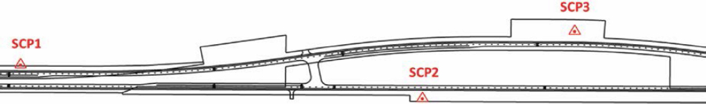
control (Figure 4). This is one of the first activities to complete at the job site. This case also provides an opportunity to verify the positional accuracy of the GNSS antenna by using the SCP coordinates the project surveyor has provided. The data collection procedure is as follows:
- Obtain the SCP data sheet from the project surveyor.
- Connect the GNSS antenna and establish the RTK connection.
- Occupy the SCP for at least 180 seconds. Note: This time should be adequate to verify that the GNSS antenna is adequate for the data collection.
- Verify the positional accuracy of the GNSS antenna with respect to the SCP coordinates.
- Conduct observations at the required frequency, including before starting the utility inspection and after completing the utility inspection.
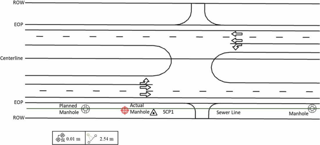
Point Features
This use case involves having a georeferenced digital representation of the plans on the mobile device and using the stakeout tool of the data collection app to find the point feature and verify whether its location is within a prespecified tolerance (Figure 5). If the user does not have the design plans but has the planned coordinates of the point feature of interest, the stakeout tool can still be used to verify the location of the point feature.
If the location is within the required tolerance, the data collection procedure is as follows:
- Upload the digital plans to the mobile device or download them from the cloud.
- Connect the GNSS antenna and establish the RTK connection.
- Select the point feature of interest on the mobile application and use the stakeout tool to navigate and find the actual location.
- Occupy the center of the point feature and verify the actual location of the feature is within the required tolerance.
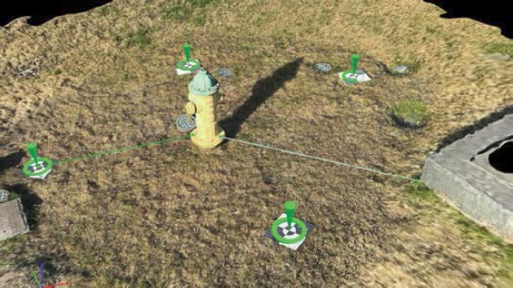
Figure 8. 3D model of utility features using photogrammetry and GCPs.
If the location is outside the required tolerance, the data collection procedure is as follows:
- Upload the digital plans to the mobile device or download them from the cloud.
- Connect the GNSS antenna and establish the RTK connection.
- Select the point feature of interest on the mobile application and use the stakeout tool to navigate to the planned location.
- Occupy the center of the actual point feature and record its location. Make sure to associate this location with the point feature of interest.
- Measure and record the offset between the planned location and the actual ground location.
In certain cases, it is not possible to occupy the center of the point feature, but documenting a point around the perimeter is feasible. For example, for utility poles, it is common to document the point at the base of the pole that is closest to the highway. Using the pole diameter, it is then possible to calculate the coordinates of the center of the base of the pole.
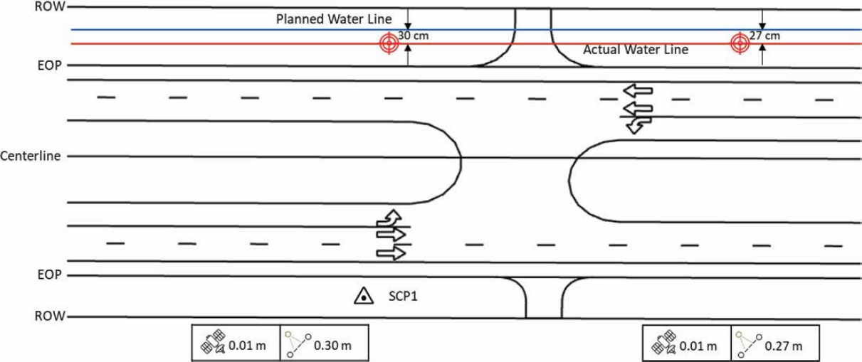
Line Features
This case involves having a georeferenced digital representation of the plans on the mobile device and using the line stakeout tool of the data collection app to find the line feature and verify whether its location is within a prespecified tolerance (Figure 6).
If the line feature is within the required tolerance, the data collection procedure is as follows:
- Upload the digital plans to the mobile device or download them from the cloud.
- Connect the GNSS antenna and establish the RTK connection.
- Select the line feature of interest on the mobile application and use the line stakeout tool to navigate and find a point along the actual line feature.
- Verify the actual location of the line feature is within the required tolerance.
If the line feature is outside the required tolerance, the data collection procedure is as follows:
- Upload the digital plans to the mobile device or download them from the cloud.
- Connect the GNSS antenna and establish the RTK connection.
- Select the line feature of interest on the mobile application and use the line stakeout tool to navigate to the planned location.
- Occupy a point along the actual line feature and record its location. Make sure to associate this location with the line feature of interest.
- Measure the shortest distance between the actual and planned line using the offset function on the data collection application.
- As needed, repeat the previous two steps at other locations along the line feature.
The ASCE 75-22 consensus standard includes guidance regarding desired spacing between consecutive measurements for the purpose of developing as-built plans.
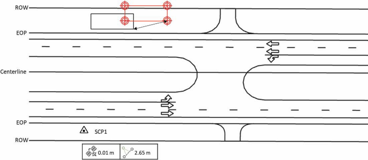
Polygon Features
This case involves having a georeferenced digital representation of the plans on the mobile device and using the stakeout tool of the data collection app to find the corners of the polygon feature and verify whether its location is within a prespecified tolerance (Figure 7).
If the polygon feature is within the required tolerance, the data collection procedure is as follows:
- Upload the digital plans to the mobile device or download them from the cloud.
- Connect the GNSS antenna and establish the RTK connection.
- Select a corner of the feature of interest on the mobile application and use the stakeout tool to navigate and find the actual location.
- Occupy the corner selected and verify its actual location is within the required tolerance.
- Repeat the previous two steps at the other corners.
- Measure the length of each side of the polygon feature. Note: Although the length can be calculated from the planned or observed coordinates of the corner points, using a measuring tape is a good practice and could be more accurate, depending on the positional accuracy of the GNSS equipment used.
- Measure the height (or depth) of the polygon feature.
If the polygon feature is outside the required tolerance, the data collection procedure is as follows:
- Upload the digital plans to the mobile device or download them from the cloud.
- Connect the GNSS antenna and establish the RTK connection.
- Select a corner of the feature of interest on the mobile application and use the stakeout tool to navigate and find the actual location.
- Occupy the corner selected and record its location. Make sure to associate this location with the corner and polygon feature of interest.
- Measure and record the offset between the planned location and the actual ground location.
- Repeat the previous three steps at the other corners.
- Measure the length of each side of the polygon feature. Note: Although the length can be calculated from the planned or observed coordinates of the corner points, using a measuring tape is a good practice and could be more accurate, depending on the positional accuracy of the equipment used.
- Measure the height (or depth) of the polygon feature.
3D Objects
This use case involves using a device such as a UAS or a smartphone to capture multiple images around the area of interest and processing the images using photogrammetry software (Figure 8). It may be possible to augment this capability by using LiDAR to generate point clouds and fuse the data with the results from the photogrammetric process. The result is a georeferenced 3D model of the feature of interest (and, by extension, the area surrounding the utility feature) that meets project datum requirements.
When using GCPs, the data collection procedure is as follows:
- Place a sufficient number of targets within the scene, which will become GCPs.
- Identify points that will not be used for SfM processing but will become checkpoints.
- Measure the distance between the checkpoints using a measuring tape. Distances between checkpoints will be used for validation and quality control, not as part of the SfM process.
- Connect the GNSS antenna and occupy each target for at least 180 seconds to verify the measured locations meet project datum requirements.
- If using a smartphone, use a suitable app to walk around the feature of interest and capture images automatically.
- If using a UAS, use a suitable flight plan to take an adequate number of images of the area of interest. Make sure to comply with endlap and sidelap requirements.
- Make sure GCPs are captured in the images.
- Use photogrammetry software to process the images, making sure to include GCP coordinates. Make sure to apply quality controls to verify the completeness and accuracy of the process. For example, using the software, measure distances between GCPs and compare those distances to what was measured in the field.
- Using the software, read the X-Y-Z coordinates of the feature of interest and take additional measurements as needed.
When using RTK, the data collection procedure is as follows:
- For quality control purposes:
- Place targets within the scene.
- Measure the distance between a sample of targets using a measuring tape. Distances between checkpoints will be used for validation and quality control, not as part of the SfM process.
- Connect the GNSS antenna and establish the RTK connection.
- Occupy each target for at least 180 seconds and verify the measured locations meet project datum requirements.
- If using a smartphone, use a suitable app to walk around the feature of interest and capture images automatically. Make sure images are georeferenced with RTK.
- If using a UAS, use a suitable flight plan to take an adequate number of images of the area of interest. Make sure to comply with endlap and sidelap requirements. Make sure images are georeferenced with RTK.
- Use photogrammetry software to process the images. Make sure to apply quality controls to verify the completeness and accuracy of the process. For example, using the software, measure distances between targets and compare those distances to what was measured in the field.
- Using the software, read the X-Y-Z coordinates of the feature of interest and take additional measurements as needed.
In some cases, georeferencing is not a critical requirement, but other features in the scene (e.g., sidewalk edges, building facades, or edge of pavement) can be used to provide context and enable a quick assessment. The data collection procedure is as follows:
- Identify features in the scene that can be used as “targets” and use a measuring tape to measure distances between those features. Alternatively, place flat target objects at ground level that can be captured by the images.
- If using a smartphone, use a suitable app to walk around the feature of interest and capture images automatically.
- If using a UAS, use a suitable flight plan to take an adequate number of images of the area of interest. Make sure to comply with endlap and sidelap requirements.
- Use photogrammetry software to process the images. Make sure to apply quality controls to verify the completeness and accuracy of the process. For example, using the software, measure distances between targets and compare those distances to what was measured in the field.
- Using the software, read feature dimensions and take additional measurements as needed.


