Developing a Guide for On-Bridge Stormwater Treatment Practices (2024)
Chapter: Appendix B: Task 1b Memorandum: Development and Assessment of On-Bridge Stormwater Treatment BMPs
Contents
Overview of Design Methodology and Memorandum Organization
2. CHARACTERIZATION OF BRIDGE SETTING FOR STORMWATER TREATMENT
Substructure and Superstructure Characteristics
Maintenance Regimes for Drainage Infrastructure
3. EVALUATION OF DESIGN REQUIREMENTS AND APPROACH
Tier 2: Primary Design Factors
Tier 1+2: Assessment of Potential BMP Locations
Tier 3: Supporting Design Factors
4. DESIGN CASE STUDIES AND ALTERNATIVES EVALUATION
Case Study 1—GDOT State Route 3 over Peachtree Creek
Case Study 2— GDOT County Road 130 over White Oak Creek
Case Study 3—MnDOT Interstate 90 over Mississippi River
5. SYNTHESIS, RECOMMENDATIONS, AND RESEARCH NEEDS
Glossary of Key Terms
Common Parts of a Bridge
Substructure – a general term referring to the piers and abutments that lie between the bridge foundation and the superstructure.
Superstructure – a general term referring to the girders, beams, deck, shoulders, edge barriers, towers (if applicable) other supporting elements above the substructure that support the riding surface of the bridge.
Span – refers to lengths of bridge between substructure elements. Span is also used to refer to specific elements, such as the “center span” of a bridge.
Abutments – the substructure elements at either end of a bridge where the bridge connects to land. A multi-part bridge may have abutments at intermediate points where the bridge connects to land.
Bents (aka piers) – a vertical part of the substructure located between the ends of a bridge. They are typically made up of two or more columns connected at their topmost ends by a cap.
Bent cap – a horizontal member that spans the bents and serves as the support for the girders.
Piers (aka bents) – a type of bent that consists of a single column.
Beam – a general term for an approximately horizontal structural element that supports the bridge deck. Girders and cross beams are common types of beams in a bridge design. Note, due to the unique geometries of bridges, it is rare for elements to be truly horizontal. In this memo, horizontal refers to a general direct, not a perfect horizontal plane.
Girders – a horizontal structural element that runs between piers or bents in the direction of the roadway. A girder is a type of beam.
Cross beam – a horizontal structural element that typically runs between girders to support the bridge deck. These are often parallel or angled relative to the direction of the roadway.
Deck – the structural platform that spans the girders and cross beams and serves as the surface of the bridge. The deck is a structural element. This includes the travel lanes and the shoulders and can also include sidewalks or multi-use paths.
Parapet (aka solid barrier) - A railing system made of reinforced concrete along the outside edge of a bridge deck used to help protect vehicles and pedestrians.
Guard rail – a simple open type of edge barrier.
Edge barrier – a general term used to refer to the barrier(s) at the outer edges of the bridge that to help prevent vehicles or pedestrians from going over the sides. This is distinct from a center barrier which separates opposing traffic between two sides of a bridge.
Center barrier – a general term to refer to the barrier(s) between lanes of traffic. These are not at an outer edge of a bridge.
Deck drains – openings that pass through the bridge deck to convey stormwater runoff.
Side drains – openings that pass through the edge barrier of the bridge to convey stormwater runoff.
Related Design and Operation and Maintenance (O&M) Terms
Base flood elevation -refers to the 100-year peak water surface elevation defined by the Federal Emergency Management Agency.
Floodway – the channel and adjacent overbank areas necessary to effectively convey floodwaters.
Floodplain – the floodway and the floodplain fringe that is inundated in the 100-year base flood event.
Vertical clearance – a general term used to refer to the vertical separation between the bottom of the bridge beams and the maximum height that is needed to safely pass vehicles (ships/boats/trains/trucks, etc.) below the bridge. This could be driven by the base flood elevation, navigability requirements, or rail/traffic requirements.
Drainage criteria (aka, storm drainage) – a general term referring to the requirements for draining stormwater from a bridge during storms for the purpose of vehicular safety. Drainage criteria typically include the return interval storm event, the allowable lateral spread, and/or other criteria to define the size and spacing of drainage elements.
Water quality flows – the flowrate generated from a regulatory water quality treatment event, such as the flow generated from the 85th percentile storm event, or the flow required to treat a certain percentage of long-term runoff volume. Water quality flows are nearly always smaller than the storm flows relevant for drainage criteria.
Constructability – refers to the relative complexity and cost required to construct a design.
O&M, including inspection, routine maintenance, and major/rehabilitative maintenance.
Structural issues – in this memorandum refers to the potential for a best management practices (BMP) design to compromise the structural integrity of a bridge.
Clogging lifespan – the time that a media filter can operate at or above its design infiltration rate between rehabilitation or media replacement events.
Maintenance interval – the time interval at which maintenance activities are required to provide ongoing function of a BMP. This includes both routine and rehabilitative maintenance. For a media filtration BMP, this may include sediment removal, debris removal, media replacement, or other activities.
Inspection interval – the time interval at which a BMP should be visually observed and/or tested to evaluate function and need for maintenance.
Under-bridge inspection equipment - refers to a type of lift, boom, or platform trucks designed to allow work below the bridge deck via a truck parked on the bridge surface. For example, inspection personnel ride in a bucket. (example: https://paxton-mitchell.com) or walk on a temporary walkway below the bridge. (example: https://andersonunderbridge.com/).
Traditional hoist – refers to a truck-mounted boom lift system that can extend over the side of a bridge and lift vertically.
Vacuum truck – a truck with an extendable hose attached to a boom that is designed to pick up and transfer liquids, slurries, and loose aggregates into a tank mounted on the truck.
Manual labor – refers to hand labor, such as use of shovels, raking of or replacing media, carrying of bags, or other similar activities.
1. Introduction
This memorandum (Memo) summarizes the findings of Task 1b of NCHRP Project 25-61. The overall goal of the project is to develop guidelines for implementing effective and practical stormwater treatment devices to remove pollutants from highway runoff within the physical and operational constraints of the bridge environment and before it reaches receiving waters. Task 1b focused on developing and evaluating conceptual BMP designs that could be constructed on bridges to treat stormwater runoff.
Task 1a included an assessment of stormwater treatment processes, specifically filter media blends, potentially suitable for this environment. This includes media blend that are suitable for rapid treatment in a small footprint. The findings from Task 1a and Task 1b are integrated in the Phase I Interim Report.
Overview of Design Methodology and Memorandum Organization
Our overall approach for Task 1b included the following steps:
- Characterize the bridge environment (Section 2). We sought to determine the typical ranges of physical conditions and design and operational constraints that affect BMP design, construction, and O&M in the bridge environment. We conducted interviews with state departments of transportation (DOTs), obtained case studies, reviewed typical design criteria, and conducted rapid on-line and in-person visual surveys.
- Develop and prioritize design requirements (Section 3). We reviewed the range of BMP design requirements and constraints and sought to prioritize their relative importance and impact on the design process. As part of this process, we also began to develop design parameters and alternatives to address each requirement or constraint.
- Conduct design case studies (Section 4). We applied potential BMP designs to real bridge designs obtained from DOTs. We used these case studies to further develop and evaluate design alternatives when applied to example bridges.
- Synthesize design recommendations, research needs, and next steps (Section 5). We synthesized design recommendations based on the findings from Section 2, 3, and 4. From this review, we also identified the aspects of the design process that are (1) most important for successful BMP designs in the bridge environment, and (2) least supported by available scientific or practical experience so that these can potentially be prioritized for potential new research.
This memo focuses on BMP retrofits within existing constructed bridges. This is the most challenging and constrained condition and is also likely the most common condition encountered by DOTs due to the number of existing bridges versus new bridge projects. Implementation of BMPs on new bridges would encounter many of the same design constraints and challenges but may have some additional flexibility to incorporate BMPs into the design.
2. Characterization of Bridge Setting for Stormwater Treatment
Methodology
Bridge designs across the country vary in numerous ways as a result of differences in design standards (varying by DOT and by vintage of construction), site conditions, designer preferences, and many other factors. This task sought to characterize representative ranges of physical conditions, design approaches, and operational constraints that exist in the bridge environment. This served as a foundation for
development of potential BMP designs. However, it should be noted that in this task we do not define the entire range of conditions that exist.
We conducted several lines of research to support this characterization:
- The research team conducted interviews with staff from four DOTs representing design, construction, maintenance, hydraulics, and environmental services. The DOTs were selected from the east, west, south, and north (Virginia DOT, Washington DOT, Georgia DOT, and Minnesota DOT respectively). In preparation for the interviews, the team reviewed available documentation from the DOT’s bridge design criteria and guidelines as well as drainage design manuals. The principal objective of the interviews was to define the typical structural, drainage, and O&M conditions that exist on bridges based upon the design criteria and guidelines, in order to develop BMP options that provide water quality treatment while also meeting design requirements.
- The research team acquired “as-built” construction plans of several bridges from the DOTs interviewed to further assess potential opportunities and constraints for BMP retrofits. We then used these examples to evaluate the typical conditions and criteria for on-bridge BMPs described in Section 3. We also used a subset of the as-built plans as the basis for the design case studies presented in Section 4.
- The research team conducted virtual site visits using “Street View” by Google Maps to observe and review bridge conditions, with a specific focus on existing drainage systems and delivery of runoff to receiving waters.
- The research team used previous NCHRP tools and consulted representative highway drainage manuals to evaluate potential sizing requirements for conveyance elements and water quality treatment BMPs.
Based on the research and interviews, the following subsections summarize a representative range of conditions and criteria which are relevant to the implementation of retrofit on-bridge BMPs. Although there are commonalities among highway bridges in the US, each bridge is designed for its unique circumstances. This characterization is not exhaustive or conclusive.
Substructure and Superstructure Characteristics
The structure of a bridge will highly influence the implementation of BMPs including the ability to mount conveyance elements and BMPs to structural elements and the applicable locations that may be suitable for a BMP in each bridge type. Bridge elements have differing suitability for BMP retrofits based on their structural characteristics. Substructure elements, such as a bridge bent or pier, are typically designed to carry large loads with safety factors and the additional structural load of a BMP can be relatively small in comparison. The superstructure elements (girders or beams) are also typically designed for large loads where the weight of a BMP could be relatively small, however each individual beam carries much less load than a typical bent or pier. Bridge edge barriers often carry a lower design load. Key aspects of the bridge structural design that may affect BMP retrofits options are listed below.
- Structural design standards and policy. Structural design criteria have changed over time since bridges were built. While newer bridges may have adequate surplus load carrying capacity to accept the weight of a BMP, older bridges may already be deficient with respect to current structural design standards. It is possible that modifications to structural elements of bridges would trigger the need to update the bridge to current structural design standards. DOTs may have various policies regarding structural modifications to existing bridges.
- Pier layout. The spacing and location of bridge piers or bents is a key variable that differs greatly between bridges. This affects how much drainage area could potentially be routed to a BMP located at a pier or bent.
- Flood clearance. The peak flood elevation relative to the bridge elevation is a factor in whether a BMP can be attached to a pier or below a girder and still be located above the base flood elevation. Our understanding is that some bridges are built with the lower edge of the girder (i.e., the lower chord) immediately above the base flood elevation while others provide greater clearance above the base flood.
- Other clearance issues. We understand that other factors often dictate bridge height, including navigation, rail or traffic passage. Required clearance would differ for different parts of a bridge; for example, clearance for watercraft may only be required at a center span and not apply near piers or for side spans.
- Girder type and section. Bridge girders are commonly constructed of steel or reinforced concrete. The cross sections of these girders, placement of girders, and the structural elements between girders varies by bridge. In some cases, a grid configuration of girders and cross beams may exist that limits the clear space between girders. Diagonal beam and girder arrays are also relatively common, which provide irregularly shaped areas.
- Edge barriers. Edge barrier designs vary greatly, including solid barriers and a variety of open or partly open barriers. These are designed to resist impact from automobiles but may have a wide range of structural properties.
Attachment 1 shows a subsample of bridge types, including bridges where imagery was available from the deck and from below. The structure types provided in Attachment 1 and the case studies (Section 4) are a sampling of the variety that exists. Although not exhaustive, this sample does represent common bridge types and facilitates evaluation of typical bridge conditions.
Drainage Areas
Drainage area sizes on bridges vary but are often very small with tightly spaced drains to facilitate quickly moving water off the bridge deck to maintain safe roadway conditions. The smallest drainage area to individual drains in our case studies was less than 100 square feet, but we found that sizes can range up to 10,000 square feet. The size and spacing of deck drains (described below) and the drainage criteria (also described below) are directly correlated to the size of the drainage areas and width of the curbed shoulder. For bridges that have open rails or tightly spaced scupper drains the discharge is effectively continuous along the length of the bridge. The number of drains on a given bridge could vary from around four to more than 50 given bridge configuration and length. For example, there were 96 deck drains on the SR3 case study bridge, which is only 220 feet long.
Bridge Drainage Methods
Based on our review of example bridges, we found that there are approximately four categories of bridge drainage, discussed below.
Surface Flow to Abutments
In this configuration, a curb or solid edge barrier is continuous along the bridge span without drains. Water is collected in drains located past the end of the bridge or is allowed to flow under a guardrail past
the end of the bridge. This type of bridge is not the subject of this research as BMPs can be located on land. We found that this is very common for shorter bridges less than about 300 feet long. Presumably this decision is based on the ability to meet drainage criteria, which depends on slope, shoulder width, and other factors.
Deck Drains and Side Drains
This configuration is common on longer bridges, and also relatively common on shorter and flatter bridges where drainage criteria do not support routing to land. This is a primary topic of this research.
Stormwater drainage is performed by various systems of deck drains or side drains. Definitions of these terms appear to vary, but herein, the term “deck drain” will be used as the general term to refer to water flowing vertically through the bridge deck, and “side drain” will refer to water flowing laterally off the side of the deck. There does not appear to be a consistent approach for drainage used within a given DOT or between DOTs.
For bridges with deck drains, the most common approaches appear to be circular openings through the deck, typically 4 inches to 6 inches in diameter. These are spaced relatively closely (often 5 to 50 feet apart). Some are lined with a pipe segment that extends below the deck. These may connect to a pipe system below the deck or freefall from the end of the pie. Others deck drains are simply a hole through the deck. Deck drains can also include small rectangular or square grated drop inlets, often around 12 inches in width dimension. Overall, we found that openings in the deck exceeding about 1 foot are very rare, even if grated. This is likely a design decision to limit the impact of the drains on structural design, as the most common deck drain dimensions can typically be fit between strands of rebar reinforcement. It is relatively rare in over-water spans for water to be collected and piped after passing through the deck drains, however we did identify some conditions where this occurs. It appears to be more common where parts of the bridge are over land and there is another roadway or railway below the bridge.
Side drains can be spaced at intervals similar to deck drains (via openings in barriers or curbs). These typically simply flow off the edge of the bridge. We did not observe a case where water is captured and conveyed to a central location when there were side drains.
Open Edge Barrier
In some bridges, water flows off the edge of pavement via an open edge barrier. There are no defined drains. This is a primary topic of this research. We did not observe any cases where a gutter is used to collect and convey water to a central location after it flows off a bridge deck.
Open-grated Bridge Deck
While this appears to be uncommon for newer bridges, there are older bridges where the deck of the bridge is constructed of open metal grate. Water passes directly through the bridge deck. There are no defined drains. This is not a topic of this research as it would be nearly impossible to collect and treat runoff in this case.
The general types of deck drain systems are described further in the Conveyance System subsection of Section 3 and illustrated in Attachment 1.
Drainage Criteria
Bridge drainage design criteria varies by state DOTs and are influenced by regional precipitation patterns with the intent of preventing gutter spread that may impact the traveling public. Typical design drainage from a bridge deck is typically based on the peak flow from a 10-year to 25-year recurrence interval precipitation intensity. This may be calculated via rational method based on a given design intensity or via generation of a hydrograph from a design storm. Regardless of specific criteria and calculation methods, the hydraulic requirement for bridge drainage is much larger than the design flow for water quality treatment, which is typically a smaller, more frequent design storm or intensity. Given that bridges were built at different times in history, it is not guaranteed that the original drainage design meets the current drainage requirements of a DOT. It is considered essential that any modifications to bridges do not reduce the drainage capacity below the current drainage design criteria. It is possible that bridge modifications could potentially trigger upgrades to meet current drainage criteria.
Maintenance Regimes for Drainage Infrastructure
Bridge maintenance requirements and practice related to stormwater drainage and BMPs varies by state, region, and traffic volume. Variables that affect the O&M schedule include potential for deicing grit, sediment, trash, and debris which contribute to clogging of deck drains and drainage pipes. The use of grit is common to help improve traction and the efficacy of pavement deicers, especially on bridges (which tend to be highly managed due to their propensity to have more severe icing issues as compared to normal roadways). Sediment can be contributed by a variety of sources including aerial deposition, construction, and traffic volumes – all factors subject to site-specific variability.
DOT staff interviewed stated that the level of effort to conduct regular O&M of current drainage systems put a strain on limited staffing and funding resources, forcing DOTs to develop a prioritization strategy. Typically bridge drainage infrastructure is maintained annually for highest priority bridges, and lower priority bridges on a frequency of up to every 5 years. DOT staff mentioned that, for certain bridges, drains and pipes often become clogged even with annual maintenance.
The accumulations of grit, sediment, trash, and debris will affect BMP performance and are a significant factor for on-bridge BMP implementation. DOTs in cold climates that apply large quantities deicing grit seasonally noted that annual or more frequent maintenance is needed.
Overall, the existing maintenance programs to remove sediment and debris from drainage systems (at a 1- to 5-year interval) provide the most similar reference point for the timing, equipment and personnel needed to maintain an on-bridge BMP. However, based on interviews with DOT staff, this maintenance program is considerably different than what would be needed to maintain on-bridge BMPs: crews do not typically need to access below the bridge deck, do not operate boom trucks for under-bridge or over-edge work, are typically removing bulk material for disposal or using drain jetting equipment to clear drains, and are not bring material to the site to replace spent material. Given the substantial difference in time requirements, equipment requirements, and specialty supplies compared to what would be needed to maintain on-bridge BMPs, it appears clear that on-bridge BMPs would require a new or substantially modified maintenance program compared to the O&M programs that currently exist.
DOT staff interviewed stated that lane closures are normally needed to maintain bridge drainage infrastructure and therefore DOTs are experienced in this. However, in high traffic bridges, lane closures are done at night. Therefore, maintenance activities are requiring lane closure require appropriate safety provisions to be performed at night.
Inspection and maintenance activities are required at various intervals for other aspects of bridge operation, such as structural inspections, painting, repaving, and other operations. We did not research these
in detail. However, this suggests that DOT maintenance crews are generally familiar with the equipment needed to access various parts of a bridges. However, it should be noted that personnel tasked with structural inspections may often be different than those tasked with O&M of the drainage systems.
Summary
We found that bridges have some general commonalities:
- Most parts of a bridge serve a structural purpose and are an integral part of the original structural design.
- Space is nearly always constrained in the bridge environment. The types, shapes, and sizes of space available differ greatly between bridges based on their unique designs.
- Drainage elements are often much smaller and more tightly spaced that normal highway drainage approaches.
- Bridges face various vertical constraints related to flood elevation and other clearance requirements.
- O&M of bridge drainage infrastructure is currently a relatively high burden for DOTs and requires disproportionate effort relative to other parts of highway O&M due to the need to work in a constrained environment.
- DOTs are experienced in performing stormwater drainage system O&M in the bridge environment. However, existing maintenance regimes are far less intensive than would be needed to inspect and maintain on-bridge BMPs.
Beyond these commonalities, there are a wide range of conditions encountered. Our overall finding is that each bridge can be quite unique, and there are a very large number of combinations of conditions encountered in the bridge environment that may influence BMP feasibility, placement, design, and O&M. The rest of this memorandum focuses on design approaches for determining where a BMP could be placed and how it could be designed to meet various needs. However, given the range of site-specific factors that need to be considered, we believe it is unlikely that a set of standard designs that address all conditions will be possible for BMPs in the bridge environment.
3. Evaluation of Design Requirements and Approach
Introduction
There are many challenges to implementing on-bridge retrofit BMPs which leads to the conclusion that, wherever possible, stormwater should be routed to the abutments or adjacent areas where BMPs can be installed and maintained on the ground. This is consistent with the finding of NCHRP Report 778 Bridge Stormwater Runoff Analysis and Treatment Options. However, consistent with the research statement for the current project, our research is focused on addressing circumstances where on-bridge BMPs are required as a retrofit, and BMPs cannot be implemented on adjacent land or otherwise replaced with off-site alternatives.
When considering retrofits in the bridge environment, different design constraints can have different impacts on the design process. As part of this project, we went through an effort of prioritizing design constraints into three tiers:
- Tier 1: Baseline Assumptions. These are relatively rigid constraints that serve as starting assumptions for the design process. These are overriding criteria that render BMPs infeasible if they cannot be satisfied.
- Tier 2: Primary Design Factors. These are key macro-level design factors that dictate the overall design approach that may be feasible.
- Tier 3: Supporting Design Factors. These are detailed aspects of the design that can be developed after the overall design feasibility is established. In some cases, these may have the effect of rendering a design infeasible. However, more often these are design details that must be worked through to produce a constructable and maintainable design.
The following sections are organized into these tiers.
Tier 1: Baseline Assumptions
Based on interviews with DOTs, review of case studies, and the professional experience of the research team, we established the following baseline constraints and assumptions for the design process.
No Modification of Bridge Deck or Structural Elements
Modifications to the bridge deck or other structure elements should be avoided. In most cases, the deck is an integral part of the structure. Increasing the size of openings may impact the structural capacity of the bridge structure, since it is likely that some amount of rebar would have to be removed. Furthermore, breaching the deck by installing a BMP can provide a route for water intrusion and significant potential for introducing corrosion into the structure. In some cases, modification of an existing structural design may be strictly prohibited by DOT policy. Even if this is possible from a policy perspective, it would typically have a disproportionate cost for structural design review to determine acceptability, and it may require structural modifications. In some cases, it may not be possible to mitigate structural risks.
This starting assumption means that the current drainage openings in the deck of the bridge cannot be expanded as part of a retrofit. This also precludes the construction of new access points through the bridge deck to support O&M access to areas below the bridge.
Figure 1 shows an example of the rebar spacing in a bridge deck, illustrating the barriers to increasing the size of deck drains in either retrofit or new bridges, or providing access via the bridge deck.

Inadequate Space for BMPs within Deck Drains
Based on the findings from the Task 1a memorandum, treatment of runoff using media filtration is needed to address the highway pollutants of concern in a reasonably constrained footprint. Media filtration has a certain minimum footprint below which this treatment approach becomes unworkable due to diminished treatment and excessive maintenance (discussed further in the BMP Sizing section).
Building on the “bridge scupper treatment concept” in NCHRP Report 778 Bridge Stormwater Runoff Analysis and Treatment Options, the possibility of retrofitting existing deck drainage inlets was evaluated since the deck penetrations were designed into the bridge and stormwater is already routed there for catchment. Although deck drains vary by bridge type and drainage needs, BMP sizing to provide media filtration of typical drainage areas is at least an order of magnitude larger than could be installed within typical deck drains as shown in the BMP Sizing section. However, piping can potentially be connected to the drains, or the existing piping can be modified, to route stormwater to a BMP mounted elsewhere on the bridge structure.
No Reduction in Hydraulic Capacity of Existing Drainage System
Any reduction in hydraulic capacity of the storm drainage system would potentially increase the risk of lateral spread across the roadway. Given that bridges were designed at different points in history, and given that climate patterns are presently changing, an existing bridge drainage system may not have excess capacity to meet current and future drainage needs. Through site-specific analysis, designers could find that in some cases there is excess drainage capacity, and some reduction to existing hydraulic capacity is tolerable. However, our assessment is that this is likely to be rare and should not be assumed for the purpose of design development. As this pertains to BMP design, this means:
- Any modification of the drainage system to support routing to a BMP must not increase the risk of clogging the drainage system.
- The conveyance system and BMP must have an overflow such that the existing peak flow drainage capacity is maintained even if the BMP becomes fully clogged.
- There should be no reduction in the number of inlets as a means of concentrating flow to a BMP. Therefore, any method of concentrating flow to a BMP location should occur via a collection system located below the elevation of the bridge deck.
Safe and Feasible Operation and Maintenance Access with Available Equipment
BMPs require regular inspection and maintenance. Regardless of whether this is needed annually or every 5 years, DOTs will face a high impact to lifecycle BMP costs if maintenance of the BMPs requires overly specialized equipment, closing of traffic lanes, or requires specialized contractor services. For the purposes of design alternatives, we made the following baseline assumptions.
- We assumed that maintenance access via boat is unlikely to be cost-effective or desirable, and for some water bodies would not be technically feasible (e.g., unnavigable rivers, streams, or wetlands, fast moving water).
- We assumed that the BMP design must allow access to the top of the media bed surface to allow media scraping and replacement without removing the entire BMP.
- We assumed that it is not feasible for O&M workers to carry bags of media on ladders or stairs.
Beyond these starting assumptions, DOTs will need to assess the availability and capabilities of maintenance equipment to perform under-bridge BMP inspection and maintenance. While bridge inspection equipment may allow observation of most parts of a bridge, the need to access media for inspection and the need to transport media for replacement does not have an analog in current bridge maintenance and will require new or greatly adapted maintenance paradigms.
Implications for Design Development
These Tier 1 factors primarily serve to narrow the range of locations within the bridge environment where a BMP may possibly be installed. These support the following initial conclusions:
- With the exception of permeable friction course (which is not the subject of this research), BMPs must be installed below the bridge deck or on the side of the bridge, also below the surface elevation of the bridge deck.
- Because the number of discharge points is typically large, it may be infeasible or pose a prohibitive O&M burden to install BMPs at each drain. Consequently, BMPs will generally require a conveyance system below or adjacent to the bridge deck to convey the water to a more central location for treatment. The team originally envisioned the development of two BMP designs, one for deck drains and one for side drains. Since a conveyance system is required for both, only one BMP design is proposed.
- The location for the BMP needs to be determined based on evaluation of structural risks, routing of flows, access for inspection and maintenance, and constructability.
Three primary BMP locations were identified and evaluated including (1) attached to the substructure (i.e., bents or piers), (2) suspended from the superstructure (i.e., beams or girders), and (3) outside of the edge barrier (guard rail). A conveyance system is typically required to carry stormwater from the existing deck drains to the BMP location, as discussed in Conveyance System section. Each of the installation locations has challenges related to O&M, including access, personnel safety, flow impairment, and winter conditions. These are considered as Tier 2 parameters.
Tier 2: Primary Design Factors
As discussed above, the most significant design decision is the location of the BMP. The location must balance structural risks, conveyance needs, constructability, and maintenance access. The decision of where to locate the BMP will then dictate much of the rest of the design process. Tier 2 design factors are primarily intended to help a design team arrive at the preferred BMP location. These factors include:
- BMP sizing: How large of system needs to be installed? This influences the size and weight of the system, which in turn influences the opportunities for placement.
- Floodway and other clearance impacts: Can the BMPs extend below the lower edge of the bridge girders? What analysis is needed to determine this?
- Conveyance: What options are feasible to centralize water to a BMP without reducing drainage capacity? This influences what locations are feasible and how complex the conveyance system would need to be.
- Relative structural risks: What locations could reasonably support the weight of the BMP and have the greatest chance of being deemed acceptable via structural review?
- Accessibility for construction and O&M: What locations can be safely accessible for construction and O&M with typical bridge maintenance equipment? This must further consider the unique maintenance requirements for BMPs compared to other current aspects of bridge maintenance.
Evaluation of each of these factors is discussed further below.
BMP Sizing
Building upon NCHRP Report 778 and the Task 1a memorandum, the basic design of the BMP is assumed to be a vertical downflow media filter box configuration filled, including specialized permeable media designed to remove the target pollutants at a relatively high media filtration rate (50 inches per hour). To develop a conceptual range of sizes for purposes of this research, we assumed a minimum of 18 inches depth of media is needed to achieve pollutant removal, 6 inches of depth is needed for an underdrainage and outlet, and at least 6 inches of depth is needed for influent headspace above the media. This sums to an overall BMP height of approximately 30 inches. These dimensions can be studied further; however, they are relatively well constrained at this time. A difference of 12 inches in this profile would have relatively limited impact on decisions about BMP siting.
Other media filtration design configurations have been developed by product vendors (e.g., radial flow used in the Contech Stormwater Management StormFilter®, upflow used in the Hydro International Up-Flo® Filter, horizontal and radial flow used in the BioClean Modular Wetlands® system). These orientations may provide some marginal reduction in required size. However, these innovative flow configurations are often protected by patents and therefore may need to be purchased and adapted for use on a bridge. Therefore, for the purpose of developing initial sizing requirements, we have assumed vertical downflow media filtration.
Within this paradigm, the BMP footprint is a key parameter in BMP sizing. Regardless of media depth, the footprint of a BMP is directly proportional to the treatment flowrate and is inversely proportional to the clogging risk. However, as size increases, so does the BMP weight and the ability to fit the BMP within the bridge environment. As such, sizing is effectively a tradeoff design decision between the amount of runoff treated, expected time to clogging, treatment performance of water treated, weight of the BMP, and size of the BMP.
To develop a range of potential sizes for design development, we conducted a preliminary sizing analysis. Key assumptions for this analysis include:
- We assumed that it would typically be infeasible to provide detention storage within the bridge environment, as this would add more weight and space requirements. Therefore, BMPs were sized in a flow-based configuration where they are designed to treat runoff at the rate it arrives.
- We developed treatment flowrates to treat 50 percent, 80 percent, and 90 percent of average annual runoff volume for various climate regions (percent runoff capture; often referred to as percent capture) A long-term treatment goal of 80 to 90 percent of average annual runoff typically underlies local water quality sizing requirements. A target of 50 percent would represent a case where there is not enough space to fully meet the water quality sizing goals that are typical, but there is still the goal of treating a meaningful fraction of runoff. To perform these calculations, we utilized the results of the NCHRP Report 778 BMP Performance Evaluation tools. This tool is based on analysis of 10 to 15 years of 5-minute resolution precipitation data; therefore, the sizing accounts for high-intensity, short-duration precipitation. We assumed a time of concentration of 5 minutes with a 100 percent impervious tributary area.
- We then translated the flowrates to media bed footprints. Based on the results of Task 1a, we assumed a design media filtration rate of 50 inches per hour. This is reasonably supported by available literature. We assumed the initial media rate would start higher than this rate to allow clogging to progress over the design maintenance interval before it would reduce treatment performance below 50 inches per hour.
- We used the results of NCHRP Report 922 (specifically the Roadside BMP Clogging Risk Assessment Tool) to estimate the media bed size needed for a one-year maintenance interval. The following key assumptions were used:
- We assumed 2 pounds per square foot of total suspended solids would result in clogging. This was studied in NCHRP Report 922. Separate studies of StormFilter Cartridges support this as a general assumption (Personal communication, James Lenhart). These estimates are relatively uncertain but serve as an approximate order of magnitude estimate.
- As part of clogging calculations, we assumed a roadway total suspended solids concentration of 70 mg/L based on the NCHRP Report 792, which is based on the Highway Runoff Database (Granato and Cazenas, 2009; Smith and Granato, 2010).
- This does not account specifically for deicing grit, which may result in much greater quantities of sediment. Deicing grit tends to be relatively coarse and may pose a greater issue of filling the headspace of the filter rather than reducing permeability. However, this issue would also tend to require a shorter maintenance interval.
- This also does not account for organic loading factors, such as macerated leaves which can result in different dynamics regarding media bed clogging.
Table 1 summarizes key precipitation statistics for US climate regions, per NCHRP Report 792.
Table 1. Precipitation statistics for various US climate regions
| Airport | Representative Region | Average Annual Rainfall Depth, inches | Design Precipitation Intensities for Target Capture Efficiency at 5-minute Time of Concentration | ||
|---|---|---|---|---|---|
| 50% of annual runoff treated | 80% of annual runoff treated | 90% of annual runoff treated | |||
| Seattle | Pacific Northwest | 40 | 0.09 | 0.16 | 0.23 |
| San Francisco | Central California | 20 | 0.1 | 0.18 | 0.29 |
| Atlanta | Southeast | 49 | 0.17 | 0.64 | 1.27 |
| Minneapolis | Upper Midwest | 28 | 0.16 | 0.62 | 1.2 |
| Washington DC | Mid-Atlantic | 40 | 0.14 | 0.48 | 1 |
| New York City | Upper Atlantic | 37 | 0.15 | 0.48 | 0.95 |
| Boise | Intermountain West | 12 | 0.1 | 0.17 | 0.29 |
| Boston | New England | 43 | 0.12 | 0.28 | 0.52 |
Table 2 shows the BMP footprint area (i.e., length multiplied by width) that would be required in various climate regions in the US based on different capture percentages as well as the estimated clogging interval.
Table 2. BMP footprint calculations for various US climate regions based on various sizing goals
| City | Representative Climate Region | BMP Footprint per Acre of Bridge Drainage, sq-ft/ac | Footprint needed for approx. 1-year clogging interval, sq-ft/ac | ||
|---|---|---|---|---|---|
| 50% capture | 80% capture | 90% capture | |||
| Seattle | Pacific Northwest | 71 | 125 | 180 | 557 |
| San Francisco | Central California | 78 | 141 | 227 | 285 |
| Atlanta | Southeast | 133 | 502 | 996 | 699 |
| Minneapolis | Upper Midwest | 125 | 486 | 941 | 400 |
| Washington DC | Mid-Atlantic | 110 | 376 | 784 | 571 |
| Denver | Midwest | 110 | 408 | 1098 | 214 |
| New York City | Upper Atlantic | 118 | 376 | 745 | 528 |
| Boise | Intermountain West | 78 | 133 | 227 | 164 |
| Boston | New England | 94 | 220 | 408 | 614 |
| Average | 102 | 308 | 623 | 448 | |
The BMP width was assumed to be approximately 30 inches (same as depth). The necessary length of the BMP can then be calculated to achieve the required BMP footprint based on the drainage area. An example calculation using a typical bridge drainage area of 0.1 acres is shown in Table 3 for two climate regions that are represented in the case studies in Section 4.
Table 3. Example calculation of BMP length for 0.1 acre (4,356 SF) drainage area.
| City | Representative Climate Region | Length of BMP (ft), assuming 30”x30” box (width x depth) | |||
|---|---|---|---|---|---|
| 50% capture | 80% capture | 90% capture | 1-year clogging interval | ||
| Atlanta | Southeast | 5 | 20 | 40 | 28 |
| Minneapolis | Upper Midwest | 5 | 19 | 38 | 16 |
| Seattle | Pacific Northwest | 3 | 5 | 7 | 22 |
As illustrated in Table 3, the water quality design requirement (or percent capture) can significantly influence the length of the BMP from approximately 5 feet to almost 40 feet, with a 30-inch width and depth. If the constraining criterion is the 1-year clogging interval due to maintenance requirements, the size can range from 16 feet to 28 feet. Interestingly, depending on the climate region, the sizing by clogging interval can be smaller (in Upper Midwest) or larger (in Southeast) than the 80% average annual runoff capture rates. This is because locations that have higher intensity precipitation tend to be controlled by treatment targets while locations with lower intensity precipitation and greater annual precipitation tend to be controlled by clogging lifespan targets.
Floodway and Clearance Requirements
As discussed in Section 2, the clearance from the lower edge of the girders (referred to as the lower chord) to the base flood elevation varies on a case-by-case basis. Floodplain management policies typically require the lower chord to be above the 100-year flood elevation or have a demonstration of no floodplain impacts. However, in some designs the lower chord may be higher than the 100-year flood elevation due to navigation requirements, the elevation of the adjacent banks, or other factors.
A BMP placed within the bridge environment typically must not cause an impact to the flood elevation unless approved as part of a floodplain modification process. For example, if a BMP is attached to a bridge in a location that extends below the flood elevation, this could reduce the hydraulic capacity for conveying river flows of the bridge, increase the upstream flood elevation, change scour patterns downstream of the bridge, and/or increase the risk of debris becoming stuck on the bridge. Additionally, this scenario could result in major damage to the BMP as a result of inundation and/or impact from debris. Construction of new bridge elements within the floodway would require a specific permitting process, including the potential for a flood map revision process.
Therefore, as standard design procedure, we recommend determining the flood elevation and determining BMP locations that can be located above this elevation. Should a desirable BMP location be located below the flood elevation, the proponent would need to evaluate the flood impacts and O&M impacts of this alternative and pursue the necessary permitting.
Other vertical clearance requirements may also apply to bridges in some cases, such as navigability (in over-water segments) or rail/traffic passage (in over-land segments). Some DOTs do not allow utilities to extend below the lower strand for reasons such as this. This may not apply to elements attached to a bent or pier where it would not interfere with navigability. Designers should determine and adhere to the DOT policy in this regard.
Conveyance System
This section focuses on bridges that have drainage within the bridge span, including deck drains, side drains, or continuous side flow. There are two primary paradigms that can be considered for conveyance to a BMP: (1) treatment at the location of each drain, or (2) collection and conveyance of the water from multiple drains to a centralized location. In our review of example bridge drainage designs and case studies, we found that it was very rarely practical to install a BMP at every drain due to the large number of features this would require. Therefore, this section primarily discusses the paradigm of collecting and routing water quality flows to more centralized locations. As discussed above, the conveyance design must not interfere with storm drainage requirements, therefore the conveyance system must be below elevation of the bridge deck and must provide an overflow pathway for peak storm flows.
Based on our review, there are at least five general types of drainage systems that exist on bridges. Each bridge must be evaluated on an individual basis to determine the connections needed. These types are described below with an assessment of the design constraints and options that exist for each. Most of these options would require installation of new anchors into decking or beams, which should be designed with consultation from a structural engineer.
- Deck drains connected to existing conveyance piping. In this scenario, the existing piping can be designed to reroute the water quality design flow to the BMP location while maintaining the existing piping for peak flow conveyance. This can take the form of Wye or Tee fittings to divert the water quality flow to a BMP while still preserving the drainage capacity of the pipe when the BMP becomes clogged. The existing pipe can be used to convey both the water quality and storm flows to the point where the BMP is located.
- Deck drains with pipe extensions below deck without conveyance piping. In this scenario, we have identified three potential design approaches:
- Connect fittings to each down drain and design the new conveyance system with adequate capacity to convey the full peak stormwater flow to the BMP location, meeting both water quality and drainage criteria. However, this would result in the larger pipe systems.
- Connect fittings to each down drain and design the new conveyance system with adequate capacity to convey the water quality flowrate to the BMP location. Provide overflow or surcharge outlets for storm flows with at least the same capacity as the existing deck drains. This would minimize the piping sizes needed but require more fittings for overflows.
- Install an open trough or channel below the down drains with adequate capacity to convey the water quality flow to BMP location. This trough would overflow if its capacity is exceeded. This also minimizes the conveyance size needed and reduces complexity of overflows but may be a more custom design than pipes and pipe fittings.
- Deck drains without extensions below deck (simple holes in the deck). In this scenario, there is simply a penetration through the deck and there is not an existing pipe segment to connect to. The trough or channel option above may be most feasible as it would collect water without requiring connection to the down drain holes. A design that connects to the down drain holes would require special fittings and/or mounting to the bridge deck.
- Side runoff under the edge barrier at discrete points. In this scenario, we have identified two primary alternatives:
- Side collection box drains at each discharge point, connected to a conveyance system designed per one of the approaches identified in bullet (c) above.
- Continuous gutter system affixed to the outer edge of the bridge located below the elevation of the road deck such that the water quality flow is conveyed, and storm flows can overflow.
- Continuous side runoff under an open barrier. The primary option in this scenario would be a continuous gutter system, as discussed above. A curb or barrier that concentrates flow at distinct locations could be considered, but this would require careful analysis of effects on lateral spread.
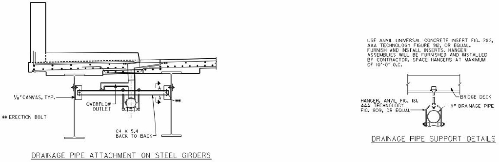
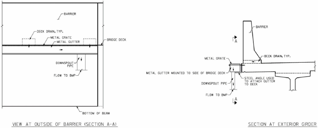
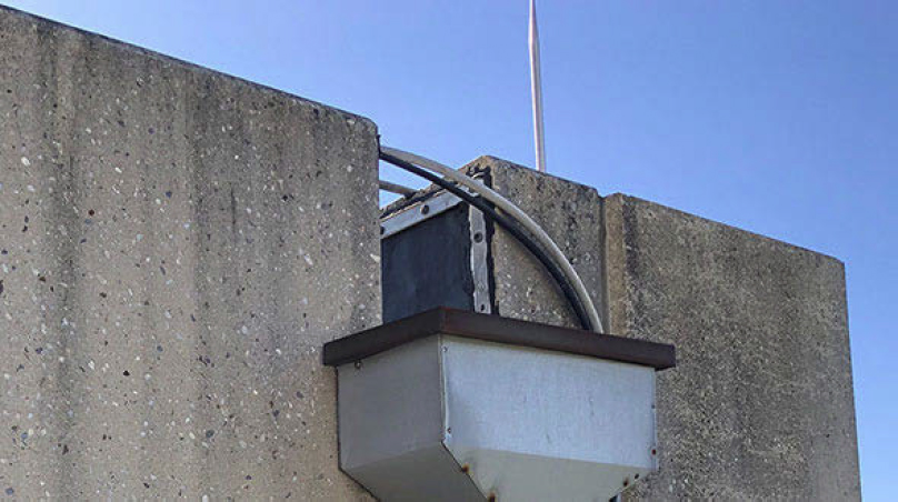
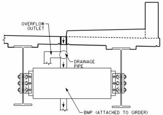
Figure 2 shows an example of an approach that could be used to mount a new conveyance system below a bridge deck. This example shows pipes mounted using metal struts, but a similar approach could be installed using concrete anchors or other fittings. Figure 3 shows an example of an open channel or gutter used with continuous or intermittent openings in the side barrier. Figure 4 shows an example of a drain box that could be affixed to the outside of the bridge to collect water from intermittent openings in the side barrier.
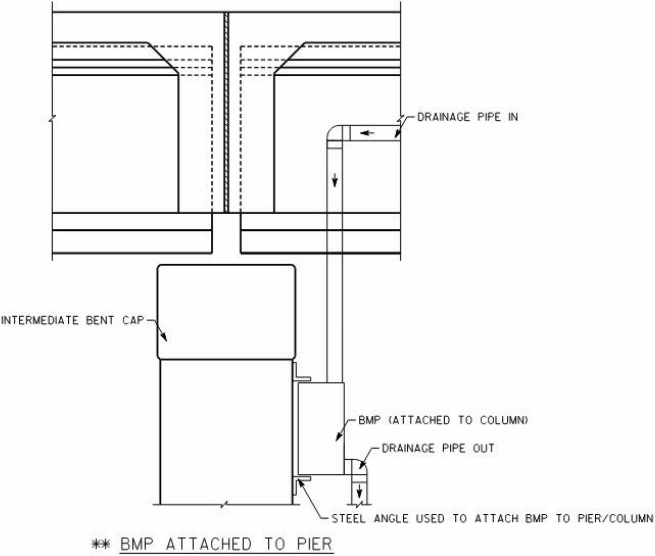
Figure 5 shows examples of closed pipe conveyance systems routing flows to a local bridge bent. Figure 6 shows examples of a larger closed pipe conveyance system routing flows across multiple bridge bents to a more centralized location. In these examples, flow is routed to the bridge abutment, but a similar configuration could route flow to a single intermediate bent for treatment. Figure 7 shows an example of a piped system sized for only the water quality flowrate with overflow pipes for larger flowrates. Figure 8 shows an example of an open channel system used to collect and convey water from deck drains.
In summary, some of the drainage conditions found in bridges are more challenging to retrofit than others. Each of these options requires a large number of fittings and conveyance elements and the design must be supported by hydraulic and structural calculations. Some alternatives may require unusual fittings. In general, the options that allow atmospheric separation between the existing conveyance and the new conveyance (i.e., pipes free falling into trough or gutter options) require the lowest burden of proof relative to drainage capacity as these have no potential to reduce the capacity of the existing system. However, gutters are an uncommon design feature in bridges and may be considered a non-standard design element.
Source: Atlanta Commercial Roofing Contractors

Source: Wisconsin DOT (https://wisconsindot.gov/dtsdManuals/strct/inspection/insp-fm-pt2ch7.pdf)
Source: Florida DOT (:https://fdotwww.blob.core.windows.net/sitefinity/docs/default-source/maintenance/str/bi/reference-manual/chapter-10-deck-drainage.pdf?sfvrsn=f4f8a4d7_0)

Source: Young Shin Engineering and Construction (http://www.goys21.com/eng/s2/s2_3_2.php)

Source: Young Shin Engineering and Construction (http://www.goys21.com/eng/s2/s2_3_2.php)

Source: Young Shin Engineering and Construction (http://www.goys21.com/eng/s2/s2_3_2.php)
Relative Structural Risks
Each bridge is a unique structure. Absent a detailed analysis of a given bridge, it is not possible to categorically determine feasibility or infeasibility relative to structural issues. Additionally, the structural risk posed by BMP retrofit can depend on the size and weight of the BMP and its location, therefore the question of structural risk may differ for a smaller, more distributed suite of BMPs compared to a larger centralized BMP. As a result, any design process needs to be based on project-specific structural loading calculations, seismic analyses, and risk analyses. As part of calculations, the mass of the BMP should be calculated assuming it is loaded with sand throughout its full headspace and fully saturated.
Notwithstanding the above, some generalization can be useful to support assessment of potential opportunities. For the purpose of preliminary design development, we classified three potential locations and provided initial commentary on their relative structural risks. This is intended to support initial screening of potential options. The authors of this memorandum, while civil engineers, are not licensed structural engineers and are not performing structural analysis services.
Substructure - Bents or Piers: The substructure including the bents or piers is typically designed to carry the largest load. Installation on the bents should avoid the major concern of compromising the bridge structural integrity with the added dead load of a BMP. The weight of the BMP would normally be a very small percentage of the total design load of bents. Depending on the bridge length and the number of BMPs required, multiple bents may need to be used. Mounting a BMP to an existing bent can be accomplished using various techniques of drilling, adhesive anchors, bolts, rods, bracing and straps. Figure 9 illustrates one example mounting option.
Superstructure - Beams: The bridge beams (including girders and cross beams) are also designed to carry a large load; however, each individual beam carries a lesser load than bents or piers. The most likely circumstance would be to mount between the bridge beams to allow distribution of the load between the two elements (see example in Figure 10). However, drilling into prestressed concrete beams is not advisable, so a beam retrofit mounting location is not recommended for bridges of this construction.
Edge Barrier - Railing or Parapet: Edge barriers are a possible location for a retrofit BMP, depending on the type and structural capacity. These elements typically have the smallest design load, and installation of a BMP would have the greatest potential structural impact. In general, an edge barrier constructed of concrete is more likely to be able to carry the additional load from a retrofit BMP. The BMP could be mounted in a cantilevered orientation outside the bridge or under-mounted below the bridge deck (Figure 11 and Figure 12). The cantilevered option generates a greater overturning moment on the edge barrier and may pose somewhat greater structural risk for some edge barrier types.
Overall, each of these options may potentially provide adequate structure bearing capacity. However, a case-by-case analysis is needed to confirm this.


Access for Construction and O&M
O&M factors are critical in determining potentially feasible locations of BMP location within the bridge environment. Every BMP requires periodic inspection to ensure its water quality performance and hydraulic capacity is within design, which has associated costs and personnel demands. The inspection frequency depends on the BMP design and likely clogging rate based on pollutant loading which could vary by design and pollutant loading. As discussed above, maintenance needs for BMPs are substantially different than current bridge maintenance paradigms. Substantial quantities of loose media or media modules (of some sort) will need to be removed in some way and replaced in a manner that sustains original capacity and treatment performance.
In general, designs should target annual maintenance intervals to coincide with annual bridge inspection and maintenance, similar to typical schedules for maintaining drainage of high priority bridges of DOTs interviewed. However, this may not be possible for bridges with very constrained BMP footprints and/or high sediment loading. Regardless, maintenance intervals for small footprint media filtration BMPs are likely to be relatively frequent, so it is essential that the BMP be located where it can be safely and efficiently inspected and maintained. We expect that maintenance of media filter BMPs would require additional equipment and a longer work period than needed for inspection and drainage system maintenance. However, synchronizing these efforts would help reduce the number of mobilizations and road closures.
The primary O&M factors to consider when determining potential locations of an on-bridge BMP are listed below and then discussed is the following subsections:
- Maintenance access
- Personnel safety
- Availability and capabilities of specialized equipment
- Cold climate O&M needs
Maintenance Access
Accessibility of on-bridge BMPs influence the cost, level of effort, and equipment required for routine BMP inspection and maintenance. Acknowledging that DOT maintenance budgets are limited, it is understood that access should be designed for maximum efficiency to minimize the time needed for staff to conduct the tasks. Similarly, access should minimize the need for purchase of specialized equipment and/or the duration of time needed for rental equipment. Yet, installation locations for on-bridge BMPs are limited and may not be able to be conveniently accessible.
For BMPs installed on bents typical access may be accomplished from the bridge roadway using specialized under-bridge inspection equipment (see additional detail below) or through installation of a custom catwalk. The catwalk would increase capital costs for construction but could reduce the annual maintenance costs and ease of access. Mounting methods should account for appropriate clearances for accessibility, which may not be impossible if mounted between bridge beams.
For BMPs installed between beams, there are very limited practical options for maintenance assuming the standard configuration where maintenance must occur from the top of the BMP. In very deep beams, it is possible there could be enough headroom for maintenance via under-bridge inspection equipment or a catwalk. However typical beam dimensions are similar to that needed for media filtration, so in many cases there would not be enough space between the top of the BMP and the bridge deck to perform maintenance. If a BMP is designed to extend below the beams, this would improve maintenance access.
BMPs installed on the edge barrier may also require specialized access similar to bent and beam installations if mounted under the deck. However, if an edge barrier BMP is cantilever mounted, inspection and maintenance can likely be accomplished from the bridge roadway using a vacuum truck and/or hoist, providing the most accessible option. In any of these scenarios it is assumed that a lane of traffic would be blocked while conducting the maintenance. One possible exception is if the catwalk system is accessible in a manner that does not require lane closure. This may be more feasible to design in new bridge construction than retrofits.
Personnel Safety
As with any work on a bridge, personnel and traffic safety must be preserved while conducting BMP inspection and maintenance tasks. At a minimum, all O&M activities needs to comply with OSHA and State regulations. There are some unique characteristics for each of the BMP installation locations that would require appropriate planning, training, and equipment to provide safe maintenance access. Primary safety considerations include traffic control, fall protection, materials handling, and training. A site-specific job risk assessment should be conducted for any on-bridge BMP to fully develop a safety program.
Traffic control including lane closures on bridges is a routine DOT procedure and does not present unique challenge.
Fall hazards associated with accessing BMP locations pose the highest risk. For any O&M operations taking place under the bridge deck, a fall protection program is necessary. Specific considerations are needed for use of a lift truck and catwalk. Fall hazards can be minimized for operations using a vacuum truck or hoist to conduct maintenance from the bridge deck.
The O&M tasks will include lifting materials, such as removal and replacement of the filtration media in the BMP. While other inspection and maintenance programs (e.g., painting, anti-corrosion sealers) requires movement of materials, there is not a clear analog to filtration media in current bridge maintenance programs. The site-specific activities should be evaluated to determine if personnel can safely lift the materials manually or if equipment is needed, since the BMP design may affect these operations. Once the material is removed from the BMP, it must safely be transported for disposal. Carrying bags of media on a ladder would pose unique safety issues and challenges.
Task-specific training is required no matter which BMP installation location is implemented. Personnel conducting the O&M must be trained in safe operation of the equipment, fall hazards avoidance, traffic safety set-up and control, and methods for material handling.
Availability and Capabilities of Specialized Equipment
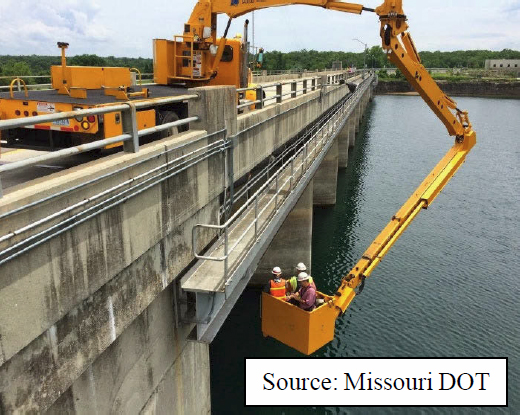
In considering potential BMP locations, designers should review the specialized equipment that is owned by the DOT or is available to rent. In many cases, there may be suitable equipment that is used for structural or coating inspections (see example below). Designers should determine the capabilities of the specialized equipment relative to its reach and weight limits and assess the potential BMP locations based on these parameters. Designers should also assess crew capabilities to safely operate the equipment.
Under-bridge boom or bucket truck.
Figure 13 shows an example of a boom or bucket truck designed for under bridge inspection and maintenance. The arm length, reach, and weight limits will vary by model. Media removed from the BMP may need to be lifted onto the lift truck platform manually, but the disposal will be made simpler with the aid of the equipment to raise it back to the bridge deck surface. Replacing the BMP media can be conducted using these steps in reverse order. These lifts are typically designed with protective guardrail systems on the working platform. Additional fall protection is also warranted, such as
a harness or other personal fall arrest system. Personnel must be trained and competent in the safe operation of the selected equipment.
Under-bridge platform trucks.
Figure 14 shows an example of mobile truck-mounted platform system that is designed for under bridge inspection and maintenance. This is similar to above but provides a temporary catwalk and ladder system. The dimensions and weight limits will vary by model.
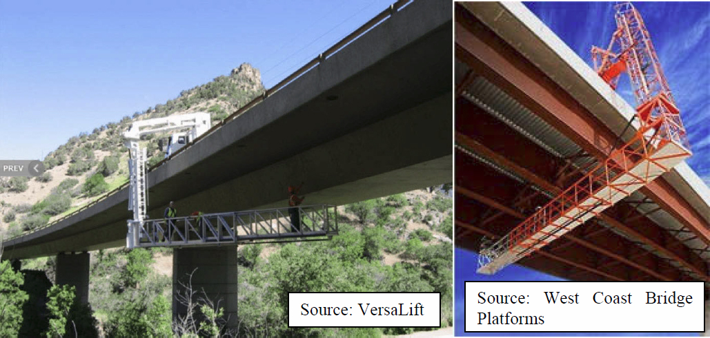
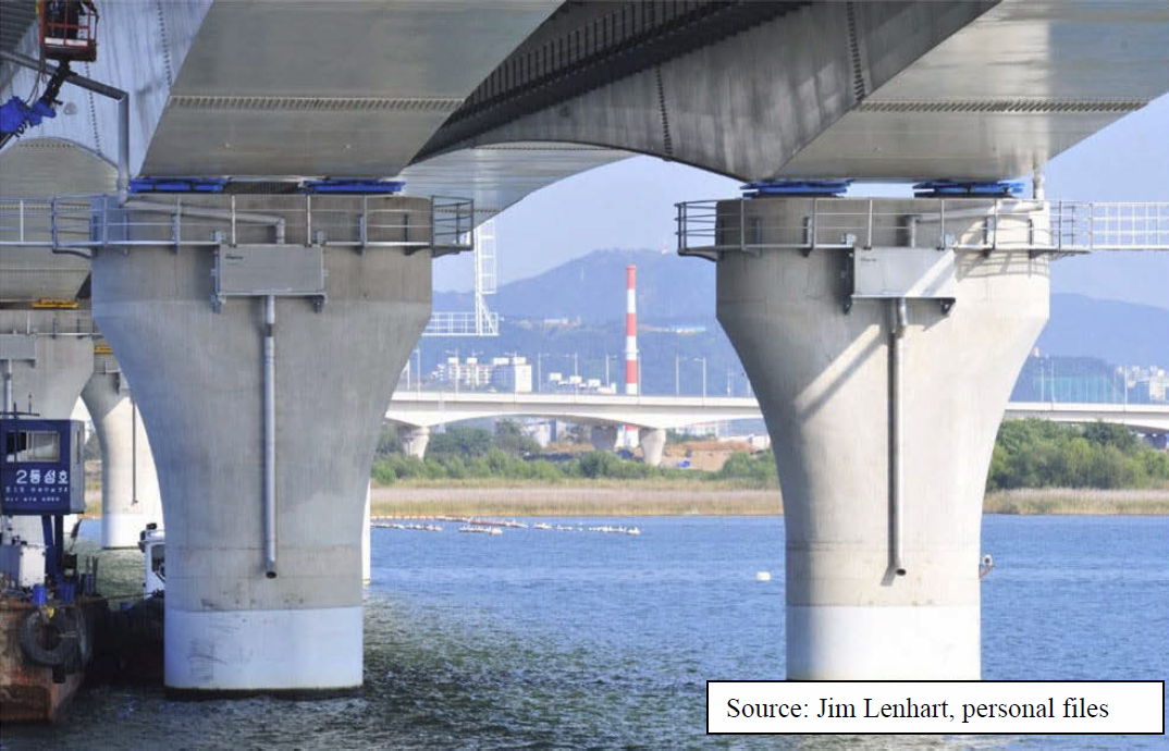
Permanent catwalk system.
Figure 15 shows an example of a catwalk system. This type of system typically includes an integral guardrail system as the primary fall protection. If O&M tasks require reaching outside the guardrail, personal fall arrest equipment may also be needed. The catwalk should be designed and constructed to carry the load of personnel anticipated for the tasks as well as the working weight of the BMP maintenance materials. A further consideration is the ongoing inspection and maintenance of the catwalk itself to ensure its structural integrity to provide a safe working environment. This example shows access from a watercraft. A plan for safe personnel movement from the watercraft to the catwalk is needed.
Whether access is from the bridge deck or from a watercraft, there is a need to determine the capabilities of equipment or hand labor to transport new media to the BMP and spent media away from the BMP for disposal. The distance from each access point to the BMP should be considered since the spent media will be saturated, adding to the weight of the materials.
Vacuum Truck and/or Hoist.
A vacuum truck and/or hoist could be operated from the bridge roadway, presenting the lowest safety risks. The vacuum or hoist could be used to remove the spent media from the BMP and the hoist could be used to install replacement media. The hoist might also be able to reach a catwalk to deliver and recover media. Still appropriate planning and precautions should be taken to minimize hazards. Any activities involving reaching over the bridge’s edge barrier will require fall protection.
Constructability
The complexity and feasibility of initial BMP construction is also a key factor that can influence the feasibility of BMP locations. Constructability is influenced by many of the same factors as discussed above for O&M, including the accessibility of the BMP location, the specialized equipment needed, the ability to protect worker safety. There are two main differences between initial constructability and long-term O&M.
- For construction of the system, the weight and size of components that need to be lifted would typically be much greater than for O&M. This likely requires different equipment, such as a larger lift truck or a barge instead of a smaller watercraft. A similar assessment of equipment availability and capabilities is needed to assess constructability.
- Construction will normally require more time than O&M. If this is performed from the bridge surface, this would require extended lane closures. If it is performed from the water, it would require an extended barge deployment to provide a stable construction platform. The relative cost and complexity of extended lane closure versus barge construction will need to be evaluated by designers on a case-by-case basis. In either case, this type of retrofit on an existing bridge will have a major cost and/or service impacts. Extended lane closures might provide opportunities for other kinds of inspections and/or maintenance (such as sand blasting/painting, etc.).
Tier 1+2: Assessment of Potential BMP Locations
This section integrates the Tier 1 and 2 design factors to assess potential BMP locations within the bridge environment in cases where it is not feasible to route water to land. The potential installation locations for on-bridge BMPs (and conveyance) include:
- Substructure (piers or bents),
- Superstructure (beams or girders), and
- Edge barrier.
The sections below present an integrated discussion of relative risks and opportunities for each potential location.
Bridges are each primarily unique structures, and the following generalizations must be confirmed on a case-by-case basis by an appropriate engineering analysis before implementation of a BMP retrofit. Aesthetic/architectural (and sometimes historical) considerations may also be evaluated if the mounting locations can be commonly observed by the general public.
BMP Placement on Substructure-- Bents or Piers
Structural risks.
Mounting the BMP to bents or piers presents the lowest structural risk as the elements have the greatest load bearing capacity relative to potential BMP weights. BMP installation on a bent requires stormwater to be piped from deck drains in the intended catchment area of the BMP, as discussed in the “Conveyance System” section above. The added load due to the pipe size and water weight should be evaluated for structural implications, including an assumption that the BMP is filled entirely with sand and is fully saturated.
Floodway and other clearance risks.
The flood elevation may be a critical parameter in determining the feasibility of this option. If the only viable option for BMP placement on a bent is below the base flood elevation, then the cost of assessing and mitigating floodway impacts posed by the BMP and protecting the BMP from flood-related damage is likely to be a major design consideration and could be a fatal flaw. Clearance for navigation is unlikely to be a major issue related to attachment at bents or piers as shipping channels typically include setbacks from these features.
Conveyance feasibility and complexity.
Conveyance to bents is likely to be reasonably feasible in most cases but may be more complex or challenging depending on the number of drains, the type of drain, the ability to extend pipes below the bottom of the beams, and any obstructions such as crossbeams that would interfere with pipe routing. This option may require larger pipes than a more distributed BMP but may allow BMPs to be more centralized to reduce O&M needs.
O&M feasibility and complexity.
Mounting BMPs on bents or piers may result in fewer BMPs to treat a given bridge, simplifying maintenance compared to more distributed BMPs. However, BMPs installed on a bent will require specialized access for inspection and maintenance. For example, a catwalk system
may be constructed that can be accessed from the roadway or a boat. In certain circumstances, it may be possible to reach the BMP on the bent with a specialized lift truck designed for bridge inspection and maintenance while parked on the bridge deck. The latter option should be strongly prioritized due to the high cost and complexity of boat-based maintenance. Additionally, access via a catwalk and ladders may be acceptable if present, however systems or approaches would be needed to transport media.
Constructability.
Constructing a retrofit BMP on a bent will require access from below the superstructure. The most likely scenario is to use a barge as a platform for construction over water. In certain instances, it may be possible to access the retrofit site from a specialized lift truck depending on the necessary reach and available equipment. The designer will need to assess the relative costs and impacts of an extended lane closure versus a barge deployment. One option is to try and time the install to coincide with heavy maintenance of the bridge itself to limit lane closure impacts.
Overall assessment.
Mounting on bents or piers is potentially feasible for many bridges. The ability to have safe and cost-effective maintenance access is critical to the viability of this option. If the only access is via watercraft, this would pose a severe cost burden as maintenance (including some amount of media replacement) are anticipated approximately an annual maintenance interval, which is substantially more often than other major maintenance activities such as painting or corrosion work. Additionally, the potential for floodway impacts could be a fatal flaw for this option if the only viable bent or pier locations are below the floodway elevation.
BMP Placement on Superstructure-- Beams
Structural risks.
The most likely circumstance from a structural perspective would be to mount between the bridge beams to allow distribution of the load between the two elements. The ability to attached new mounting equipment to beams may be simpler for metal beams than concrete, however either may be feasible with structural design review and appropriate installations. The capacity to tolerate new deadload on the beams (from BMPs and conveyance features) is a critical factor affecting the viability of this option and cannot be confirmed without structural design review.
Floodway and clearance risks.
If there is limited clearance, this may require the BMP to be tucked between the beams. This could create severe difficulties for construction and O&M as discussed below.
Conveyance feasibility and complexity.
Bridge deck drains are typically located on the outside edge of the bridge beams. Therefore, to route water to a BMP, the BMP would need to hang at an elevation below the beam to allow piping to carry stormwater into the BMP, unless the piping is routed through the beam. However, it should be noted that DOTs typically avoid having any utilities installed lower than the beams. Floodway and other clearance risks could also prevent this. Similar to other installation locations, piping will be required to be mounted to the superstructure. Piping through the beam would need to be structurally evaluated if that option is pursued.
O&M feasibility and complexity.
Inspection and maintenance could be very difficult for BMPs installed between beams. The BMP would need to be installed low enough so the beams and deck do not block access. In any case, the beams would pose a major obstruction for maintenance activities, such as media replacement. Potential methods to gain access to an installation between beams is use of under-bridge inspection equipment. These methods would require case-by-case basis to verify feasibility, but based on our professional opinion, this unlikely to be viable. In general, if floodway and clearance issues require the BMP to be tucked between the beams, this is likely a fatal flaw for reasonable constructability and maintenance access in most cases. If the BMP can be extended below the beams, then this is potentially more viable.
Constructability.
Construction of a BMP between beams will require access from below the superstructure. The most likely scenario is to use a barge as a platform for construction over water. Or a lift where they could be accessed via land.
Overall assessment.
This option is believed to have limited feasibility. It may only be feasible in cases where (1) conditions and policies allow the BMP to be suspended below the lower strand of the beams, and (2) access is possible via a specialized equipment from the bridge deck.
BMP Placement on Edge Barrier-- Railing or Parapet
Structural risks.
A bridge railing or parapet is a possible location for a retrofit BMP, depending on the type and structural capacity. The BMP could be mounted in a cantilevered orientation outside the bridge or under-mounted below the bridge deck (Figure 11 and Figure 12). The added load due to the pipe size and water weight should be evaluated for structural implications. A site-specific analysis should also be performed to determine whether a BMP would affect the crashworthiness of the barrier.
Floodway and clearance risks.
This option would have limited floodway and clearance risks in most cases.
Conveyance feasibility and complexity.
This BMP location is primarily feasible if the drainage from the bridge is outside of the outermost girder. If the deck drains are inside of the outermost beam, then it would not typically be feasible to route water to a BMP located outside of the beam, unless the BMP is located below the lower strand of the beam or if the beam can be penetrated to allow conveyance. However, in our review of example bridges, drainage is often outside of the outer beam and would support this placement.
O&M feasibility and complexity.
Installation of a BMP on an edge barrier in the cantilevered orientation provides the simplest access for inspection and maintenance of the options identified. If the BMP is installed in a cantilever mounting, it is likely that inspection and maintenance could be accomplished from the bridge roadway using a vacuum truck and/or hoist. If tucked under the bridge deck, this could pose much of the same complexity as the mounting location between beams; however, it could be somewhat more accessible as one side of the BMP would be exposed to allow removal and replacement of media.
Constructability.
Construction of a BMP on an edge barrier can likely be conducted from the roadway deck but will likely require use of a specialized lift truck, hoist, or crane (depending on load limits) to complete the retrofit. Barge-based construction may be needed if traffic impacts must be avoided.
Overall assessment.
This option, particularly the cantilevered configuration, is superior to others for accessibility and constructability and would normally be feasible for conveyance. However, the structural risk to the edge barrier is a key potential fatal flaw for this option. Given the variability in edge barrier types, a site-specific structural design assessment would be needed for each bridge to determine if this option is viable. If the as-is condition of the barrier is not suitable, then options to locally strengthen or reinforce the barrier may need to be considered. Bracing from the outer bridge beam may also be considered.
Table 4 summarizes the most important pros and cons of each location and potential factors that could render the option infeasible.
Table 4. Comparison of pros/cons for BMP implementation by installation location.
| Location | Pros | Cons | Potential Fatal Flaws |
|---|---|---|---|
| Bents |
|
|
|
| Beams |
|
|
|
| Location | Pros | Cons | Potential Fatal Flaws |
|---|---|---|---|
| Edge Barriers |
|
|
|
Tier 3: Supporting Design Factors
The design factors in this section are critical to support an effective and maintainable BMP. These are identified and discussed briefly. Additional guidelines on these design factors will be provided in subsequent project phases as appropriate.
BMP Geometry and Flow Configuration
In our experience, the most common and practical option is a box filled with media in a vertical flow configuration. The design should allow access to the media surface for maintenance. The underdrain system should hold the media and prevent washout while maintaining permeability. Details of this configuration can vary depending on site-specific design goals.
Variations on this approach could better support O&M. As discussed below in “O&M Procedures” the ability to replace media efficiently is a key design consideration in the bridge environment. This consideration is integral with the details of BMP geometry. For example, the ability to access from the side and/or remove media as modular units would potentially improve viability. Further effort is needed to develop potential detailed design options.
There are also a variety of vendors that offer space-efficient treatment options with a similar set of design parameters and performance goals. The design process to develop space-efficient BMPs with efficient O&M needs has been a focus of private-sector companies for decades. Therefore, one potential design approach is to provide the space and structure necessary to mount one of these technologies, design the conveyance system to this location, and rely on one of these proven technologies to provide treatment.
Treatment Media
Treatment media is discussed in the Task 1a memorandum. There are relatively proven alternatives for treatment media, including custom specifications and proprietary vendor products. However, these types of medias require careful QA/QC to operate at these design rates. Especially since they will be blended to remove solids borne and dissolved metals. The ability to procure treatment media and periodically replace treatment media with materials of consistent quality are critical to development of BMP designs and implementation.
Pre-treatment Options
As illustrated in the “BMP Sizing” section, the clogging lifespan is a key factor that may affect the viability of on-bridge treatment. However, in normal conditions, the particulate matter that leads to clogging is relatively fine and unlikely to be effectively removed in a pre-treatment system that would fit within the space available on a bridge. Pre-treatment may be most viable and necessary in cases with higher grit loading and/or trash loading. A pre-settling chamber could help reduce the amount of grit and trash accumulating on the media bed surface but would substantially increase BMP weights.
BMP and Conveyance Construction Materials
Traditional on-land BMPs often involve concrete boxes. This is nearly universal among compact media filtration BMPs supplied by vendors and is also common in custom designs. However, this adds weight to the design and may not be needed or desirable for on-bridge applications. Designs should consider plastic, fiberglass, or metal construction of media filter boxes to reduce weight.
An example retrofit performed by Multnomah County (OR) included custom metal boxes fabricated by the supplier containing a Stormwater Management StormFilter cartridge, designed to fit within the specific space and slope of the bridge (personal communication, James Lenhart).
Additionally, pipe components should be assessed for their structural integrity and weight. Metal pipe provides better structural integrity and requires fewer supports but has a greater weight than plastic pipe. However, metal piping can corrode and therefore my require more maintenance (painting/coating).
O&M Procedures
Maintenance intervals for typical on-bridge BMPs need to be better understood. However, regardless of this uncertainty, it is known that maintenance intervals will be relatively frequent (likely around annual). Therefore, specific O&M procedures need to be established as part of the design phase to support efficient O&M. Access is the most important factor and is discussed above.
In addition to access, the design needs to consider how media and other components will be replaced. Normal maintenance for vendor supplied compact media filtration products involves surface scraping at an annual interval and full-depth media replacement at multi-year intervals. This approach and frequency could be viable in the bridge environment, however, hand labor to scrape and manage loose media may be prohibitive due to the time required. A vacuum truck could possibly be used to remove the surface of the media. Replacing loose media in this environment could also be a challenge.
In the bridge environment, the cost of mobilization and traffic control may be much greater than the cost of media. So, it may make sense to shift toward full media replacement at each interval. Designs could also include replaceable pre-filled media modules (porous bags, modular trays, other structures) that can be lifted out and replaced quickly, then rehabilitated at a maintenance facility. This option would require clear access above or possibly the side of the BMP. The only on-bridge treatment examples the research team is aware of included Stormwater Management StormFilter cartridges or similar systems, which support a modular replacement paradigm.
Any option involving replaceable modules (cartridges, trays, bags) would need to consider the potential for short-circuit bypass of water around the perimeter of these systems. This could be accomplished via outlet control, where a restriction on the underdrain discharge controls the flow through the system.
Further effort is needed to detail potential design options and O&M procedures.
Cold Climate O&M Needs
Winter conditions in colder climates result in another factor that particularly affects O&M of an on-bridge BMP. Freezing temperatures should also be accounted for in the BMP design. Water retained in an on-bridge BMP will freeze more readily than typical BMPs installed in the ground since the earth acts as insulation and warming in some cases. Design accommodations should be made in an on-bridge BMP to allow for the expansion of water turning to ice within the BMP structure as well as blockages that could occur in the outlet. Cold climate impacts affect all on-bridge BMP locations and types under consideration. Any BMP design needs to be evaluated as to how it will be operated and maintained in cold weather.
Various other cold weather factors are present on bridges regardless of BMPs, including snow accumulations around the deck drains, inadequate drainage during melt periods, and snowplow operations. As long as BMPs do not interfere with drainage, these issues are unlikely to be exacerbated by BMPs.
4. Design Case Studies and Alternatives Evaluation
Starting Assumptions
Three BMP retrofit design case studies were developed from bridge design plans provided by Georgia DOT (GDOT) and Minnesota DOT (MnDOT). These bridges are only a small subsample of bridge types and conditions. We have used these to help illustrate various options of on-bridge BMP implementation and design considerations. Each case study illustrates characteristics of on-bridge BMP implementation, including:
- BMP mounting methods and location
- Conveyance methods
- Number of BMPs
- Size of BMPs
- Installation and O&M considerations
A variety of basic assumptions were used as a starting point for the design.
For the purpose of these case studies, we imposed the starting assumption that it was infeasible, impractical, or too costly to route flows for treatment to on-land BMPs, at the abutment or below the bridge.
The team assumed no new or enlarged penetrations were allowed in the bridge deck, based on research and feedback from DOT interviews. Stormwater would need to be collected using existing bridge drainage and retrofitting as needed for conveyance to the BMPs. Conveyance piping capacity was sized to carry the water quality flow without increasing gutter spread on the roadway. Conveyance would be designed with overflow routes for higher flows, and to avoid potential issues with clogging. The details of conveyance systems are not fully illustrated.
The BMP to be implemented is assumed to be a rectangular box with an inlet pipe, pre-treatment layer, treatment media layer, underdrain layer, outlet pipe, and an overflow outlet described above. This step in the evaluation does not focus on the BMP design details related to water quality but instead focuses on the implementation requirements described above, such as structural considerations, installation location and conveyance requirements. The BMP was sized as described in the “Design Requirements” section. Via the conveyance system configuration or a supplemental overflow pathway, the BMP would not result in roadway flooding when the media becomes clogged.
Each case study presents a potential option for BMP implementation for the particular bridge characteristics to minimize the risks related to the major criteria described in the “Design Requirements” section. The case studies provide discussion on each of these criteria as well as figures and calculations to illustrate the selected BMP installation location and conveyance details.
Because the BMP is a conceptual unit, engineering judgement was used to determine the structural capacity of the bridge elements that would support the BMP installation locations and methods. Specific structural engineering calculations were not conducted.
Case Study 1—GDOT State Route 3 over Peachtree Creek
Background
This GDOT two-span bridge has a total bridge length of 220’-4” and bridge gutter to gutter width of 42’-6”. The bridge is on a normal crown and the bridge superstructure is steel plate girders. The existing bridge drainage system consist of 4-inch diameter deck drains spaced at 4’-6” on each side of the bridge in the gutter. Each of the existing 88 deck drains are cored holes with 4-inch PVC couplers and extensions that freely discharge below. Refer to Exhibit 1 for design drawings of the existing bridge with markups to illustrate the BMP retrofit. An aerial photograph is shown in Figure 16.

Drainage Areas
To develop the conceptual BMP retrofit for this case study, the BMP installation locations were selected for mounting on the bents. A practical drainage area for routing flows to a BMP is approximately 0.1 acres or less, equivalent to 4,300 square feet (sq. ft.). To achieve this, the bridge was divided into four drainage areas. The highest point of the bridge profile divided the bridge into two areas along the length of the bridge and the crown of the bridge bisected those two areas for a total of four drainage areas (Table 5).
Note that in this case, the only logical routing was to the end bents. However, this was used as an illustration of how a BMP could be located on central bents as well if it was a longer bridge.
BMP Sizing
Table 5 below indicates the square feet of tributary area and the corresponding BMP box footprint for each area based on 80% design capture of the stormwater. The BMP box is assumed to be 30 inches deep and 30 inches wide. The associated length of the box to achieve the water quality capture for each area was determined, ranging from 5-feet to 18-feet long.
Table 5. Drainage areas and BMP sizing for Case Study 1.
| Drainage Area ID | Drainage Area | BMP Footprint for 80% Capture | BMP Length, assuming 30"x30" box (width x depth) |
|---|---|---|---|
| sq. ft. | sq. ft. | ft. | |
| Area 1 | 3,952 | 46 | 18 |
| Area 2 | 3,536 | 41 | 16 |
| Area 3 | 1,276 | 15 | 6 |
| Area 4 | 1,142 | 13 | 5 |
BMP Installation Location
The conceptual BMPs are proposed to be mounted to the front side of the bridge abutment bent and below the beams at each of the four corners of the bridge. Given the short length of the bridge, these locations are actually at the end of the bridge. But this example also illustrates how water could be routed to a mid-span bent. Steel angles that run the entire length of the BMP box are proposed for mounting the BMP, using dowels into the cast-in-place concrete bent.
Floodway Clearance
The 100-year flood elevation is around 3 feet below the lower chord of the bridge. There are no other known clearance requirements. This provides marginally adequate vertical space to install a BMP on bents while remaining above the base flood elevation, but only allows about 0.5 feet of clearance from the lower chord to the BMP top and around 2 feet to the underside of the deck. This may interfere with O&M activities. A designer may choose to evaluate whether a lower elevation could be tolerable for floodway impacts to improve access. The proposed design shown in Exhibit 1 shows the about 2 feet of the BMP mounted below the base flood elevation, which would require additional analysis for potential impacts to the floodway and shear stresses to the proposed BMP installation.
Conveyance Approach
The stormwater is proposed to be routed to the BMPs via 4-inch pipes connected to the existing deck drain extensions. Piping will be mounted to the steel girders with typical pipe hangar assemblies. The pipe is sized to convey the water quality flow from the 6-month, 24-hour design storm (QBMP), which in Georgia is based on a 3-inch rainfall event. Overflow vents are proposed to allow flows exceeding the water quality flow to drain freely to maintain the original hydraulic design capacity (QTOTAL), which in Georgia is based on a 5.03-inch rainfall event. This strategy reduces the pipe size needed and minimizes the cost and weight impacts of a larger pipe. The BMP is also fitted with an overflow structure for higher flows or if clogging occurs. Note that, for smaller drainage areas like Drainage Areas 3 and 4, the water quality design flow may not hydraulically require a 4-inch pipe, but pipes smaller than 4-inches are not recommended on bridges due to maintenance issues with clogging due to trash, sediment, and debris.
O&M Access
If this BMP needed to be installed on central bents rather than abutments, then O&M access would be challenging. It is likely that an under-bridge boom truck would be required, with lane closure for the
duration of maintenance. The headspace for O&M (about 1.5 feet) could pose added challenges for removing loose media or media modules.
Conclusion
This case study demonstrates an option for installing BMPs on the bridge bents. The lack of accessibility to conduct routine O&M tasks presents an ongoing challenge which suggest that these circumstances would more easily host a BMP retrofit installed on land by the bridge abutment with stormwater flow conveyed through piping. This example was specifically intended to illustrate on-bridge treatment. However, this bridge would be more suitable for an on-land BMP.
Case Study 2— GDOT County Road 130 over White Oak Creek
Background
This GDOT three-span bridge has a total bridge length of 264’-0” and bridge gutter to gutter width of 30’-0”. The bridge is on a normal crown and the bridge superstructure is prestressed concrete beams. The existing bridge drainage system consists of 4-inch diameter deck drains spaced at 10’ on each side of the bridge. Each of the existing 50 deck drains are formed holes in the deck without pipe extensions. The drains have a drip bead formed around the bottom that allow free discharge below. Refer to Exhibit 2 for design drawings of the existing bridge with markups to illustrate the BMP retrofit. An aerial photograph is shown in Figure 17.
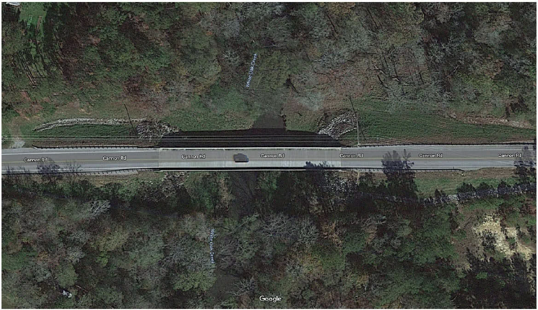
Drainage Areas
To develop the conceptual BMP retrofit for this case study, the BMP installation locations were selected for mounting on the edge barriers. A practical drainage area for routing flows to a BMP is approximately 0.1 acres or less, equivalent to 4,300 sq. ft.. In this case, a smaller drainage area was selected to minimize the length of the BMPs so that it could be attached to the barrier with less difficulties, so the bridge was divided into six drainage areas. The highest point of the bridge profile divided the bridge into two areas along the length of the bridge and the crown of the bridge divided into three areas for a total of six drainage areas (Table 6).
BMP Sizing
Table 6 indicates the square feet of tributary area and the corresponding BMP box footprint for each area based on 80% design capture of the stormwater. The BMP box is assumed to be 30 inches deep and 30 inches wide. The associated length of the box to achieve the water quality capture for each area was determined to be 6-feet long.
Table 6. Drainage areas and BMP sizing for Case Study 2.
| Drainage Area ID | Drainage Area | BMP Footprint for 80% Capture | BMP Length, assuming 30"x30" box (width x depth) |
|---|---|---|---|
| sq. ft. | sq. ft. | ft. | |
| Area 1 | 1,320 | 15 | 6 |
| Area 2 | 1,320 | 15 | 6 |
| Area 3 | 1,320 | 15 | 6 |
| Area 4 | 1,320 | 15 | 6 |
| Area 5 | 1,320 | 15 | 6 |
| Area 6 | 1,320 | 15 | 6 |
BMP Installation Location
The conceptual BMPs are proposed to be mounted to the concrete edge barrier. Three BMPs are required on each side of the bridge, for a total of six BMPs, each the same dimension of 6-feet long. The attachment detail consists of the BMP resting on a steel frame assembly bolted to the barrier. This bridge is a typical robust structure with prestressed concrete supporting a cast-in-place concrete deck and barrier. Once cured the barrier, deck, and beam act compositely to carry structural loads and allow for the additional weight of the BMPs on the edge barrier. Holes can be drilled into the barrier to provide bolted connection of the steel frame assembly. It is recommended that a designer evaluate this mounting design for maintaining the crash resistance of the edge barrier.
Floodway Clearance
The 100-year flood elevation is around 1 foot below the lower chord of the bridge and about 5 feet below the elevation of the deck. There are no other known clearance requirements. This allows enough room between the deck and the floodway for a 30-inch-deep BMP but requires the BMP to be installed at the same elevation range as the beams to avoid floodway impacts. This influenced the decision to mount the BMPs to the edge barrier rather than to bents or piers.
Conveyance Approach
The stormwater is proposed to be routed to the BMPs via 4-inch pipes connected to the existing deck drains. Piping extensions will be fitted to the existing flush underside of the deck drains using a 4-inch gasketed flange mounted with masonry anchors. Piping will be mounted to pipe hangar assemblies mounted near the bottom of the edge barrier. The pipe is sized to convey the water quality flow from the 6-month, 24-hour design storm (QBMP), which in Georgia is based on a 3-inch rainfall event. Overflow vents are proposed to allow flows exceeding the water quality flow to drain freely to maintain the original hydraulic design capacity (QTOTAL), which in Georgia is based on a 5.03-inch rainfall event. This strategy reduces the pipe size needed and minimizes the cost and weight impacts of a larger pipe. The BMP is also fitted with an overflow structure for higher flows or if clogging occurs. An open channel option could also be considered for this to avoid the need to connect to the flush underside of each deck drain.
O&M Access
The location of the BMP overhanging on the side of the bridge may require some specialized equipment to install. A cantilever option is preferred to simplify maintenance which can likely be accomplished from the bridge roadway using a vacuum truck and/or hoist. Appropriate safety precautions should be taken as discussed in Section 3- “Tier 2 Primary Design Factors.”
Conclusion
This case study demonstrates an option for installing BMPs on the bridge edge barrier. The bridge design of cast-in-place concrete deck and barrier provides a suitable structural mounting location, but it should be noted that other edge barrier types, such as railings, may not be as competent for supporting the structural loads of BMP mounting without reinforcement. This mounting location provides better accessibility for routine O&M tasks than locations mounted to the bridge substructure or superstructure. The number of BMPs required for this case study is higher per square foot of treated area to reduce the size of each BMP and allow for edge barrier mounting.
Case Study 3—MnDOT Interstate 90 over Mississippi River
Background
This MnDOT two-unit bridge has a total bridge length of 2,593 feet and bridge gutter to gutter width of 50 feet for each unit. The bridge superstructure is unique for each unit— Unit 1 is prestressed concrete haunched box beam and Unit 2 is prestressed concrete I beams. The existing bridge drainage consists of 14 steel deck drains cast in the deck in the gutter with 8-inch pipe extensions below connected to a 16-inch mainline pipe. The mainline pipe is attached to the bridge with threaded rod hangars and is routed past the end bents to discharge stormwater on land at the bridge abutment. Refer to Exhibit 7 for design drawings of the existing bridge with markups to illustrate the BMP retrofit.
Clearly, the best option for this bridge would be to position a BMP on the land. However, for the purpose of this case study we have assumed that the piping system did not exist prior to retrofit and an on-bridge option is required. This is an artificial assumption for the purpose of illustrating design approaches.
Figure 18 shows an example view of this bridge.
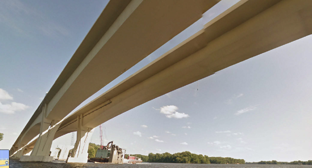
Source: Google Street View
Drainage Areas
In this case, a variety of drainage areas were selected to make use of the existing deck drains, dividing the bridge into 14 drainage areas (Table 7). A BMP is proposed at each drain location.
BMP Sizing
Table 7 below indicates the square feet of tributary area and the corresponding BMP box footprint for each area based on 80% design capture of the stormwater. The BMP box is assumed to be 30 inches deep and 30 inches wide. The associated length of the box to achieve the water quality capture for each area was determined, ranging from 5-feet to 44-feet long.
Table 7. Drainage areas and BMP sizing for Case Study 3.
| Drainage Area ID | Drainage Area | BMP Footprint for 80% Capture | BMP Length, assuming 30"x30" box (width x depth) |
|---|---|---|---|
| sq. ft. | sq. ft. | ft. | |
| Area 1 | 2,625 | 29 | 12 |
| Area 2 | 4,614 | 51 | 21 |
| Area 3 | 1,160 | 13 | 5 |
| Area 4 | 1,505 | 17 | 7 |
| Area 5 | 6,846 | 76 | 31 |
| Area 6 | 5,432 | 61 | 24 |
| Area 7 | 2,749 | 31 | 12 |
| Area 8 | 2,919 | 33 | 13 |
| Drainage Area ID | Drainage Area | BMP Footprint for 80% Capture | BMP Length, assuming 30"x30" box (width x depth) |
|---|---|---|---|
| sq. ft. | sq. ft. | ft. | |
| Area 9 | 1,178 | 13 | 5 |
| Area 10 | 9,753 | 109 | 44 |
| Area 11 | 3,636 | 41 | 16 |
| Area 12 | 7,444 | 83 | 33 |
| Area 13 | 7,444 | 83 | 33 |
| Area 14 | 6,840 | 76 | 31 |
BMP Installation Location
The conceptual BMPs are proposed to be mounted to edge barrier. While this bridge already had a pipe to land and associated supports, this case study assumes that these elements did not exist and provides an example attachment detail for a retrofit BMP on a bridge of this type. An alternative location would be to mount the BMPs to the bridge bents, which is structurally preferable, but the O&M is much more challenging than the edge barrier mounting.
Floodway and Other Clearance
We were not able to obtain information about the necessary clearance requirements for this bridge. However, we were able to design the BMP installation higher than the lower chord which is likely to meet any clearance constraints.
Conveyance Approach
The location of the BMPs at each of the deck drains will eliminate the need for conveyance pipes. The extension pipes discharge to the BMP and provide the ability for overflow for higher flows or if clogging occurs.
O&M Access
The location of the BMP overhanging on the side of the bridge may require some specialized equipment to install. A cantilever option is preferred to simplify maintenance which can likely be accomplished from the bridge roadway using a vacuum truck and/or hoist. Appropriate safety precautions should be taken as discussed in Section 3- “Tier 2 Primary Design Factors.”
Conclusion
This case study demonstrates an option for installing BMPs on the edge barrier. BMPs are proposed as retrofits at each existing deck drain, although this results in a variety of drainage areas and associated BMP sizes, some of which are quite large for mounting to the bridge. If pursued for implementation, a flow splitter could be evaluated to reduce the size of the larger BMPs.
As discussed above, the actual design of this bridge had piping to the abutment, and therefore on-bridge treatment is not needed and is not preferred. However, this illustrates an alternative design paradigm that could have been used for a bridge of this type.
5. Synthesis, Recommendations, and Research Needs
Synthesis of Findings
Bridge Characterization and Overall System Design
Bridges are unique structures. While there are some commonalities in bridges, the differences that exist are very important for the design, construction, and operation of retrofitted BMPs. In the sections above, we have identified and evaluated key design considerations and approaches for how to determine feasibility and an overall BMP design. This reinforces the need for project-specific engineering and alternatives analysis to meet the various objectives.
This memo identifies baseline assumptions and primary factors that need to be carefully evaluated to determine where BMPs can be located and how the overall conveyance and treatment system can be designed, constructed, and maintained. The most important factors to guide the overall design and feasibility assessment include (1) structural capacity, (2) ability to capture and convey flow, (3) ability to avoid floodway or other clearance impacts, (4) ability to construct the BMP, (5) ability to provide safe and affordable O&M access, and other considerations.
Designers will benefit from guidelines about how to integrate these factors and examples of design approaches and associated cost estimates. However. we believe there is very little opportunity to have standard off-the-shelf system designs that cover the wide range of locations, conveyance requirements, connection details, and other factors that pertain to the design process for an on-bridge BMP retrofit. This means that nearly every BMP project will be a unique design process that requires contributions from multiple departments and disciplines.
BMP Design
When considering all the aspects that go into retrofitting a bridge with BMPs, the questions of what is “inside the box” and how it is configured are minor factors. This research project will explore more details of BMP configurations to optimize treatment and O&M procedures. However, we have started the process with a focus on the larger issues that affect BMP placement and operation. Through this broader design process, we have developed a better understand of the requirements for the BMP itself in order to be feasible and practical in on-bridge retrofit applications:
- Systems located within inlets themselves are unlikely to be feasible in DOT bridges, except in rare circumstances.
- A rectangular box with vertical media flow provides adequate flexibility to fit in most cases. While other shapes and flow configurations could be considered, the benefit of these options does not appear to justify the challenges posed by more complex geometries and potential intellectual property issues associated with alternative flow configuration.
- In order to balance weight and space constraints with treatment goals, BMP dimensions will need to be highly customizable to the dimensions available in the bridge environment and the sizing needs for a wide range of drainage areas. Vendor products such as the Contech Stomrwater Management StormFilter®, Contect Filterra®, and BioClean Modular Wetland® provide insight into what designers will likely need. For example, each of these products offers 10 to 20 sizing options. Additionally, structural connection points of the box will need to be customizable in order to maximize flexibility.
- An alternative material to concrete (plastic or metal) would be preferrable for the box, as this will reduce the weight and potentially support more flexible mounting options.
- Clogging interval is likely to be the most important factor in lifecycle costs. Therefore, designs that reduce clogging risk and allow simpler remediation of clogging will be preferred. However, there are relatively limited techniques to reduce clogging risk within the space available in the bridge environment. The most promising approach is to use media with high initial permeability media (with hydraulic restriction on the outlet) such that the design flow can be maintained for a longer period.
- Modular media components that support simpler and more efficient field maintenance activities are likely to be critical to managing maintenance costs and time requirements for lane closures, even if such systems require more materials and more complex design. However, the design and fabrication of these would be more complex and costly than simpler options.
- In order to meet treatment and hydraulic needs, media needs to be subject to careful quality control. Since this will be a regular maintenance event rather than only a capital project, DOTs need to confirm that there will be ongoing access to suitable and consistent media needs that can be procured by O&M crews.
- Existing vendor BMP products have demonstrated treatment performance, quality-controlled supply chain, defined O&M requirements, and space efficiency. In cases that a BMP of some sort is feasible in the bridge setting, these products appear to be reasonably similar in size to our non-proprietary sizing assumptions. Adaptation of these designs to utilize a lighter box to reduce unnecessary weight may be more certain and cost-effective for DOTs than developing custom BMP designs and media specifications.
As part of the Phase I Interim Report, we will further outline BMP design approach and potential research activities for Phase II address prioritized data gaps.
Recommendations and Research Needs
Overall, our work reinforces the findings of NCHRP Report 778, specifically that on-land BMP placement is far preferrable than on-bridge placement. Any on-bridge option is likely to involve a highly custom designs, especially for conveyance and mounting/access of the BMPs that requires extensive effort to analyze various constraints and configure bespoke design elements. However, through this initial design assessment, we have developed a systematic way of approaching design questions and a prioritization of design considerations. We can utilize this to help organize potential needs for guidelines and research.
Factors Requiring Project-Specific Evaluation
The following topics will require project-specific analysis by designers. Designers would potentially benefit from general guidelines, expanded examples, and references, however there is very limited ability to develop standardized design guidelines or templates that adequately address all of these factors.
- Structural capacity
- Structural attachment details
- Floodway and other clearance considerations
- Overall retrofit approach for existing drainage system
- Access and equipment options for construction and O&M
Potential Guidelines and Examples to Support Project-Specific Decision Making
For the following topics, new research may be valuable to develop standard design guidelines and prepare design examples that can have some general utility for designers:
- Template specifications for media mixtures to target pollutants of concern within small footprints (See Memo 1a)
- Validation of expected treatment performed by recommended media mixtures
- Improved estimates of clogging intervals to help predict maintenance needs, including guidelines on effectiveness of pre-treatment approaches and effects of deicing grit on BMPs
- Template design details and specifications for BMP components, including bridge-specific design approaches to support efficient O&M procedures including, low weight designs and modular designs that could be replaced in their entirety for maintenance (and rehabbed for use again)
- Template design details for conveyance elements
- Guidelines for estimating lifecycle cost of BMPs
We will use this list of potential needs to develop options for a Phase II research plan as part of the Interim Report.
6. References
Granato, G. E., and Cazenas, P.A. (2009). Highway-Runoff Database (HRDB Version 1.0)—A data warehouse and preprocessor for the stochastic empirical loading and dilution model. Washington, D.C.:U.S. Department of Transportation, Federal Highway Administration, FHWA-HEP-09-004, 57 pp. http://webdmamrl.er.usgs.gov/g1/FHWA/SELDM.htm.
Smith, K. P., and Granato, G. E. (2010). Quality of Stormwater Runoff Discharged from Massachusetts Highways, 2005–07. U.S. Geological Survey Scientific Investigations Report 2009–5269, 198 pp. http://pubs.usgs.gov/sir/2009/5269/.
Qian, Q., Liu, X., Charbeneau, R., and Barrett, M., 2013, Hydraulic Performance of Small Scale Bridge Deck Drains, Center for Transportation Research, Technical Report 0-6653-1, http://library.ctr.utexas.edu/ctr-publications/0-6653-1.pdf


