On-Bridge Stormwater Treatment Practices: A Guide (2024)
Chapter: 2 Characterization of the Bridge Environment for Stormwater Treatment

CHAPTER 2
Characterization of the Bridge Environment for Stormwater Treatment
Chapter at a Glance
The purpose of this chapter is to guide a reader in answering the following questions:
- What are the defining characteristics of the physical environment that this Guide covers?
- What design objectives are relevant for the bridge environment in general and for specific projects?
- What aspects of a bridge have the greatest influence on the stormwater treatment design process? How should existing conditions be characterized? What influence do these factors have on design development and feasibility?
This chapter establishes a baseline upon which the remainder of this Guide is based. These factors drive many of the site-specific decisions needed to determine whether on-bridge stormwater treatment is feasible and, if so, the overall stormwater treatment design.
What Is the Bridge Environment?
The statutory definition of a highway bridge, used by the FHWA, is:
A structure including supports erected over a depression or an obstruction, such as water, highway, or railway, and having a track or passageway for carrying traffic or other moving loads, and having an opening measured along the center of the roadway of more than 20 feet between under copings of abutments or spring lines of arches, or extreme ends of openings for multiple boxes; it includes multiple pipes, where the clear distance between openings is less than half of the smaller contiguous opening. (23 CFR §650.305)
According to the FHWA’s InfoBridge website (https://infobridge.fhwa.dot.gov/Data), there are more than 600,000 bridges in the United States, with more than 140,000 of these being part of the National Highway System. This Guide is primarily focused on bridges that have on-bridge drainage infrastructure, such that it may be relevant to place a BMP somewhere within the span of the bridge.
All bridges serve similar purposes and share common design objectives. However, the existing inventory of the nation’s bridges spans more than a century of design evolution, and each must be uniquely adapted to many site-specific factors. Therefore, there are both commonalities and differences within this environment.
Some of the most consistent commonalities in the bridge environment identified in this research project include:
- Most parts of a bridge serve a structural purpose and are an integral part of the original structural design. There are relatively limited parts of a bridge that can be modified without potentially impacting structural performance.
- Space is nearly always constrained in the bridge environment. The types, shapes, and sizes of space available for stormwater treatment differ greatly between bridges based on their unique designs.
- Drainage outfalls tend to be much smaller and more closely spaced than those implemented in typical highway designs. A penetration through a bridge deck or edge barrier for drainage inherently weakens the bridge, so these are typically kept to smaller features that are more tightly spaced.
- Bridges face various vertical constraints related to base flood elevation and other clearance requirements. Many bridges are designed based on providing minimum vertical clearance above these constraining elevations.
- O&M for existing bridge drainage infrastructure is currently a high burden for DOTs and requires disproportionate effort relative to other highway O&M due to the need to work in a constrained environment and to the relatively small diameters of the drainage systems, which make them prone to clogging.
- DOTs are experienced in performing stormwater drainage system O&M in the bridge environment. However, existing maintenance regimes are less intensive and require different equipment and different personnel training than would be needed to inspect and maintain on-bridge BMPs.
Beyond these commonalities, there are a wide range of conditions across bridges in the United States. The design of bridges has evolved over the years, and many considerations influence site-specific designs (e.g., abutment types, earthquake standards, length, height, architectural choices). These factors contribute to a large number of combinations of conditions encountered in the bridge environment that may influence the feasibility, placement, design, and O&M of stormwater treatment elements. This Guide describes a systematic approach for characterizing the specific combinations of conditions that exist for a given bridge and integrating these findings to support design.
Design Objectives and Feasibility Thresholds for On-Bridge Stormwater Treatment
Design objectives for on-bridge stormwater treatment have commonalities with stormwater treatment of other highway segments but also differ in important ways that narrow the suite of potential stormwater treatment design options. Additionally, project-specific factors pertaining to the bridge, receiving water, and DOT policy and guidance can influence the design objectives for a specific bridge.
The purpose of this section is to guide the project team in articulating the design objectives for the project. Defining objectives prior to starting the design process can help reduce the degree of freedom in making subsequent decisions and provide transparency in why decisions were made. Some design objectives represent potential fatal flaws if minimum thresholds cannot be met. These feasibility thresholds should be defined in this process. Note: If the design team is already aware of a likely fatal flaw, the potentially fatal flaw issue should be investigated first. Other objectives would be irrelevant if a fatal flaw cannot be overcome. The section titled “Screening of Potential Fatal Flaws” at the end of this chapter provides additional guidelines.
Organization of this Section
The following sections identify key categories of design objectives. For each category of objectives in this section, the Guide introduces what the objective covers, articulates a template objective that can be used as a starting point, and identifies ways in which these could be adapted to specific projects.
Water Quality Treatment
This objective pertains to the level of treatment provided for highway runoff, specifically the pollutant removal performance (i.e., the reduction in pollutant concentration and load for the water treated). This will influence the treatment technology and design parameters needed to provide this treatment.
Template objective: Treatment objectives are typically described by state or local statutes or regulation. In absence of a specific local objective, the Washington Department of Ecology’s Technology Assessment Protocol—Ecology (TAPE) program is recognized as a benchmark for the effective treatment of stormwater in compliance with Municipal Separate Storm Sewer System (MS4) Permits and related standards in the United States. This program establishes performance standards for BMPs that could be adapted to set project-specific objectives.
For highway pollutants, TAPE standards for enhanced (metals) treatment and phosphorus treatment are most applicable. A summary of relevant TAPE standards is presented in Table 1.
Basis for project-specific adaptation: Project-specific design goals could be developed based on various factors, including:
- DOT-specific BMP selection guidance compatible with applicable regulations and local conditions.
- Receiving water pollutants of concern.
- Specific pollutant discharge limitations for a given receiving water, such as driven by TMDLs.
Additionally, iterative feedback from the design process may indicate that, given the constraints for a particular bridge, it is not possible to fully meet these standards. This could mean that a lower level of treatment can be targeted consistent with a maximized level of control.
Sizing and Long-Term Fraction of Water Treated
This objective pertains to the sizing of BMPs and the portion of runoff or peak flow rate of runoff that is targeted for treatment by the project. This influences how much water is treated. In combination with the treatment performance (discussed in the previous section), this determines the overall reduction in pollutant load achieved.
Template objective: DOT drainage design manuals typically specify the water quality sizing criteria specific to the project location. This can be expressed as design storm depth or design storm intensity converted to a design volume or flow rate. It can also be expressed as a fraction of long-term runoff volume that must be treated. Local standards should be used as the default objective. Chapter 4 of this Guide includes guidelines on how to configure on-bridge BMPs to meet local water quality treatment sizing standards.
Table 1. TAPE standards for Basic, Enhanced, and Phosphorus treatment.
| Pollutant | Units | Influent Range | Removal Standard | TAPE Standard |
|---|---|---|---|---|
| Total suspended solids | mg/L | 20-100 | Effluent < 20 | Basic |
| 100-200 | ≥80% removal | |||
| Dissolved copper | μg/L | 5-20 | ≥30% removal | Enhanced* |
| Dissolved zinc | μg/L | 20-300 | ≥60% removal | Enhanced* |
| Total phosphorus | mg/L | 0.1 to 0.5 | >50% removal | Phosphorus* |
*Enhanced and Phosphorus standards require that Basic treatment also be achieved.
If water body-specific requirements are driving the need for on-bridge treatment, these requirements may also specify a sizing standard different from the DOT standard sizing approach and should be the default objective.
Basis for project-specific adaptation: In the case of stormwater retrofits in constrained environments, a flexible sizing approach could be used to target maximized treatment while balancing this with O&M needs and project constraints. Chapter 4 of this Guide includes guidelines on sizing on-bridge BMPs to balance long-term performance, size, weight, and required O&M frequency.
Portion of Bridge Treated
This objective pertains to how much of the bridge is targeted to be treated and whether it is permissible to leave some areas untreated.
Template objective: As a starting point, designs should attempt to capture and treat the full area that drains through on-bridge drainage infrastructure. Designs should minimize the area of the bridge that must be treated by BMPs located on the bridge itself by routing water to land where possible. Portions of the bridge that drain into the ground-level sections of the adjacent highway would have additional treatment options that are more consistent with conventional stormwater management guidance.
Basis for project-specific adaptation: Based on a cursory review of the bridge, there may be sections where collection and treatment are clearly impractical. For example, an area of the bridge where water drains directly through grated sections will be nearly impossible to capture and likely should be removed from the design objectives early in the design process. The portions of the bridge that can be reasonably captured and treated should be informed on an iterative basis through subsequent project planning and design steps.
Lateral Spread
This objective pertains to bridge drainage and traffic safety as it relates to how far into the travel lanes water spreads during design drainage conditions. This will influence whether drainage modifications are acceptable.
Template objective: Stormwater retrofits should not cause an unacceptable increase in lateral spread when analyzed for the applicable local drainage design event, typically a 10- to 25-year return interval event. Modifications to drainage should not result in less drainage capacity from the bridge or increased risk of drainage system clogging between normal drainage system maintenance events. This normally means that there can be no consolidation of inlets, which would result in a greater flow of water on the bridge deck between less frequent inlets.
Basis for project-specific adaptation: If, as part of the characterization of the existing conditions, the design team determines that increases in the lateral spread are acceptable (e.g., there is currently surplus separation from the travel lanes), then the design team may set an alternative objective that limits but does not prohibit lateral spread. This can influence whether a change in drainage configuration, such as a consolidation of inlets, can be considered. If a sag section exists on a bridge, design criteria may be more stringent.
Structural Risk
This objective pertains to increases in the likelihood or severity of structural failure resulting from a retrofit of the bridge with a stormwater treatment system. It is important to define thresholds of acceptability to help guide the design and determine if this is a fatal flaw.
Template objective: In general, any addition of weight to a bridge should be identified as an increase in structural risk and appropriately assessed. Bridge-specific structural analysis is required to determine if the additional weight is within the available structural capacity of the bridge and if the incremental risk is acceptable.
Basis for project-specific adaptation: DOT bridge design manuals provide additional guidance to assess structural risk. If a structural analysis is conducted as part of existing condition characterization, this could support the development of project-specific objectives such as specific weight limits, specific parts of the bridge that are not viable, or other limits to help guide potential solutions.
O&M and Worker Safety
This objective pertains to the ability to perform required O&M and meet applicable worker safety requirements for O&M activities. Setting this objective serves as a key threshold that needs to be met for a design to be feasible.
Template objective: Designs should minimize O&M needs to balance them with other constraints and objectives. A target O&M frequency of yearly or longer is desirable. It should be possible for O&M activities to be performed by non-specialized O&M crews with conventional maintenance equipment while meeting safety requirements. Retrofitting a bridge with BMPs must not increase the O&M needs or reduce the level of service of drainage features and thereby increase lateral spread risk. The addition of stormwater treatment system elements should not unreasonably interfere with other bridge O&M activities.
Basis for project-specific adaptation: The tradeoffs between BMP capital cost, weight, and O&M needs are a critical aspect of the on-bridge BMP design process. Guidance for exploring these issues is provided in Chapter 4 of this Guide. While worker safety should never be compromised, an increase in O&M frequency may be considered if it reduces BMP weight or otherwise improves other factors of the design. Iterative feedback from the design process may justify the adaptation of this objective, within reason.
Traffic Impacts from Construction and Ongoing O&M
This objective pertains to the traffic impacts that would occur from the construction of the on-bridge stormwater treatment system and the activities needed to provide ongoing O&M.
Template objective: In general, unreasonable impacts on traffic should be avoided for both the construction and O&M phases, including driver safety, congestion, and emergency services such as police, ambulance, and fire.
Basis for project-specific adaptation: Thresholds for acceptable impacts will vary by bridge. Project-specific objectives are important to define at the outset of a project and use to guide the ranges of acceptable traffic impacts during both the construction phase and for ongoing O&M activities. These should consider existing traffic patterns, levels of congestion, criticality of the route, and other factors.
Procurement and Replacement of Components
This objective pertains to the purchasing of components for initial construction and replacement as part of O&M or rehabilitation. The design needs to be informed by any specific objectives or constraints that exist for procurement.
Template objective: Public agency procurement processes normally prefer goods and services that can be provided by multiple suppliers. It is also desirable to have known supply options to provide replacement parts to avoid special procurement during the O&M phase.
Basis for project-specific adaptation: DOT-specific procurement rules should be consulted to define project-specific or agency-specific objectives. This may include a discussion of how many commercially available products need to be available within a given product category to enable the specification and sourcing of proprietary technologies. This should cover both initial procurement and ongoing procurement for O&M.
Cold Climate Risks
This objective pertains to specific design or O&M-related issues that need to be considered in cold climates. Cold climate issues affect road operations (e.g., traction sand, deicer) and result in the freezing of water held in the BMP.
Template objective: In regions that experience frequent or extended freezing temperatures, the BMP design should not compromise drainage during freezing weather and should not be damaged by freeze-thaw action.
Basis for project-specific adaptation: Specific understanding of DOT- and bridge-specific cold weather operations obtained as part of existing condition assessment should influence design objectives.
Cost and Financial Feasibility
This objective pertains to the cost-effectiveness of a design and whether the design is financially feasible. Setting thresholds for cost and financial feasibility can be important to justify decisions about whether a design should proceed.
Template objective: Three default objectives pertain to cost and financial feasibility:
- Project alternatives should seek to minimize whole lifecycle costs.
- Projects should not exceed cost thresholds such that they are financially infeasible according to DOT policies and applicable regulatory drivers.
- Wherever an option exists that achieves equivalent or better water quality benefits for lower cost, this option should be used if at all possible.
Basis for project-specific adaptation: Standards for assessing financial feasibility depend on the type and details of the regulations or legal agreement that make on-bridge treatment necessary. For example, stormwater treatment obligations driven by Municipal Separate Storm Sewer System (MS4) permits are based on an underlying “Maximum Extent Practicable” standard, which is normally considered to include financial feasibility and proportionality between costs and benefits. State-specific standards, such as Washington State’s AKART standard—an acronym that means “all known, available, and reasonable methods of prevention, control, and treatment”—incorporate the concept of reasonableness. The inclusion of the “R” for “reasonableness” in AKART suggests there are some circumstances and some technologies that a regulator might consider unreasonable to require. Treatment requirements driven by TMDLs may have a different standard. Likewise, treatment requirements driven by the Endangered Species Act could be based on a “reasonable and prudent alternatives” standard.
Regulatory drivers typically do not define a certain cost per area treated or pollutant load removed as a threshold for financial feasibility. However, the establishment of thresholds may become a key factor in subsequent decisions. Therefore, at the outset of a project, design teams
can work to define such thresholds to support subsequent decisions. This could involve internal benchmarking (i.e., normal stormwater treatment costs), regulatory analysis, interaction with regulatory agencies, or other steps.
Prioritization of Objectives
After setting objectives, design teams should consider and document the relative priority of objectives and their categorical meaning to support future decisions. For example, some objectives may be fatal flaws if the minimum objectives cannot be met. Others may be factors that guide the design and serve as the basis for comparison between alternatives but are not likely to be fatal flaws. Having a prioritized list of objectives can help guide the assessment of existing bridge conditions and subsequent design development efforts by putting greater emphasis on higher-priority objectives.
Assessment of Existing Conditions Influencing Stormwater Treatment Design
A thorough assessment of existing conditions and design constraints is critical in any highway project. This is especially important in the bridge environment due to the many design objectives that need to be met (see the previous section, “Design Objectives and Feasibility Thresholds for On-Bridge Stormwater Treatment”) and the range of factors that can influence the feasibility and design of an on-bridge stormwater treatment. This section is intended to serve as a guide and checklist for assessing the existing conditions of a bridge. It provides guidance on assessment activities and key information needs. This section also summarizes the implications of bridge-specific conditions on design decisions.
Bridge Structural Characteristics
The structural design and structural condition of bridges vary immensely with different bridge ages, site-specific conditions, DOT design standards, and many other factors. Examples of some of the different structural characteristics relevant to on-bridge stormwater treatment designs are documented in the appendix and Web-Only Document 401. Any additional load to a bridge represents an increase in structural risk. Many bridges may not have been designed to current standards because of their age or may have suffered deterioration due to corrosion. Around 14 percent of bridges in the United States either have posted load limits or are classified as being in poor condition (FHWA 2023). Therefore, the structural condition of a bridge is an essential factor in on-bridge BMP design, and it is not possible to generalize using an average assumed condition.
Bridge elements have differing suitability for BMP retrofits based on their structural characteristics. Figure 2 illustrates some of the key structural elements of a bridge. Substructure elements, such as bridge bents or piers, are typically designed to carry large loads with safety factors, so the additional structural load of a BMP can be relatively small in comparison. The superstructure elements, such as girders or beams, are also typically designed for large loads where the weight of a BMP could be relatively small. However, each individual beam carries much less load than a typical bent or pier. Bridge edge barriers often carry a lower design load. Enlarging openings in the bridge deck could be viable but would typically require cutting through existing reinforcement, which would need to be carefully assessed.
Key aspects of the bridge structural design that may affect BMP retrofit options include:
- Structural design standards and policy. Structural design criteria have changed over time since bridges were built. While newer bridges may have adequate surplus load-carrying
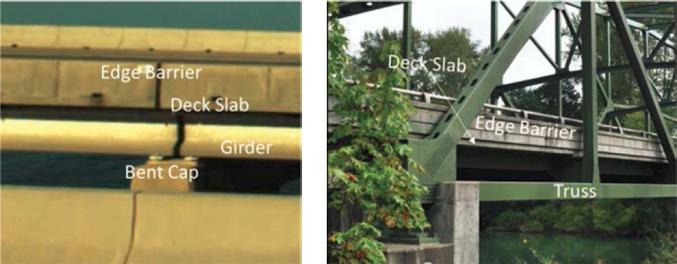
Figure 2. Key structural elements on various bridges.
- Pier or bent layout. The spacing and location of bridge piers or bents are key variables that differ greatly between bridges. They affect how much drainage area could potentially be routed to a BMP located at a pier or bent.
- Girder type and section. Bridge girders are commonly constructed of steel or reinforced concrete. The cross sections of these girders, the placement of girders, and the structural elements between girders vary by bridge. In some cases, a grid configuration of girders and cross beams may exist that limits the clear space between girders. Diagonal beam and girder arrays are also relatively common and result in irregularly shaped areas. Metal girders allow better options for attachment than concrete girders.
- Edge barriers. Edge barrier designs vary greatly, including solid barriers and a variety of open or partly open barriers. These are designed to resist impact from automobiles but may have a wide range of structural properties.
- Reinforcement details, particularly around inlets. These can influence whether openings can be enlarged.
capacity to accept the weight of a BMP, older bridges may already be deficient with respect to current structural design standards. It is possible that modifications to the structural elements of bridges would trigger the need to update the bridge to current structural design standards. DOTs may have various policies regarding structural modifications to existing bridges.
Key Assessment Activities and Information Needs
Each DOT should carefully consider and define the approach the design team will use to integrate structural considerations into the design development process. At a minimum, a bridge-specific structural analysis will be needed to determine the acceptability of a proposed design once BMP locations and sizes are determined. This analysis will need to consider the current condition and design loads on the bridge.
A full structural analysis requires substantial investigation. Therefore, it may be advantageous to take a phased approach to structural characterization. Early in the design process, a preliminary structural assessment could provide tentative guidance for identifying the parts of a bridge that could potentially support additional load and evaluating whether any modifications to them could be acceptable. This could guide the evaluation of candidate BMP placement options and sizing limits. Upon development of the preliminary design, a more detailed analysis could be performed to determine acceptability and/or refine the design.
If schedules allow, DOTs may prefer to perform a detailed structural analysis at the outset of a project before investing effort in other aspects of bridge characterization and preliminary design.
Implications for On-Bridge Stormwater Treatment Design
The structure of a bridge will highly influence the implementation of BMPs. Key decisions driven by structural considerations include:
- Is it possible to add or increase the size of bridge deck penetrations for BMP placement or added conveyance?
- Which parts of the bridge can support the mounting of conveyance elements and BMPs?
- How much weight can be added at distinct locations?
Existing Bridge Drainage System
Bridge drainage design criteria vary by state DOT and are influenced by regional precipitation patterns with the intent of preventing lateral spread that may impact the traveling public. Typical design drainage from a bridge deck is based on the peak flow from a 10-year to 25-year recurrence interval precipitation intensity. Regardless of specific criteria and calculation methods, the hydraulic requirement for bridge drainage is much larger than the design flow for water quality treatment, which is typically a smaller, more frequent design storm or intensity. Given that bridges were built at different times in history, it is possible that drainage design no longer meets the current drainage requirements of a DOT. It is considered essential that any modifications to bridges do not reduce the drainage capacity below the current drainage design criteria. It is possible that bridge modifications could potentially trigger upgrades to meet current drainage criteria.
Bridge drainage systems vary widely, as discussed further in this Guide. Drainage area sizes on bridges vary but are often very small, with tightly spaced drains to facilitate moving water quickly off the bridge deck to maintain safe roadway conditions. The smallest drainage area for individual drains in case studies was less than 100 square feet, but the research team found that drainage areas can range up to 10,000 square feet or more. The number of drains on a given bridge could number more than 10 for every 100 linear feet of curb, penetrating through the bridge deck vertically or through the edge barrier. For bridges that have open rails or tightly spaced drains, the discharge is effectively continuous along the length of the bridge.
Key Assessment Activities and Information Needs
The following activities are suggested to inform the on-bridge stormwater treatment design process:
- Review as-built drainage plans and perform a site visit to confirm existing conditions, if possible.
- Assess if any drainage features are deteriorated.
- Delineate drainage areas to existing drainage features.
- Determine drainage design flow rates and estimated lateral spread from original design reports or perform hydrologic and hydraulic modeling to estimate design flow rates and lateral spread based on as-built system attributes. This may not be needed if the proposed stormwater capture and conveyance system does not modify the existing drainage.
- Determine whether inadequate drainage or excessive maintenance have been identified as operational issues that should be addressed as part of a project.
Implications for On-Bridge Stormwater Treatment Design
Existing drainage patterns are one of the most important factors driving stormwater treatment design. This can influence the types of new features needed to capture and convey water to a treatment BMP, the potential locations and sizes of treatment BMPs, and other factors. Drainage configuration can be a fatal flaw if there are no reasonable ways to capture and convey water to
suitable BMP locations. Chapter 4 provides more detailed guidance on the assessment of drainage and implications for stormwater treatment design.
Existing Bridge O&M Activities, Potential BMP O&M Access Limits, and Worker Safety
Various features of a bridge require O&M and/or periodic inspections, including drainage, lighting, painting, structural inspections, and other elements or activities.
Bridge maintenance requirements and practices related to stormwater drainage and BMPs vary by state, region, and traffic volume. Variables that affect the O&M schedule include the potential for sediment, trash, debris, and deicing grit, which contribute to the clogging of deck drains and drainage pipes. The use of grit is common to help improve traction and the efficacy of pavement deicers, especially on bridges, which tend to be highly managed due to their propensity to have more severe icing issues than normal roadways. Sediment can be contributed by a variety of sources, including aerial deposition, construction, and traffic volumes—all factors subject to site-specific variability.
Drainage systems on bridges require substantial and sometimes unpredictable levels of O&M. DOT staff interviewed as part of this project stated that the level of effort to conduct regular O&M of current drainage systems put a strain on limited staffing and funding resources, forcing DOTs to develop a prioritization strategy. Typically, bridge drainage infrastructure is maintained annually for the highest-priority bridges, while lower-priority bridges are maintained at intervals of up to five years. DOT staff mentioned that the drains and pipes of some bridges often become clogged even with annual maintenance.
Sediment, trash, debris, and deicing grit accumulations will affect BMP performance and are a significant factor in on-bridge BMP implementation. DOTs in cold climates that apply large quantities of deicing grit seasonally noted that annual or more frequent maintenance is needed.
Overall, the existing maintenance programs to remove sediment and debris from drainage systems (at a 1- to 5-year interval) provide a reference point for the timing, equipment, and personnel needed to maintain an on-bridge BMP. However, based on interviews with DOT staff, this maintenance program is considerably different than what would be needed to maintain on-bridge BMPs. Crews do not typically need access below the bridge deck, do not operate boom trucks for under-bridge or over-edge work, are not typically removing bulk material for disposal or using drain jetting equipment to clear drains, and are not bringing material to the site to replace spent material. Given the substantial difference in time requirements, equipment requirements, and specialty supplies compared to what would be needed to maintain on-bridge BMPs, it appears clear that on-bridge BMPs would require a new or substantially modified maintenance program compared to the O&M programs that currently exist.
The National Bridge Inspection Program requires that inspections for structural conditions be performed every 24 months or more frequently. Lower-risk bridges may qualify for longer intervals. While inspection equipment can access most parts of a bridge, these inspections do not involve construction equipment necessary to maintain BMPs and would ordinarily be performed by personnel with different training than those tasked with O&M of the drainage systems.
Each DOT may have different capacities and policies for the types of maintenance that a bridge maintenance crew can perform, including worker safety, fall prevention systems, available on-bridge maintenance equipment, ability to use boats, and other factors. Early identification of capacity and limitations will be critical to guide BMP placement and overall stormwater treatment design.
Assessment Activities and Key Information Needs
Consultation with bridge O&M personnel and managers is suggested to inform the on-bridge stormwater treatment design process, including:
- Determine existing O&M activities, frequency, equipment needs, and lane closures required.
- Gain an understanding of typical O&M conditions observed for the bridge of interest (e.g., relative sediment, trash and debris loads, frequency of clogging, drainage issues).
- Determine whether there are any special provisions that may be needed for work over the edge of a bridge or over water.
- Inventory common equipment used in bridge maintenance or other similar O&M activities performed by the DOT that could potentially be used for O&M of on-bridge BMPs.
- Assess waterway navigability and existing DOT experience in using boats or barges for O&M activities, including associated limitations of this approach.
- Solicit input from O&M personnel on preferences for BMP placement.
- Solicit input from O&M personnel on preferences for stormwater capture and conveyance approaches.
Implications for Design
All BMPs require regular maintenance to operate. The proposed BMP types (described in Chapter 3) have a compact footprint to limit weight and are, therefore, expected to require substantial maintenance on approximately an annual basis. The ability to access BMPs safely and efficiently for O&M is a critical factor in sustaining performance. It is also a major part of the lifecycle cost of an on-bridge stormwater treatment system. Therefore, O&M access, personnel safety, and compatibility with existing DOT O&M capabilities are essential factors in developing on-bridge stormwater treatment designs and determining feasibility.
Cold Weather Operations and Issues
As discussed in the previous section, the use of deicer or traction grit on bridges may be higher than adjacent roads. Additionally, the use of traction grit may require special post-winter maintenance activities such as pipe flushing and grit recovery.
In addition, friable media elements such as granular activated carbon may break down more quickly in areas with frequent freeze/thaw cycles. The breakdown of friable media elements could require increased frequency of media replacement if friable elements degrade and clog media pores.
Assessment Activities and Key Information Needs
Consultation with bridge O&M personnel and managers is suggested to inform the on-bridge stormwater treatment design process, including:
- Gain an understanding of cold weather operations, including what type of deicer or traction material is used and the estimated quantities.
- Gain an understanding of post-winter O&M activities, including drainage system flushing and grit recovery.
Implications for Design
Cold weather operations could substantially increase the necessary cleanout frequency for on-bridge BMPs and associated conveyance systems, potentially requiring BMPs to use larger pre-treatment compartments. Additionally, flushing activities may require temporary modification of drainage systems to avoid discharge of flushed materials to on-bridge BMPs.
For BMPs in areas with frequent freeze/thaw cycles, it may be prudent to select a media with a lower percentage of friable media, such as granular activated carbon and biochar.
Traffic Impacts
DOT staff interviewed stated that lane closures are normally needed to maintain bridge drainage infrastructure, and therefore, DOTs are experienced in this. However, on high-traffic bridges, lane closures are done at night. Therefore, maintenance activities that require lane closures require appropriate safety provisions to be performed at night.
Assessment Activities and Key Information Needs
Various sources of information may support planning for construction and O&M activities to minimize traffic impacts:
- Current approach for lane closures during O&M activities, including frequency and duration.
- Existing congestion and safety concerns.
- Direct and indirect costs of lane closures (if available, could help inform design tradeoffs).
Implications for Design
For more critical routes with greater congestion, the need to limit the frequency of lane closures could be an important factor in BMP placement and O&M approach. This could justify larger BMP sizing to reduce O&M frequency (discussed in Chapter 4), maintenance by boat (where feasible), or other approaches.
High Water Elevation and Associated Clearance
A BMP placed within the bridge environment typically must not cause an impact on the base flood elevation unless approved as part of a floodplain modification process. For example, if a BMP is attached to a bridge in a location that extends below the flood elevation, this could reduce the hydraulic capacity under the bridge for conveying river flows, increase the upstream flood elevation, change scour patterns downstream of the bridge, and/or increase the risk of debris becoming stuck on the bridge. Additionally, this scenario could result in major damage to the BMP as a result of inundation and/or impact from debris. Construction of new bridge elements within the floodway would require a specific permitting process, including the potential for a flood map revision process. This consideration also applies to BMPs placed at the abutments or on land adjacent to a bridge below the flood elevation.
In coastal environments, high water levels can be influenced by high tides, waves, and storm surges and should account for projected sea level rise.
To maintain a gravity-based flow regime, BMPs will need to be located below the bridge deck. As many bridges are built with minimal clearance above high-water elevations to minimize cost, a BMP located beneath a bridge deck may fall below design flood elevation. Should a desirable BMP location be located below the flood elevation, the proponent would need to evaluate the flood impacts and O&M impacts of this alternative and pursue the necessary permitting.
Assessment Activities and Key Information Needs
Various sources of information may support design alternatives, including:
- Floodplain and floodway maps and elevations.
- Bridge-specific flood elevation studies, including project-specific hydraulic modeling performed as part of the original design process and/or performed to support the stormwater retrofit project.
- Potential for increases in floodplain elevations due to climate change, depending on DOT policies.
- Estimates of extreme water levels at tidally influenced sites, which can be found on the National Oceanic and Atmospheric Administration’s website at https://tidesandcurrents.noaa.gov/est/
- Sea level rise estimates, depending on DOT policies.
- Design wave heights, as applicable.
- Lake or reservoir water level monitoring records and operational rules for bridges crossing lakes or reservoirs.
Implications for Design
Determining maximum water elevations that apply will help determine the lowest elevations that BMPs can be placed while avoiding damage from high water and/or studies of flood impacts.
Navigation and Other Clearance
Other vertical clearance requirements may also apply to bridges in some cases, such as navigability (in over-water segments) or rail/traffic passage (in over-land segments). Some DOTs do not allow utilities to extend below the lower strand for reasons such as this. This may not apply to elements attached to a bent or pier where it would not interfere with navigability. Designers should determine and adhere to the DOT policy in this regard. This has similar implications as high-water clearance.
Architectural and Aesthetic Concerns
Some bridges have historic designations that prevent or require permits for certain types of modifications. Other bridges may have architectural or aesthetic significance, which may reduce the options for conveyance and BMP placement or may require more artistic elements that add costs.
Screening of Potential Fatal Flaws
A comparison of project objectives, feasibility thresholds, and existing conditions can support an initial screening of fatal flaws to determine if further design development should be proposed. Based on the research team’s review of case studies, the following conditions should be considered fatal flaws in most cases. Further guidance on these factors is included in Chapter 4.
Potential fatal flaw 1: BMPs need to be positioned underneath the bridge deck where there is no unobstructed vertical access to the BMP.
This condition occurs when BMPs need to be located between girders or attached to piers in such a way that the treatment BMPs are under the bridge deck. This condition would be especially constraining if the water body is not navigable.
Rationales: This condition will greatly complicate both construction and O&M. There are a variety of individual and interrelated factors:
- Construction by barge is very expensive and is limited only to slow-moving, navigable water bodies.
- Under-bridge access equipment is likely incapable of handling the loads required for construction.
- Under-bridge access equipment is likely incapable of handling the heavy loads of media materials required for O&M of BMPs.
- A vacuum truck with an extension could potentially reach these locations, but this also requires crews to access these locations to rake and direct the vacuum truck. This requires either a complicated ladder and catwalk system or the use of a boat for routine maintenance.
- Mobilizing an under-bridge inspection truck for twice-yearly inspections would be challenging.
- For many bridges, there is little clearance from high water to the underside of the bridge, either allowing no viable placement or providing limited clearance for O&M.
Individually, these factors could potentially be overcome, but collectively, issues associated with the placement of BMPs underneath the footprint of the bridge deck add costs, complexity, and safety risks for both construction and O&M.
Potential fatal flaw 2: Bridge deck drains are located between girders.
Rationale: The main issue is that this drainage configuration usually forces the BMP to be located below the bridge footprint since it will not be possible to extend pipes outside of the bridge footprint for access over the side of the bridge. This will result in the complications and extra costs described in the Rationale for “Potential fatal flaw 1.” Additionally, construction access for the construction of a new pipe system under the bridge deck would be challenging.
Potential fatal flaw 3: Edge barriers with a lower crash test-level rating and no option for BMP support from girders or piers.
This includes edge barriers with a crash test rating of less than test level-5 (TL-5), per Manual for Assessing Safety Hardware (MASH) criteria.
Rationale: In order to allow for the construction and maintenance of the BMP from the bridge, the BMP must be vertically unobstructed outside of the bridge footprint. The estimated weight for BMPs that treat about 0.05 to 0.1 acres of bridge deck is approximately 15,000 lbs. This would approximately double the design load of edge barriers with TL ratings of TL-4 (18,000 lbs vertical) and more than quadruple the design load for TL-3 and below (4,500 lbs vertical). Historic and irregular guardrails likely have TL ratings of less than TL-4. See additional discussion of MASH test level ratings in Chapter 5.
If the girders or piers are not of a material or location that can provide the primary support for the BMP, then the limited strength provided by TL-4 and smaller edge barriers would likely be a fatal flaw.
Potential fatal flaw 4: The bridge is classified as being in poor structural condition, is posted for load, or is nearing that rating level.
Rationale: Added weight of any sort would increase risk on a bridge that is already at risk. The estimated weight of candidate BMPs that treat between about 0.05 and 0.1 acres of bridge deck is approximately 15,000 lbs.
Potential fatal flaw 5: Unreasonable and unacceptable traffic interruptions during construction or O&M. Traffic interruptions would be unacceptable for conditions such as one- or two-lane bridges without adequate shoulders to serve critical routes for emergency services.
Rationale: In order to support over-bridge construction activities, the bridge would likely need to be closed for multiple months during construction, and would need to be closed every year or even more often during ongoing O&M. For longer bridges, O&M could require multiple weeks to complete for many units. Interruptions to traffic and particularly emergency services on critical routes could be a fatal flaw.
Potential fatal flaw 6: The bridge has a grated deck.
Rationale: Rain that falls on a grated deck passes directly through the bridge, preventing the conveyance of stormwater to the shoulder for capture and treatment.
In addition to the potentially fatal flaws noted earlier in this section, other factors have a major influence on the design complexity, cost, and impacts. The combination of multiple constraints could render a design infeasible. Chapter 4 provides guidelines for how to integrate the information obtained in bridge characterization to support decisions in cases where clear fatal flaws have not been identified.


