Leveraging Existing Traffic Signal Assets to Obtain Quality Traffic Counts: A Guide (2025)
Chapter: 2 Inductive Loop Detectors
CHAPTER 2. INDUCTIVE LOOP DETECTORS
INTRODUCTION
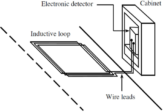
Inductive loop detectors were introduced in the early 1960s and have been one of the most widely used sensors for traffic management on freeways, arterials, and intersections. These sensors are used at signalized intersections for traffic detection and signal control. They can detect metallic objects including motorized traffic and bicycles. An inductive loop detector system (Figure 1) is installed in the roadway pavement and is comprised of three components: one or more turns of an insulated wire buried in the pavement (i.e., loop), an electronics unit housed in a controller or signal cabinet at the side of the road, and lead-in cables connecting the loops to the controller. When a vehicle or bicycle passes over or stops within the inductive loop, it generates eddy currents in the loop’s wire, causing a reduction in the loop’s inductance. This change in inductance triggers the electronics unit to activate its output relay or solid-state optically isolated output, which then sends a signal to the controller, indicating the vehicle’s passage or presence (Klein et al., 2006).
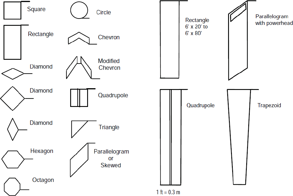
The loops can be connected in series or in parallel and can have different characteristics such as shape, dimensions, and configuration that vary based on the application and the accuracy of the required outputs. Figure 2 shows examples of short and long inductive loop shapes. Short loops are typically used for small-area point detection, whereas long loops are primarily used for large-area detection of vehicle presence. Given this design flexibility, loop detectors can detect a broad range of vehicles. Conventional 6-ft × 6-ft square loops that are typically found on 12-ft lanes are one of the most common types of loops. For narrower lanes, 5-ft × 5-ft loops are often used to avoid “splash over” or “crosstalk,” which refer to incorrect detection of vehicles on adjacent lanes. Long rectangular loops measuring 6 ft × 20 ft to 80 ft are usually placed near the stop line for actuated signal control. The length of the loop should be at least equal to its width to prevent loss in sensitivity (Klein et al., 2006).
Many agencies use sequential short loops instead of long loops (Klein et al., 2006). Short loops can be located at varying distances from the stop bar of an intersection. For example, one or more loops are typically installed near the stop bar of low-speed approaches, whereas for higher-speed roads, loops are often installed both in advance and near the stop line. Lane-by-lane
detection can be achieved by installing one loop in each lane, but this requires enough conduits and cabinet space. To avoid limitation, wiring loops in series and connecting them to one channel is also used in practice, but in this case, lane-by-lane detection and vehicle counts cannot be directly obtained from the output.
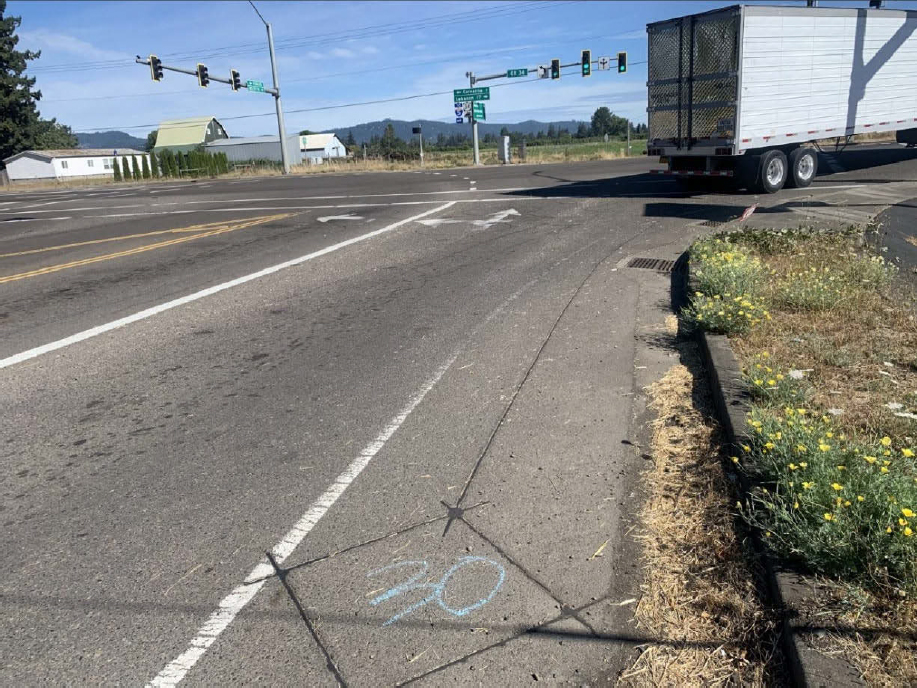
The working principle of inductive loop detectors is similar for detecting non-motorized traffic. Whenever metallic objects (e.g., bicycles) pass over the loops, currents are induced in the wire loops, and a wave signal is sent to the controller indicating the passage or presence of a bicycle. The waveform of the signal can vary depending on the speed and metallic components of the bike. The loops can detect and count bicycles and other micromobility devices that travel on bicycle lanes at signalized intersections; however, not all signal controllers are able to process and gather loop count data (Kothuri et al., 2012). Figure 3 presents an example of a diamond-shaped inductive loop for bicycles located on the shoulder.
In general, inductive loops for bicycles typically need to be placed on an exclusive facility so that they do not inadvertently detect vehicles or miss bicyclists that do not travel over the detector. Though loops can also be installed on shared-use paths and other facilities with mixed traffic, their accuracy tends to be higher on exclusive bicycle lanes (Nordback et al., 2011). In restricted facilities such as side paths and trails, loops can be combined with other detectors, such as infrared sensors, to count both bicyclists and pedestrians (Tolford et al., 2019).
STRENGTHS AND WEAKNESSES
Table 2 summarizes the main strengths and weaknesses of inductive loops detectors. The table was created by synthesizing information from various guides, past studies, and validation findings from NCHRP Project 03-144. For clarity, strengths and weaknesses are categorized into three groups: (a) those applicable to both modes, (b) those specific to motorized traffic, and (c) those specific to non-motorized traffic. Similar tables are provided for the other types of traffic signal equipment described in the remaining chapters of this guide.
Table 2. Strengths and Weaknesses of Inductive Loop Detectors.
| Strengths | Weaknesses |
|---|---|
| Motorized and Non-Motorized Traffic | |
|
|
| Motorized Traffic Only | |
|
|
| Non-Motorized Traffic Only | |
|
|
The validation results from NCHRP Project 03-144 revealed that the accuracy of motorized and non-motorized traffic volumes obtained from inductive loop detectors varies significantly (weighted mean absolute percent error [WMAPE] = 4.0% − 45.5%) based on multiple factors, with the most important being thorough inspection of the installation process and regular maintenance and calibration of the equipment (Klein and Kelley, 1996; Dahlin et al., 1997; Minnesota Department of Transportation (MnDOT) and SRF, 1997; Middleton et al., 1998). The location of loops (e.g., advance versus stop bar detectors) with respect to the stop bar
and the beginning of turn lanes has a higher impact on motorized traffic volume accuracy than loop shape (Milazzo et al., 2001; Guin, 2014).
Like many sensors, loop detectors may undercount or overcount vehicles. Common causes of undercounting are:
- Stop-and-go traffic: In stop-and-go traffic, closely spaced vehicles passing over a detector at the same time can be counted as a single vehicle, leading to undercounts. This often results in accurate counts during off-peak times and undercounts during peak conditions. This issue is more pronounced with stop bar detectors, especially long loops; however, long vehicle queues can also affect the counting accuracy of short advance loops. Figure 4 shows an example of benchmark and loop detector counts obtained from advance and stop bar detectors in Washington. The counts from stop bar detectors tend to be undercounted, especially when traffic volumes increase.
- Short vehicle presence times: If vehicles pass too quickly over the detector, especially at high speeds, the loop might not register them properly, causing undercounting.
- Loop malfunction or sensitivity issues: If a detector is not functioning properly or is not sensitive enough, it may fail to detect smaller vehicles like motorcycles or bicycles, leading to undercounts.
- Detector misalignment: If a loop is not correctly aligned with the lane or roadway, it may miss vehicles that are partially or completely out of its detection zone.
- Equipment calibration issues: Poor calibration or configuration errors can result in missing some detections.
- Environmental factors: Bad weather (e.g., snow) or poor pavement conditions (e.g., potholes and surface wear) can interfere with proper vehicle detection.
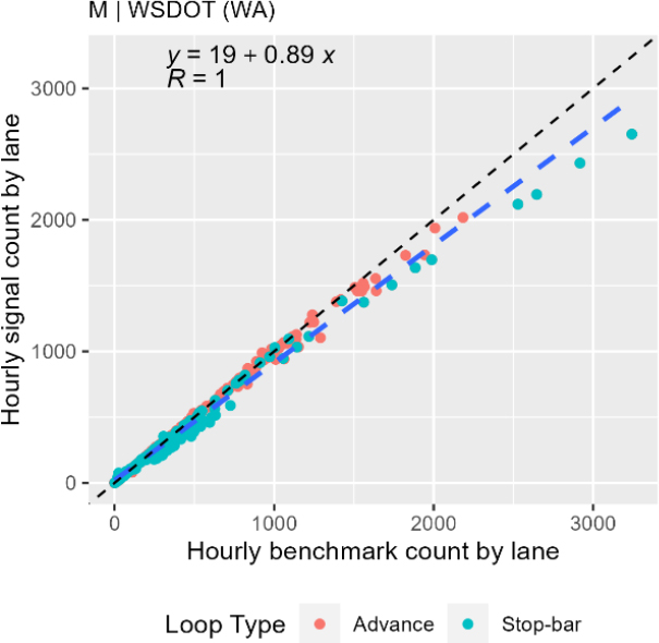
Note: WSDOT = Washington State Department of Transportation
Common causes of overcounting are:
- Turning maneuvers: Vehicles turning left from cross street can be detected by the stop bar loop detector on the through movement, leading to an overcount of vehicles on the through movement.
- Double-counting vehicles: In some cases, especially with multiple lanes or at lane-change points, a vehicle may trigger the detector twice, resulting in an overcount.
- Phantom detections due to electrical interference: Electrical noise or interference from adjacent detectors, nearby power lines, or other equipment may cause the loop to register false detections.
- Access points between advance detectors and intersection: Advance detectors can overcount through-moving vehicles if they turn into an intermediate access point (e.g., driveway) before reaching the intersection.
RECOMMENDED PRACTICES
Several European countries that have established installation and maintenance procedures and use high-quality materials have experienced a very small number of equipment failures, extended the life of loops, and reported positive feedback regarding the accuracy of the loops (Dahlin et al., 1997). Drawing on findings and recommendations from prior research, as well as validation results from NCHRP Project 03-144, the following sections provide recommended practices and ideal characteristics of loop detectors and data for traffic monitoring usage.
Installation and Materials
- Installation depth and sealing: Install detectors carefully according to specifications at the correct depth (typically 1–2 inches below the surface) and seal them properly with high-quality materials to prevent water infiltration, physical damage, and signal loss (Dahlin et al., 1997). Improper depth or sealing can lead to detector failure and inaccurate counts.
- High-quality materials: Use high-quality, durable materials that have a long lifespan (Dahlin et al., 1997). For example, high-quality shielded cables can minimize electromagnetic interference and signal degradation.
- Protected lead-in wires: Place lead-in wires in a waterproofed conduit approximately 18 inches (45 cm) below the ground surface. Many manufacturers recommend grounding the lead-in cable at the cabinet by connecting the shield to the earth ground terminal and insulating the cable within the pull box. This setup ensures that electrical disturbances and interference are safely grounded without impacting the loop lead-in cable (Middleton et al., 1998).
- Weather-resistant components: Use materials and sealants that can withstand extreme weather conditions to prevent damage and ensure longevity. Ensure all loop components, including wires and sealants, are weather resistant and can operate accurately across a wide range of temperatures. Avoid using sharp-edged tools to push wires into saw cuts and do not allow any splices to occur outside pull boxes.
- Wired connections: Use wired connections between signal cabinets and central servers because they tend to provide a more stable, interference-free transmission than wireless connections (Guin, 2014). Wired systems reduce the likelihood of signal loss, ensuring continuous data collection.
- Electrical testing: Conduct all electrical checks before and after sealing. For example, verify loop continuity, measure loop electrical resistance, and assess loop insulation resistance according to manufacturers’ specifications.
- High-quality amplifier cards: Choose high-quality amplifier cards that minimize false detections and improve overall sensitivity, ensuring accurate data collection for both motorized and non-motorized vehicles. High-quality amplifiers can better distinguish vehicle presence, even in challenging conditions, and are especially helpful in detecting smaller, non-motorized vehicles like bicycles.
- Pavement reinforcement: Reinforce potentially deteriorated and poor-quality pavement prior to loop installation to ensure durability and structural support. Where feasible, consider installing a pre-formed loop beneath the reinforced pavement surface to improve resilience and extend the loop’s operational life. A pre-formed loop is a type of loop detector that comes as a preassembled, molded unit, often with protective casing. Instead of being directly sawcut and embedded into the pavement like traditional loops, pre-formed loops are installed beneath the pavement surface, either during initial construction or as part of a resurfacing project.
- Loop placement to avoid cracks: Avoid installing loops directly over existing pavement joints or wide cracks whenever possible. If positioning near a joint is necessary, ensure there is sufficient slack in the wire to accommodate joint movement (Middleton et al., 1998).
- Independent loop wiring: Wire loops independently to prevent crosstalk between adjacent loops (Blanc et al., 2015). Such wiring reduces interference and ensures that the data collected from each loop are specific to the lane or area it monitors, improving overall accuracy.
The following practices are recommended for counting non-motorized traffic:
- Dedicated bicycle detection loops: Install loops in dedicated bike lanes, shoulders, or cycle tracks to avoid interference from motorized traffic (Nordback and Janson, 2010; Nordback et al., 2011; Veenstra et al., 2013; National Association of City Transportation Officials, 2014; Ryus et al., 2014; Blanc et al., 2015; Nordback et al., 2016).
- Advance bicycle detection: Avoid installing loops at the stop bar for bicycle detection. Advance detectors, placed before the stop bar, are more effective at counting moving bicycles and prevent false detections caused by bicycles stopping or lingering at the intersection (Shah et al., 2020).
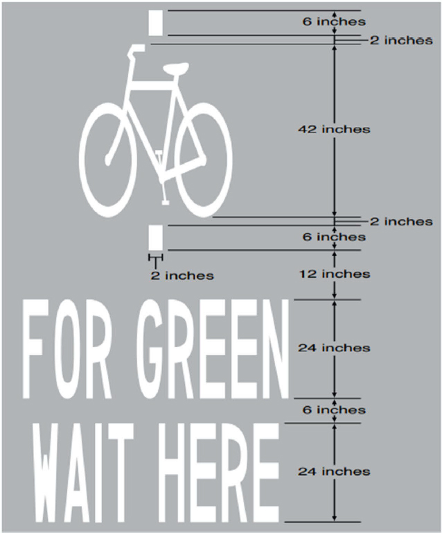
- Pavement marking guidelines: Use the Manual on Uniform Traffic Control Devices’ pavement marking guidelines (Figure 5), which indicate the optimum position for a bicycle to actuate a signal (FHWA, 2023).
- Electrical interference avoidance: Avoid installing loop detectors at locations with electrical interference problems, such as close to power lines and other inductive loops. Electrical interference can be measured prior to installing loops using appropriate equipment (Nordback et al., 2011).
- Compatibility with signal controllers: Verify if existing traffic signal controllers are capable of processing loop count data prior to installing loops for bicycle detection and counting (Nordback et al., 2011). Incompatible systems may not capture or transmit accurate counts.
Calibration and Maintenance
- Initial calibration: Calibrate the detectors accurately during installation to ensure correct vehicle count and classification. In case of non-motorized traffic, ensure that the intended non-motorized users are being detected and the sensor is not registering false positives from nearby motor vehicles. Loop sensitivity should be calibrated to the minimum sensitivity required for consistent bicycle detection (Blanc et al., 2015).
- Periodic recalibration: Recalibrate the system to adjust for changes in hardware, software, traffic patterns, pavement conditions, and environmental factors. Detector loops should be validated and checked under the following conditions to ensure accurate and reliable data collection:
- After pavement repaving or resurfacing: Repaving can impact loop functionality or even damage loops, so validation ensures they are accurately detecting vehicles post-repair.
- When new amplifier cards or detector equipment are installed: Changes in equipment can alter detection sensitivity or calibration, so checks ensure compatibility and accuracy (Nordback and Janson, 2010).
- After significant traffic pattern changes: Changes, like lane realignments, could affect loop performance, requiring recalibration to maintain detection precision.
- Following extreme weather events: Severe conditions (like flooding and freeze-thaw cycles) can damage loop integrity, necessitating validation.
- When detection issues are suspected: Unexpected volume counts or irregular data should trigger a validation to confirm proper loop operation.
- Routine maintenance: Maintain equipment according to the manufacturer specifications. Conduct regular inspections to check for wear and tear, ensure the loop’s integrity, and identify changes in sensitivity. Promptly address any issues, such as loop sealant deterioration, loop wire splicing, moisture, pavement cracking, deteriorated insulation, corroded splices, and detuned amplifiers (Bikowitz and Ross 1985; Chen and May 1987).
Location, Shape, and Number
- Strategic location: Install loops upstream of the beginning of turn lanes or downstream from the intersection (Guin, 2014; Guin et al., 2016). This reduces the likelihood of miscounting due to lane changes and turning movements.
- Vehicle queuing avoidance: Install loops at locations to avoid queuing of stopped vehicles within the detection zone of loops (Guin, 2014; Guin et al., 2016). Queuing vehicles, especially during peak hours, can remain in the detection zone for extended periods, which can cause counting issues.
- Lane-by-lane loops: Choose lane-by-lane loop configurations over single-channel configurations because the former provide more accurate traffic volumes (Malinovskiy et al., 2009; Milazzo et al., 2001; Smaglik et al., 2005). Single-channel configurations, which cover multiple lanes, often result in less accurate counts due to overlapping vehicle detections.
- Distance from access points: Avoid, if possible, major intermediate access points (e.g., commercial driveways) that generate or attract traffic between advance detectors and the downstream intersection. If a major driveway exists, position the loop at least 50 ft (15 m) downstream from the driveway and at least 200 ft (60 m) upstream of the stop bar (Klein et al., 2006).
- Vehicle weaving avoidance: Place loops at locations that avoid, to the extent possible, weaving and irregular paths of vehicles that can affect volume accuracy (Guin, 2014; Li et al., 2014). Irregular movements, such as lane changes or erratic driving behavior, can lead to incorrect volume counts and reduce the overall accuracy of the data.
- Dual loops: Select dual loops because they tend to provide more accurate motorized volumes than single loops and can also collect vehicle classification data. Dual detectors can also measure vehicle speed more accurately than single detectors by using the time it takes for a vehicle to pass from one detector to the other. Having two detectors reduces the likelihood of missing a vehicle since the second detector can serve as a backup if the first fails to detect a vehicle. Dual detectors help minimize false alarms by verifying the presence of a vehicle
- with two detection points. They can measure queue lengths more accurately, which helps optimize signal timings and reduce wait times.
- Short over long loops: Avoid using volume data from long loops at the stop bar because they tend to undercount vehicles (Milazzo et al., 2001). Shorter loops are more effective in capturing each vehicle that enters the detection zone.
- Spacing from roadway features: Position loops at least 10 ft (3 m) from manholes, water valves, or other roadway appurtenances to minimize the risk of loop disturbance during maintenance work (Klein et al., 2006). This spacing helps ensure loop durability and uninterrupted functionality.
- Loop shape for bicycle counting: Avoid parallelogram- and quadrupole-shaped inductive loops for non-motorized traffic because these loops tend to have high errors in mixed traffic conditions (Nordback and Janson, 2010; Nordback et al., 2011; Veenstra et al., 2013). Choose diamond-shape loops (Figure 3) for bicycle detection and counting. Diagonal or diamond-shaped loops provide a broader detection field than square loops aligned with the direction of traffic flow, increasing the likelihood of detecting bicycles, especially when these are not directly above the loop center (Middleton et al., 1998).


