Leveraging Existing Traffic Signal Assets to Obtain Quality Traffic Counts: A Guide (2025)
Chapter: 3 Video-Based Systems
CHAPTER 3. VIDEO-BASED SYSTEMS
INTRODUCTION
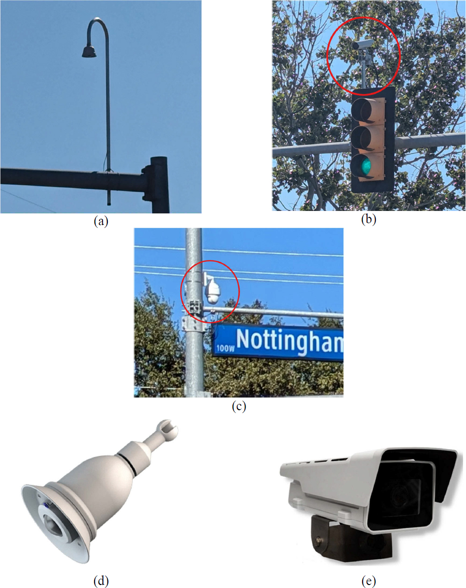
Video-based systems (Figure 6) are non-intrusive technologies that can provide remote viewing, offer surveillance capabilities, and collect several data outputs. These systems are increasingly used at signalized intersections for traffic detection and signal control, and in recent years, for motorized and non-motorized volume data collection. A typical video processing system consists of one or more fixed or PTZ cameras and a built-in or external processor for analyzing video images and translating them into traffic flow information (Klein et al., 2006). The most common types of cameras are (a) standard video optical monochrome or color cameras; and (b) 360-degree cameras, which can view all intersection approaches. The 360-degree cameras may also be used in combination with advance cameras or thermal sensors. Thermal cameras are described in Chapter 6: Infrared Sensors.
In some systems, the processors are integrated into the cameras, allowing them to analyze video data on-site. In other systems, processing may occur in signal cabinets or other dedicated processing units (e.g., external servers). Video-based systems use a variety of methods to detect and count vehicles, such as artificial intelligence (AI) and machine learning, video image processing, and product-specific algorithms. In general, these methods analyze changes across groups of pixels between successive frames, disregarding gray level or color changes in the
stationary background. When changes are detected, the processor calls the signal controller. The processor can be configured to output signals that simulate a loop detection system, including pulse, presence, delay, and extension signals (Balke et al., 2023).
The two main counting methods from videos are region of interest (ROI) and line of interest (LOI) counting. ROI counting estimates the number of vehicles in a selected region at a specific time, while the LOI method counts vehicles crossing a designated detecting line (Xiong et al., 2017). The ROI method involves setting up virtual detectors, also known as detection zones, at selected areas within a video frame where vehicle presence is monitored continuously. By tracking vehicles as they enter, move through, or exit this area, ROI counting provides an estimate of the number of vehicles present at a specific moment. For example, Figure 7 shows three sets of virtual detectors placed at different locations along an intersection approach to count and detect vehicles (Wu et al., 2021). The red detectors at the stop bar are primarily used to count vehicles, the blue detectors placed before the stop bar collect occupancy data, and the advance green detectors are configured to collect occupancy data. Some manufacturers recommend placing the red (volume) detectors after the stop bar to detect and count moving vehicles as they enter the intersection.
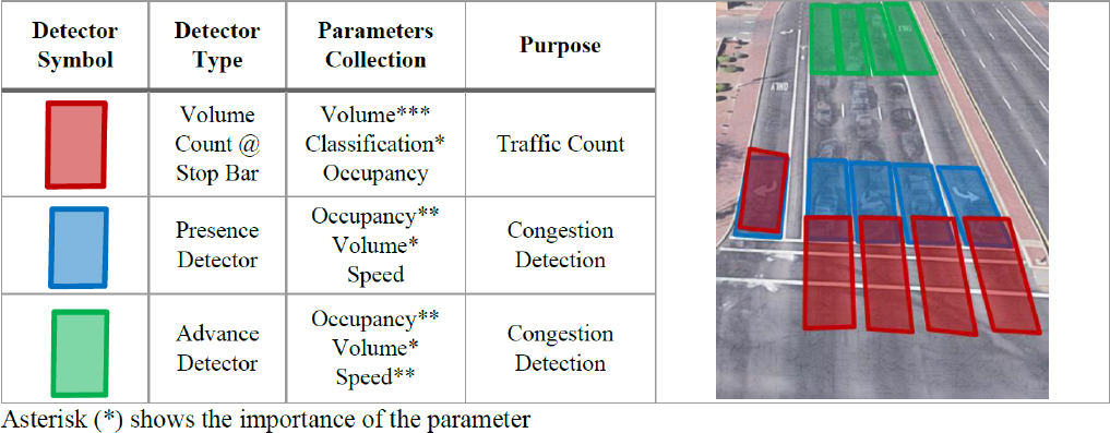
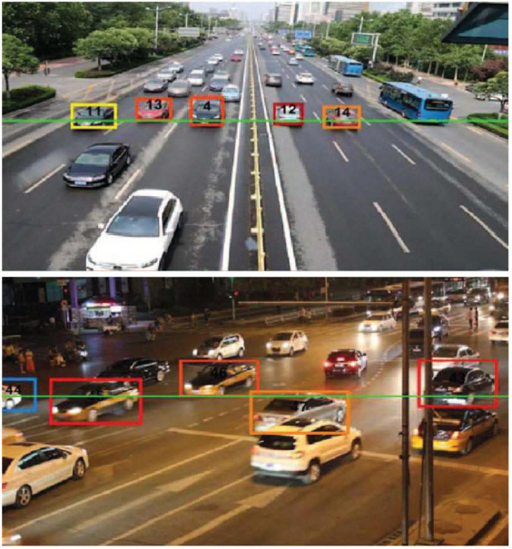
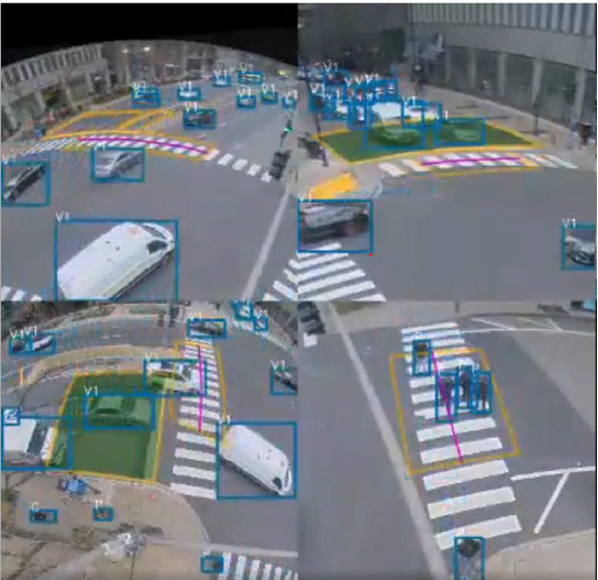
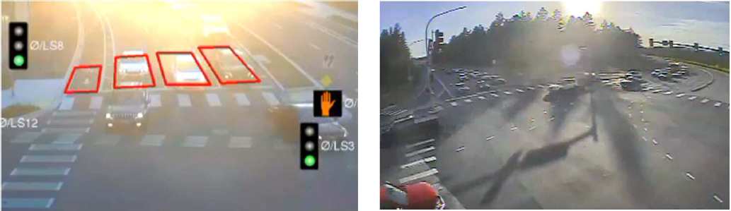
Figure 8 and Figure 9 illustrate examples of virtual detectors configured to detect and count vehicles. When a vehicle passes over a detector, the latter changes color (e.g., from black to green in Figure 8, and from yellow to green in Figure 9), indicating activation.


LOI counting, on the other hand, focuses on counting vehicles as they cross a specified line within the video frame. This virtual line acts as a threshold, counting each vehicle that
crosses it as it moves along the roadway. Figure 10 demonstrates an example of vehicle tracking by using a counting line covering multiple lanes (Li et al., 2020).
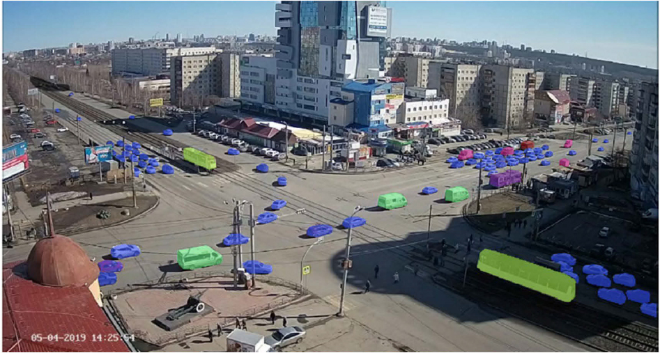
In addition to modern cameras with built-in microprocessors or cameras connected to processors installed in signal cabinets, volumes can be extracted from videos recorded by closed-circuit television (CCTV) systems. CCTV, known as video surveillance (Kumar and Svensson, 2015), has been widely used for security or monitoring purposes at signalized intersections. CCTV can provide continuous videos 24/7 throughout the year. Even though CCTV systems cannot provide volume data directly, image processing methods can extract real-time or offline traffic volumes from existing videos. For example, Figure 11 shows an image from a CCTV-based system, which identifies, tracks, and classifies vehicles (Fedorov et al., 2019) using region-based convolutional neural networks, which is a deep learning architecture for object detection.
Some sensors use a traffic detection module to detect vehicle presence but may require a separate traffic data collection module or a special subscription to gather data such as volumes, speeds, and density (Wu et al., 2021). The primary purpose of a traffic detection module is to help control traffic signals by monitoring when vehicles are waiting at an intersection or passing specific points on the roadway. This module works by detecting an object’s presence, which triggers the traffic signal controller to initiate appropriate signal phase changes (e.g., changing from red to green) or actuations (e.g., extending a green phase if vehicles are still detected in the queue). Traffic data collection modules extend the capabilities of a system by enabling more detailed measurements but often require specialized hardware, software, or a subscription to enable data collection features.
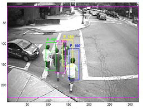
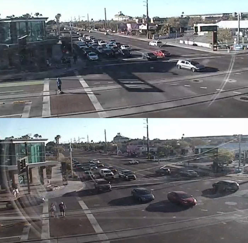
The working principle of automated video-based systems for counting non-motorized traffic is similar (Figure 12). Though some cameras can count only non-motorized traffic, others can differentiate between non-motorized and motorized traffic (Shah et al., 2020). In many cities, existing traffic monitoring cameras can be upgraded to count not only motor vehicles but also non-motorized traffic (e.g., Iteris’s SmartCycle). Some cameras are able to detect screen line and turning movement volumes at intersections, and others can also collect other data such as speed, travel direction, and traveler-specific characteristics (Ryus et al., 2014; Shah et al., 2020). Automated video-based systems can be used for both short- and long-term counting. This technology requires minimum human effort for counting non-motorized volumes. Figure 12 shows an example of a video-based system identifying pedestrians, while the system shown in Figure 13 detects both motorized and non-motorized traffic.
STRENGTHS AND WEAKNESSES
Table 3 summarizes the main strengths and weaknesses of video-based systems for counting motorized and non-motorized traffic.
Table 3. Strengths and Weaknesses of Video-Based Systems.
| Strengths | Weaknesses |
|---|---|
| Motorized and Non-Motorized Traffic | |
|
|
| Motorized Traffic Only | |
| No additional strengths and weaknesses beyond those applicable to both modes | |
| Non-Motorized Traffic Only | |
|
|
The validation results from NCHRP Project 03-144 revealed that the accuracy of motorized traffic volumes obtained from video-based systems varied significantly (WMAPE = 1.4% − 33.7%) by vendor, equipment model, and intersection. The mounting height, location, placement, and proper calibration of a camera are crucial to the optimal performance and accuracy of the outputs (Ishak et al., 2016). Video-based systems are affected by external factors that result in poor visibility and obstructed camera views. Many cameras tend to undercount vehicles, but there are cases where overcounting is observed.
The most common causes of undercounting are:
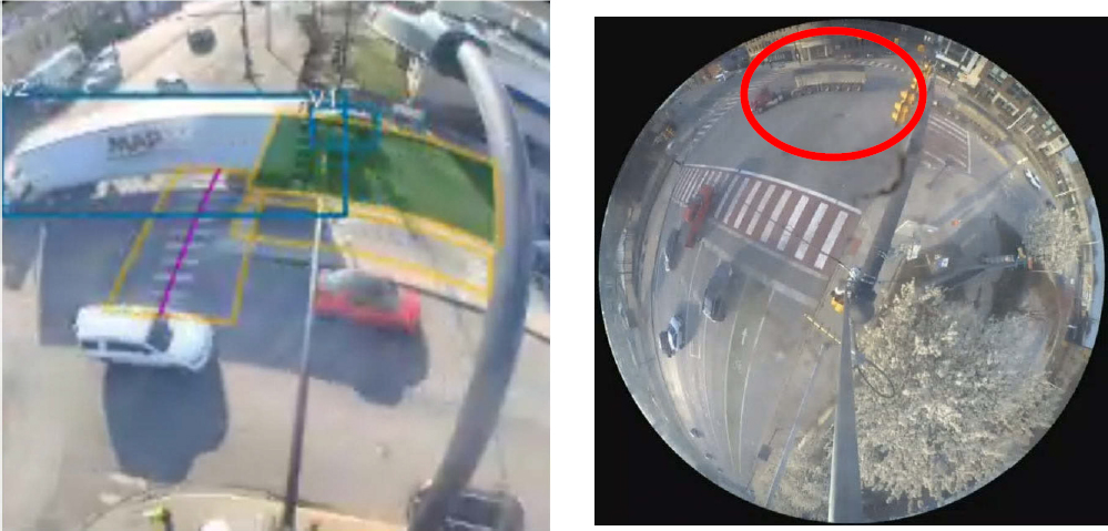
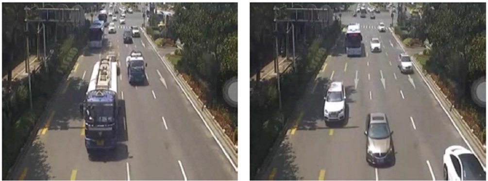
- Occlusion: Vehicles blocked by other usually larger vehicles, like trucks or buses (Figure 14), prevent accurate counting, especially in congested conditions or approaches with multiple lanes (Moshiri and Montufar, 2017; Smaglik et al., 2010). This problem is more pronounced in lanes farthest from the camera, where the vertical field of view is limited, especially when two or more adjacent lanes allow the same vehicle movement (e.g., two left-turn lanes or two through lanes). The problem is often observed when cameras are not installed high enough, particularly in large intersections.
- High traffic volumes: The counting accuracy of video-based systems tends to decrease as traffic volumes increase, primarily due to occlusion as described above (Ishak et al., 2016).
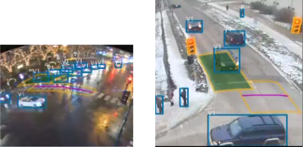
- Adverse weather conditions: Heavy rain, snow, or fog reduces the camera’s ability to detect vehicles (Figure 15). Rain may also cause reflections, leading to counting problems. Strong winds can shake or misalign cameras and cause obstructions due to leaves and debris.
- Improper camera placement: If the camera view does not fully cover the lanes of interest, or if the camera is placed too close or too far, vehicles may be missed.
- Improper placement and calibration of virtual detectors: Suboptimal location and shape of virtual detectors may undercount vehicles, especially in turning lanes. Even when virtual detectors are set up and calibrated according to specifications, errors can occur when right- or left-turning vehicles decide to go straight after entering the intersection, and vice versa.
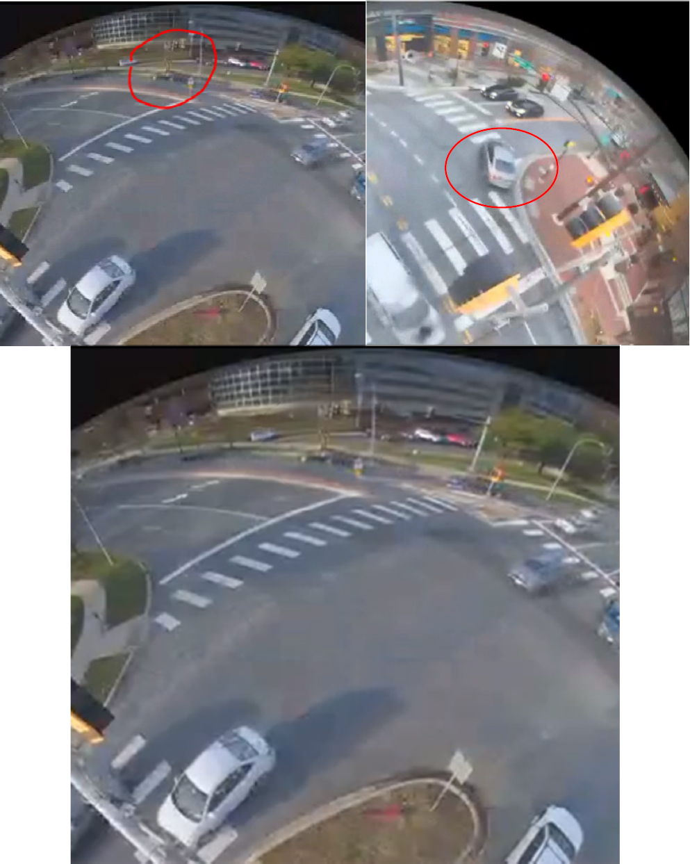
- Shadows: Shadows of trees, vehicles, and buildings can result in counting issues (Figure 16 and Figure 17).
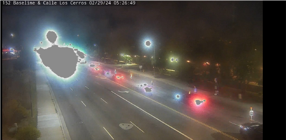
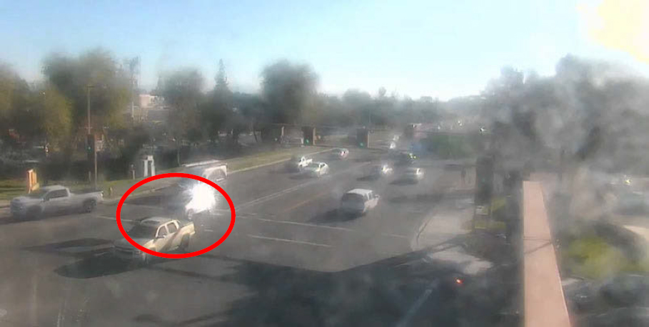
- Bright lights and reflections: Bright sunlight (Figure 18), vehicle headlights (Figure 19), flickering from artificial lights, wet pavement, or glare on the lens can obscure or distort vehicles, causing missed detections. Vehicle reflections caused by sunlight can also lead to counting errors (Figure 20).
- Dirty lenses: Camera lenses can become dirty due to water, icicles, salt grime, and spiderwebs, causing counting issues (Figure 21).
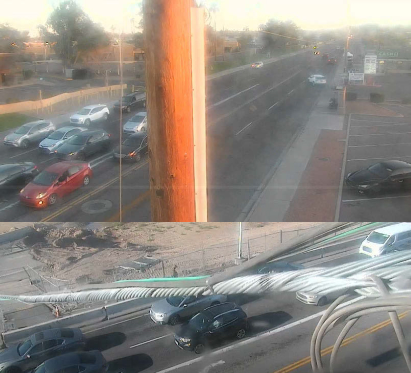
- Fixed objects: Cameras views can be obstructed by fixed objects such as poles, gantries, signs, and cables (Figure 22).
- Poor lighting conditions: Low light during nighttime, as well as during the transition from day to night and from night to day, may cause undercounting issues.
- Poor contrast with background: Poor contrast between vehicles and the road can cause undercounting (Figure 23).
- Power or network outages: Interruptions in power or network connectivity can lead to gaps in data collection.
- Low frame rate: Low frame rates may not capture every vehicle during peak hours, leading to missed detections.
- Vehicle speed and space: Fast-moving vehicles may pass through detection zones too quickly to be counted accurately. Closely spaced vehicles may be counted as one, primarily during high-volume periods.

The most common causes of overcounting are:
- False detections from shadows and reflections: Shadows from moving vehicles or reflections from windows and other surfaces can be counted as additional vehicles.
- Debris or small moving objects: Moving objects like leaves, birds, or animals can lead to overcounting (Masoud and Papanikolopoulos, 2001; Shen et al., 2019).
- Camera movement or vibration: Vibrations from wind or passing traffic can cause the camera to move slightly, leading the system to interpret the movement as a new object.
- Ghosting or blurred frames: Low-quality frames due to rapid movement or suboptimal image processing can result in multiple detections of the same vehicle.
- Poor calibration: Inaccurate initial setup or calibration may result in virtual detectors being placed too wide or overlapping lanes, causing overcounting.
- Reflections: When roads are wet, reflections from vehicles can create ghost images that the system interprets as additional vehicles.
- Vehicle size misinterpretation: Large vehicles, like trucks or pick-ups with trailers, may be detected as multiple vehicles depending on the system’s detection parameters.
- Turning movements: Stop-and-go traffic on turning lanes can result in overcounting in certain types of equipment (MnDOT and SRF, 1997).
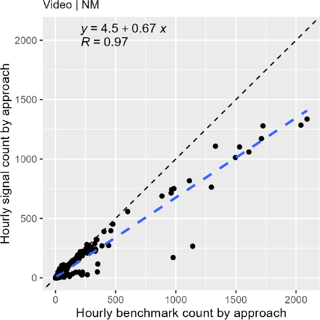
The NCHRP 03-144 validation results showed that the accuracy of signal equipment for counting non-motorized traffic was lower than that for motorized traffic (WMAPE = 3.6% − 93.7%). Most video-based systems undercounted non-motorized users. This undercounting trend is observed in the scatterplot shown in Figure 24, which displays all non-motorized hourly volumes from the study intersections equipped with video-based systems.
The low accuracy and the undercounting issues can be attributed to several factors:
- Primary optimization for motor vehicle detection: Most signal equipment is designed and optimized specifically for detecting motor vehicles. Vehicle detection technologies have been in use for decades and are highly refined, with standardized installation and calibration procedures that help achieve high accuracy.
- Camera view limitations: Existing cameras installed to detect vehicles may have a limited view of pedestrian and cyclist pathways or crosswalks, particularly on large intersections, leading to missed detections.
- Challenges due to size: Pedestrians and bicyclists are smaller than vehicles, making them more difficult to detect with technologies calibrated for larger objects.
- Lower reflectivity: Pedestrians and bicyclists wearing dark or non-reflective clothes can be harder to detect compared to vehicles, which tend to be more reflective due to their metallic surfaces and glass windows.
- Irregular movement patterns: Non-motorized users often move irregularly, crossing streets at different points, angles, and speeds, which complicates accurate detection and counting.
- Groups of pedestrians: Pedestrians frequently move in groups, making it challenging for sensors to distinguish and accurately count individuals within a group.
- Obstruction by vehicles and infrastructure: Non-motorized traffic can be easily obscured by passing vehicles, infrastructure elements, or other pedestrians and bicyclists, resulting in missed counts.
Despite these issues, some video-based technologies, primarily new products that use advanced AI technologies, have shown great potential in both differentiating and counting pedestrians and cyclists at intersections (Ozan et al., 2021). Video-based systems are capable of accurately counting the flow of bicycles for various movements having distinct origins and destinations, even in challenging environments (e.g., intersections) where mixed traffic is present (Zangenehpour et al., 2015).
RECOMMENDED PRACTICES
Proper installation, thorough calibration for counting motorized and non-motorized traffic, and frequent maintenance of the equipment are keys to improving data accuracy. General recommended practices and ideal characteristics of video-based systems and data for traffic monitoring use are described below.
Installation and Calibration
- Mounting height and positioning: Position cameras high enough at strategic locations per manufacturer specifications to avoid potential occlusion caused by large vehicles (Moshiri and Montufar, 2017; Smaglik et al., 2010). Attention should be given to minimize potential occlusion of left-turning vehicles when the camera views the approach from an angle. The recommended height varies by vendor and type of camera. Some vendors recommend a mounting height of 16 to 23 ft, whereas others (e.g., some vendors of 360-degree cameras) suggest a minimum height of 30 ft. The Traffic Signal Program Handbook suggests a 1-to-10 ratio of the camera’s mounting height to the distance from the detection zone (Balke et al., 2023). It also recommends that the ideal mounting location should be in front of the vehicles approaching the stop bar, centered on the monitored approach. However, this may not apply to 360-degree cameras since manufacturers typically suggest using one camera per
- intersection. The recommended mounting height of a camera generally increases as its position is offset farther from the center of the approach, when intended for advance detection, and as the distance from the stop bar increases (e.g., in large intersections). In general, mounting cameras at a higher elevation ensures a clear line of sight across the intersection and minimizes issues such as occlusion and glare from the sun or vehicle headlights (Ishak et al., 2016).
- Unobstructed field of view: Ensure the field of view is free from obstructions such as trees, utility poles, signal heads, gantries, cables, signs, and buildings. Even minor obstructions can hinder the camera’s ability to detect vehicles or non-motorized traffic accurately, leading to gaps in data or false readings.
- Horizon excluded from field of view: Avoid including the horizon in the camera’s field of view to prevent false detections of irrelevant objects and reduce the impact of reflections and lighting changes on detection accuracy.
- Detection range: Ensure the farthest detection zone from the camera falls within the maximum range recommended by the equipment manufacturer (typically 300–400 ft). Additional advance cameras may be needed to accurately detect vehicles away from the camera. Some agencies do not use cameras installed at the intersection to detect vehicles 300 ft or more from the stop bar (Bonneson and Abbas, 2002).
- Secure and stable mounting: Mount cameras securely to prevent shaking or misalignment due to environmental factors such as strong winds and mechanical factors such as vibrations from passing heavy vehicles or nearby machinery. Proper stabilization helps prevent shaking, which can lead to blurred images, missed detections, and inaccurate data. Using vibration-dampening materials, ensuring stable and tight mounting, and verifying alignment are recommended to maintain optimal camera performance.
- Number of cameras: Consider installing one optical camera per approach, rather than one camera per intersection, to improve data accuracy, particularly in large intersections and high-volume approaches (Wu et al., 2021). This setup improves accuracy by focusing on specific lanes or directions, especially when traffic flows are high. Consider using two 360-degree cameras in large intersections, instead of one. If two cameras are used, consider installing them on opposite corners of the intersection. The 360-degree cameras can be mounted on the same bracket with other sensors (e.g., optical or thermal cameras). The Traffic Signal Program Handbook recommends that in single-camera installations, the camera should be installed:
- On the interior side of the intersection.
- 30 ft or more above the roadway.
- 75 ft or less from the center of the intersection.
- 150 ft or less from the farthest stop bar (Balke et al., 2023).
- Lighting conditions: Consider improving lighting conditions by installing overhead illumination to maintain equipment performance during nighttime or low-visibility conditions and to reduce the impact of vehicle headlights on counting accuracy (Bonneson and Abbas, 2002; Medina et al., 2009). Data accuracy can be improved by minimizing temporal variations in illumination (Somasundaram et al., 2009). Thermal cameras perform better than standard cameras in low-light conditions and should be considered as an alternative.
- Virtual detector setup: Set up the appropriate number and type of virtual detectors, if applicable, at the locations recommended by each manufacturer. Virtual detectors are used to create detection zones within the video feed.
- Initial calibration and validation: Perform initial calibration of detection zones according to each manufacturer’s recommendations and verify that they capture the intended data. Ideally, system functionality and data accuracy should be checked during various periods of the day—early morning, midday, late afternoon, and nighttime. Adjustments may be needed to ensure the detectors are properly aligned with traffic flows. For instance, some vendors suggest using pulse LEDs to check whether a system is detecting vehicles. Brief 15- to 30-minute manual validations can help verify that the system is functioning as expected.
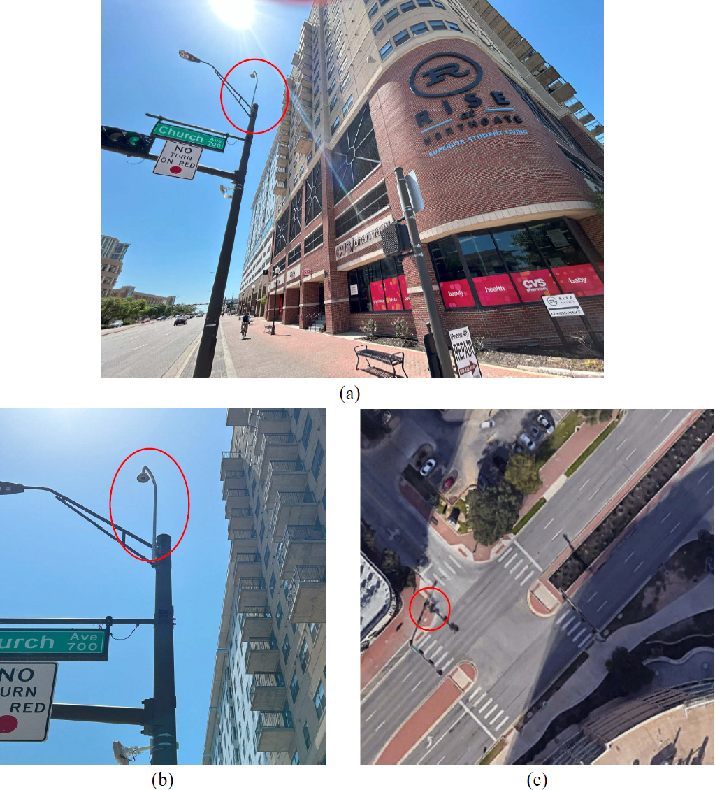
- Dedicated non-motorized traffic monitoring: Consider installing additional cameras for detecting and counting non-motorized traffic if the existing camera views of crosswalks and sidewalks are limited or obstructed. Cameras dedicated to monitoring pedestrians and bicyclists are generally more effective than those optimized for vehicle detection. For example, Figure 25 shows a scatterplot of the most accurate non-motorized traffic signal volumes (WMAPE = 3.6%) validated in NCHRP Project 03-144. The high accuracy of this video-based system can be attributed to several factors. Two cameras were installed on opposite corners of an intersection by the Texas AandM Transportation Institute (TTI) and configured specifically to count pedestrians and bicyclists, not vehicles. Also, after installing the cameras, the TTI team spent longer than usual time calibrating them and ensuring that the data were accurate. Other factors also likely contributed to the high accuracy at this location. As shown in Figure 26, the cameras were installed at high and strategic positions, well above the traffic signal mast arm, providing a clear and unobstructed field of view. The mast arm shown in Figure 26 is located after the crosswalk, ensuring it does not block the camera’s view. Additionally, the intersection is well illuminated with three light poles, one on each traffic signal pole.
- Pedestrian behavior: Take into account typical pedestrian walking behaviors and patterns before installing cameras to enhance pedestrian detection accuracy. For instance, pedestrian counts may be missed near transit stops since individuals often cross at the bus stop rather than at the designated signal.

Equipment Characteristics
- Hardware, software, and subscriptions: Obtain appropriate hardware, software, and/or subscriptions for traffic volume data collection. For example, some modern video-based systems require a separate traffic data collection module or subscription to collect traffic volumes (Wu et al., 2021).
- High-quality video: Ensure that cameras capture high-quality video and/or detailed images for accurate traffic detection and classification. Poor-quality footage can result in missed detections or incorrect vehicle classification, especially for smaller or faster-moving vehicles.
- Overlapping coverage areas: Consider overlapping coverage areas with multiple cameras to provide multiple angles for verification and ensure no traffic is missed. Overlapping also provides redundancy in case of camera failure. If multiple cameras are used, ensure that vehicles are not counted multiple times.
- Wide field of view: Use cameras with a wide field of view to minimize blind spots in the detection area, thereby capturing a greater range of traffic.
Maintenance
- Routine inspections: Perform regular maintenance checks (e.g., every six months or more often if warranted) to ensure the equipment is functioning correctly. Evaluate the effect of changes in the sun’s position on count accuracy and make necessary adjustments (Bonneson and Abbas, 2002). Inspect the lenses for dirt or debris, which can obstruct the view, and clean them if needed (MnDOT and SRF, 1997).
- Camera alignment: Align cameras properly to ensure that they are focused on the correct lanes or approaches. Misaligned cameras can lead to poor detection accuracy or missed traffic, especially in multilane or complex intersections.
- Vegetation and obstruction maintenance: Conduct regular trimming of vegetation and ongoing monitoring of potential new obstructions (e.g., growth of nearby trees or installation of new structures) to maintain an uninterrupted line of sight for effective data collection.
- System calibration and testing: Test and recalibrate cameras as part of the maintenance checks to ensure accurate vehicle detection and tracking (Guin, 2014; Ishak et al., 2016). Environmental factors such as temperature fluctuations, lighting changes, and shifts in traffic patterns can affect the system’s accuracy over time, making periodic recalibration essential.


