Through-Running Regional Rail (2026)
Chapter: Recommended Changes to the TCQSM
each zone, with fewer train movement conflicts resulting in higher capacity. The interlockings at these stations often involve fewer switches and better track geometry, but they require wide station throats and significant investment in parallel track capacity away from the station itself.
A good U.S. example of a large, city-center station configured for through-running is Philadelphiaʼs 30th Street Station. It has tracks and platforms on two levels, both of which are set up primarily for through-running: the upper level (used by SEPTA Regional Rail trains) and the lower level (used by Amtrak and NJ Transit Atlantic City Line trains). Most trains run through the station; although some trains turn back at the station platforms, especially on the lower level. Other examples of through-running major stations include San Jose, CA; Dallas, TX; New Haven, CT; and Jamaica, NY (on the Long Island Rail Road). In Europe, examples of stations set up in a 100% through-running configuration include the Berlin Hauptbahnhof (main station) and the new Stuttgart21 Station in Germany.
The following large hub stations in North America have complex configurations and include both stub-end and through-running tracks to support a wide range of train traffic types:
- Chicago Union Station
- New York Penn Station
- Toronto Union Station
- Washington Union Station
Similar international examples include the following:
- Brussels-Midi Station
- London Bridge Station
- Sydney Central Station
Several examples also exist of legacy rail stations—both stub-ended and through-running—where a new RRM station has been constructed next to the legacy station to support through-running, metro-style service separate from the more complex operations and wider mix of train types that remain at the older station. The schematics shown in Figure 13 illustrate the separate-but-adjacent nature of these station configurations.
Stub-end legacy stations with an adjacent purpose-built new station to support through-running RRM service include the following:
- London Liverpool Street
- London Paddington
- London St. Pancras International
- Munich Hbf
- Paris Gare du Nord
Operational modes at large legacy train stations can include the following:
- 100% turnback
- 100% through-running
- Hybrid

Long Description.
The diagram presents two station configurations. The first configuration is labeled Stub-End Terminal with Adjacent Regional Metro and shows six platforms connected to tracks that end at the station. Below it, a separate metro track pair is shown with two platforms, one on each side of the tracks. The second configuration is labeled Through-Station with Adjacent Regional Metro and shows six platforms connected to tracks that continue through the station. Below it, a separate metro track pair is shown with two platforms, one on each side of the tracks.
RECOMMENDED CHANGES TO THE TCQSM
As described in the previous sections, recent planning initiatives across North America are shifting legacy commuter rail systems toward high-frequency, bidirectional, through-running service models that operate more like urban transit. These evolving systems, known as RRMs, often require a rethinking of how rail capacity is measured and planned. Other applications of through-running do not necessarily shift regional rail operations as radically toward metro-like operations but employ many of the same through-running principles.
The following proposed additions to Chapter 8 of the TCQSM are aimed at incorporating key capacity-related principles from global through-running best practices. Specifically, these changes emphasize the implications of consistent stopping patterns, clock-face scheduling, and infrastructure configurations (such as grade-separated junctions and trunk-branch layouts) on achievable throughput. All section references are to the most recent draft version of the TCQSM 4th edition chapter.
Section 8.4, Train Operations
In high-throughput, through-running regional rail systems, operating margins are optimized through standardized clock-face scheduling across branches, with precisely timed meets and merges at trunk entry points. This approach allows systems like the Munich S-Bahn to schedule 30 trains per hour through a two-track core with minimal conflicts or delays. Incorporating such scheduling strategies in North American systems can enhance reliability and reduce delay propagation in tightly packed urban cores.
Section 8.5, Rail System Capacity Methodologies
Through-Running Regional Rail
The trunk line capacity range of through-running regional rail systems has a higher ceiling than typical North American commuter rail systems. Through-running regional rail systems are characterized by trunk-and-branch operations where trains operate frequently and
bidirectionally through an urban core, connecting neighborhoods and suburbs on either side of the core. The through-running trunk connection often is created via new or upgraded tunnels or grade-separated rail corridors linking former stub-end terminals. These systems often operate with clock-face headways, standardized rolling stock, grade-separated junctions, and short dwell times, maximizing line capacity and offering metro-like service.
High-performing, through-running, RRM systems such as Parisʼs RER, Tokyoʼs Toei Asakusa Line, and Londonʼs Thameslink can support up to 24 trains per hour per track, enabled by some combination of moving-block signaling, higher-performing rolling stock, short station dwell times, and avoiding conflicting train movements. Some systems such as Munichʼs S-Bahn can support up to 30 trains per hour. Blended through-running operations, where many regional and intercity services share the same tracks to a common major station like Amsterdam Centraal or Brussels-Midi, typically support close to eight trains per hour per track on the trunk line, but closer to five trains per hour per track at the station platforms.
The high-performing, through-running RRM systems run on legacy right-of-way in outer areas and typically maintain exclusive or dedicated-use tracks through the core. A clear separation of service types (commuter vs. RRM) and investment in key bottlenecks (e.g., station leads, junctions, platform interfaces) are essential to achieve a high operational capacity.
In through-running, regional rail systems, the maximum achievable throughput is influenced by the trunk line itself and by how well the entire network functions as an integrated whole.
Specifically, capacity is defined by the combined performance of four interrelated components:
- The trunk line
- Major stations
- Interlockings and junctions
- The outlying network (including branches)
The component with the lowest effective throughput constrains the systemʼs overall capacity. For example, even a trunk line designed with advanced signaling and short headways could be underutilized if upstream junctions are flat and busy or when mixing with slower intercity or freight services introduces conflicts on the branches.
Practical throughput estimates for well-designed trunk lines with uniform stopping patterns, clock-face scheduling, standardized rolling stock, and grade-separated junctions can range between 20 and 30 trains per hour per track. However, realizing these levels in North America requires minimizing conflicting moves, managing dwell times, and harmonizing branch operations.
Effective capacity planning for through-running systems must evaluate these elements both independently and in combination. Following are some common bottlenecks:
- Stations where long dwell times and schedule padding reduce platform turnover
- Flat interlockings that limit train slot flexibility
- Outlying lines with a mix of service types (e.g., express and local) or inconsistent stopping patterns without provision for overtakes
When applying capacity formulas to estimate throughput under real-world conditions, these operational realities must be reflected in methodology assumptions.
Section 8.5, Rail System Capacity Methodologies
Through-Running Stations
Estimating station capacity is less straightforward for regional rail than for heavy rail transit systems. More variables must be considered with regional rail.
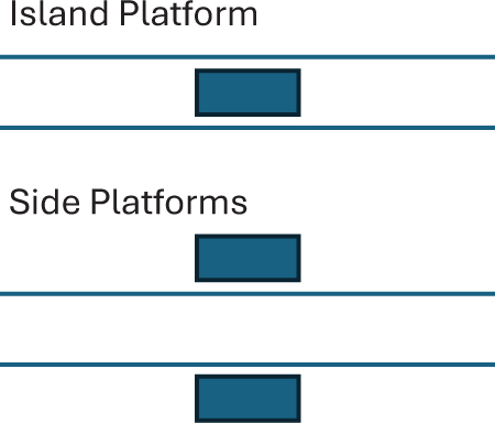
Station capacity depends on the type of regional rail service, whether the service characteristics are uniform or variable, and the stationʼs physical configuration. These operational and physical characteristics apply to existing or new stations and to improvements to an existing station. Station capacity depends in part on the station track and platform configuration and how the platform tracks are used by trains. A simple station on a two-track rail or transit line with through-running operations can have either side platforms or a center island platform, as shown in Exhibit 8-X1. Trains move directionally, follow each other along the line, and dwell at the station without the need to change tracks.
Overall line capacity can be governed by station dwell time. Where dwell times are sufficiently short, and where train performance and train stopping patterns are uniform for all trains using the line, the station capacity can match the overall line capacity and can deliver high-density service. Many examples exist of heavy rail transit that can achieve 2-min headways (30 trains per hour) or better and RRM service that can reach at least 24 trains per hour.
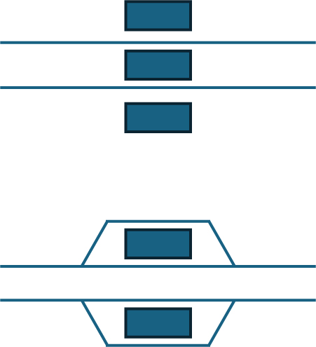
When station dwell times reach a certain point, the stationʼs capacity can be reduced below that of the overall line. Following are potential configurations that can deliver higher capacity where needed:
- Providing separate platform faces for alighting and boarding passengers, which can reduce station dwell times
- Adding a platform track in each direction to enable alternating trains to use different tracks
These configurations are shown in Exhibit 8-X2.
Some stations on rail transit and regional rail lines are configured to permit hybrid operations, with some trains running through and others stopping and turning back. These stations typically are configured to avoid having trains change direction on the main running tracks because these trains require longer dwell times for turning
Long Description.
The diagram presents two station configurations. The first configuration is labeled Island Platform and shows one platform placed between two tracks. The second configuration is labeled Side Platforms and shows two platforms placed on either side of two tracks with nothing between the tracks.
Long Description.
The diagram presents two station configurations. The first configuration shows two tracks with three platforms placed along the tracks, one above, one between, and one below the tracks. The second configuration shows two tracks with platforms on both sides and tracks going from the main tracks, around the platform area, and rejoining the main tracks.
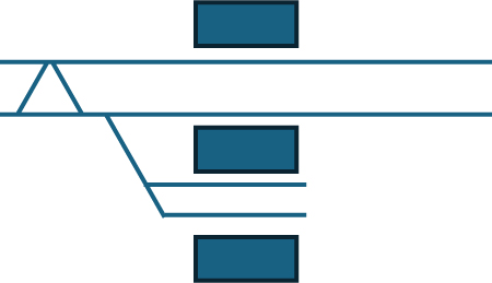
and would run the risk of delaying subsequent trains. Usually, one or two additional tracks and additional platform faces are provided to support both through and turnback operations. If the turnback tracks are on one side of the right-of-way, as shown in Exhibit 8-X3, turnback operations would introduce a head-on conflicting train movement, which reduces overall capacity.
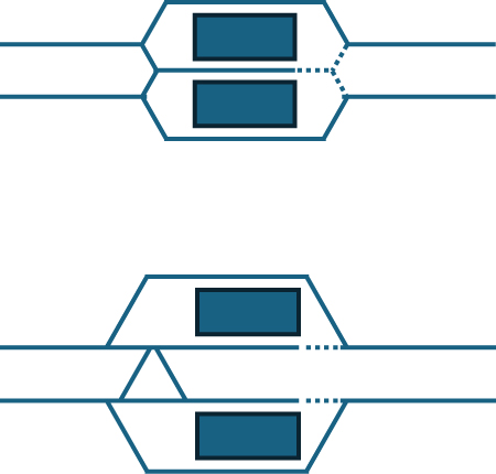
Station configurations with one or two pocket tracks between the main tracks, used for turnback movements, still involve merging conflicts but would eliminate head-on conflicting movements, thereby increasing overall capacity. These types of stations, shown in Exhibit 8-X4, are prevalent on rail transit and some regional rail systems.
Large rail stations in urban centers also can be configured to support through-running. These stations differ from the relatively
Long Description.
The diagram presents a station layout with connected tracks and platforms. Two main tracks run through the station. A branching track connects to a stub-end track. Three platforms are shown, one along the upper track, one along the middle track, and one along the lower stub-end track. The tracks connect through a junction on the left side.
Long Description.
The diagram presents two station configurations with through tracks and pocket tracks. In the first configuration, two main tracks are shown with one pocket track between them and two platforms placed between the tracks. In the second configuration, two main tracks are shown with one pocket track between them and platforms placed on both sides of the tracks. A total of two pocket tracks is shown, one in each configuration.
simple transit or RRM stations in the number of platform tracks provided and the size and complexity of the interlockings on both sides of the station. Two typical through station configurations are used in the United States and internationally, shown in Exhibit 8-X5. The two configurations affect capacity differently:
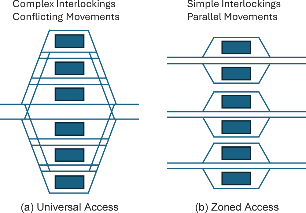
- Universal access. All tracks are accessible from the approach tracks; this configuration is characterized by large, complex interlockings.
- Zoned access. Several smaller stations are side by side, each fed by different sets of approach tracks; this configuration is characterized by smaller interlockings with multiple sets of approach tracks that are grade separated from each other.
Universal access, shown in Exhibit 8-X5(a), treats the station as one entity, with trains dispatched among all available tracks. This configuration can introduce head-on movement conflicts, relatively long running times, and low speeds for train movements through the interlockings. Its capacity can be limiting. Zoned access, illustrated in Exhibit 8-X5(b), is more prevalent in Europe. This configuration carves the station into multiple zones, where trains operate in parallel into and out of the station within each zone, with fewer train movement conflicts and resulting in higher capacity. The interlockings at these stations often involve fewer switches and better track geometry, but they require wide station throats and significant investment in parallel track capacity away from the station itself.
A good U.S. example of a large, center-city station configured for through-running is Philadelphiaʼs 30th Street Station. It has tracks and platforms on two levels, both of which are set up primarily for through-running: the upper level (used by SEPTA Regional Rail trains) and the lower level (used by Amtrak and NJ Transit Atlantic City Line trains).
Several examples also exist of legacy rail stations—both stub-ended and through-running—where a new RRM station has been constructed adjacent to the legacy station to support through-running, metro-style service separate from the more complex operations and wider mix of train types that remain at the older station. The schematics shown in Exhibit 8-X6 illustrate the separate-but-adjacent nature of these station configurations.
Long Description.
The diagram presents two station configurations. The left configuration is labeled Complex Interlockings, Conflicting Movements and shows multiple tracks crossing and connecting to six platforms. The right configuration is labeled Simple Interlockings, Parallel Movements and shows three separate track pairs, each connected to two platforms, with no crossings between the track pairs.


