Low-Level DC Leakage and Fault Currents in Transit Systems: Developing a Prototype for Detection and Mitigation (2025)
Chapter: 3 Findings and Applications

CHAPTER 3
Findings and Applications
Electrical Impedance Modeling of Third-Rail DC Transit System
Before developing a sensor to measure high-frequency impedance and correlating the measurements to leakage currents and faults in the transit system, the researchers developed an analytical impedance model for a generic third-rail system.
As frequency increases, the current in a conductor shifts toward the surface, effectively reducing the cross-sectional area available for conduction (Zhang 2024). This results in increased impedance, affecting the accuracy of current measurements and fault localization. This phenomenon is called “skin effect,” and the researchers have found that it is very prominent for third-rail systems, as the conductor is basically a large metal bar. So, the skin effect plays a critical role in third-rail systems due to the high-frequency signals involved in fault detection.
Details of the alternating current (AC) impedance modeling and its effect related to the applied frequency of injection are described in Appendix A. Based on the researchersʼ modeling, the per-length impedance of the third-rail DC transit system is provided in Table 1, which includes the line AC+DC resistance and the inductance.
Field Measurements at SEPTA Facility to Match with Analytical Impedance Modeling
The UA team conducted field tests at the Southeastern Pennsylvania Transportation Authority (SEPTA) facility. The first visit included impedance measurements through impedance analyzers to correlate analytical models with actual field tests.
The field tests demonstrated the significant AC impedance variation with the applied frequency. Through the tests and postprocessing, the researchers determined distributed AC capacitance values for the network and included them in the analytical impedance modeling.
The revised analytical model consisted of a 600-ft section of third rail, split into 10-ft segments, with a capacitive coupling of approximately 290 picofarads (pF) between the conductor and the return path.
The simulation studies were conducted at different frequencies, measuring the resulting current and phase shift to determine the faults on the third rail at various locations of the 600-ft track. Table 2 presents the fault locations and the impedance variations for the different frequencies used for the injections.
While injecting higher frequencies would require less effort in terms of driver design, the researchers observed that 1 kHz signal injection provided much better detection for faults at different locations on the track.
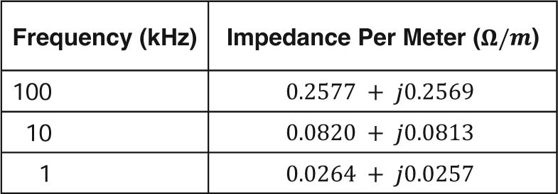
Long Description.
The column headers are Frequency (kilohertz) and Impedance per meter (ohms per meter). The data given in the table are as follows: Row 1: 100 kilohertz; 0.2577 plus j0.2569 (ohms per meter). Row 2: 10 kilohertz; 0.0820 plus j0.0813 (ohms per meter). Row 3: 1 kilohertz; 0.0264 plus j0.0257 (ohms per meter).
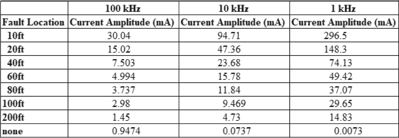
Note: mA = milliamperes.
Long Description.
The first column shows fault locations at different distances in each row of the column: 10 feet (ft), 20 ft, 40 ft, 60 ft, 80 ft, 100 ft, 200 ft, and none, respectively. The second, third, and fourth column headers are 100 kilohertz (kHz), 10 kHz, and 1 kHz, respectively. Those same three columns each show the current amplitude in milliamperes (mA) at the frequency given in the column's header for each of the different fault distances. The data given in the table are as follows: Row 1, 10 ft: 100 kHz: 30.04 mA; 10 kHz: 94.71 mA; 1 kHz: 296.5 mA. Row 2, 20 ft: 100 kHz: 15.02 mA; 10 kHz: 47.36 mA; 1 kHz: 148.3 mA. Row 3, 40 ft: 100 kHz: 7.503 mA; 10 kHz: 23.68 mA; 1 kHz: 74.13 mA. Row 4, 60 ft: 100 kHz: 4.994 mA; 10 kHz: 15.78 mA; 1 kHz: 49.42 mA. Row 5, 80 ft: 100 kHz: 3.737 mA; 10 kHz: 11.84 mA; 1 kHz: 37.07 mA. Row 6, 100 ft: 100 kHz: 2.98 mA; 10 kHz: 9.469 mA; 1 kHz: 29.65 mA. Row 7, 200 ft: 100 kHz: 1.45 mA; 10 kHz: 4.73 mA; 1 kHz: 14.83 mA. Row 8, none: 100 kHz: 0.9474 mA; 10 kHz: 0.0737 mA; 1 kHz: 0.0073 mA.
The frequency of injection was determined based on initial field measurements and analytical modeling. The sensor design was carried out as the next step, which involved electronic, magnetic, and software design, as well as prototyping and laboratory testing.
The system that has been developed consists of a custom impedance sensor, a nano-crystalline circular cut core for current injection, a signal conditioning circuit, and a microcontroller-based processing unit with a graphical user interface (GUI) for real-time monitoring. The unit is capable of developing variable injection frequency starting at 1 kHz.
The detailed design process for the sensor network is provided in Appendix B.

