Low-Level DC Leakage and Fault Currents in Transit Systems: Developing a Prototype for Detection and Mitigation (2025)
Chapter: Appendix B: Sensor Design

APPENDIX B
Sensor Design
Based on the analysis and simulation, the sensor operates by injecting a controlled 1 kHz sinusoidal voltage into the third rail and measuring the resulting impedance variations to identify faults. The system consists of three primary components: the voltage injection unit, the impedance measurement system, and the data processing and communication module.
B.1 Voltage Injection Unit
The voltage injection unit is responsible for introducing a stable and precisely controlled 1 kHz sinusoidal signal into the third rail. This unit is designed to minimize energy loss while ensuring effective signal injection into the rail system. A nano-crystalline circular cut core (Figure B.1) was selected due to its high permeability. These cores serve the purpose of efficiently concentrating magnetic flux, resulting in high permeability. For this reason, power dissipation, which is known as “core losses,” is minimized. Nano-crystalline cores perform well across a wide frequency range, from low to high frequencies, with reduced energy consumption.
For the selected core, the maximum current the core can carry before getting saturated needs to be calculated. By using the core specifications (Table B.1) and the equivalent magnetic circuit model [Figure B.2(b)], the maximum current can be calculated.

Source: https://www.nanoamor.com/nanocrystalline_circular_cut_cores

Long Description.
The two column headers of the table are parameter and value. The data given in the table are as follows: Row 1: parameter: Inner Diameter, r sub 1; value: 115 millimeters (m m). Row 2: parameter: Outer Diameter, r sub 2; value: 140 m m. Row 3: parameter: Depth, w; value: 55 m m. Row 4: parameter: Air gap, l sub g; value: 15 m m. Row 5: parameter: Relative Permeability, μ; value: 30000. Row 6: parameter: Flux density at saturation, B sub sat; value: 1.25 T.

Note: Rc = reluctance of the core; Rg = reluctance of the air gap.
Long Description.
Part A, Injector physical arrangement: A cross-sectional view of a toroidal magnetic core with a central air gap is shown. The core has a width w, radius r, and a small air gap of total length l sub g, split evenly on both sides of the core (each side has a gap of l sub g divided by 2). A wire coil with "N turns" is wound around the core. The 3 D view beside it shows the physical structure of the coil wrapped around the core, with the air gap highlighted. Part B, Equivalent Magnetic Circuit Model: The circuit diagram includes a source labeled 'N i' and a flux path represented by the phi symbol. It consists of four magnetic reluctances: two labeled R sub c and two R sub g, arranged in a loop. The two R sub c and R sub g are connected in a parallel manner.
What follows is the equation for determining the maximum current that needs to be driven. From the equivalent circuits, the magnetic flux density of the core can be expressed as:
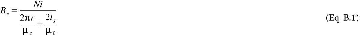
where N is the number of turns of the coil, i is the applied current, r is the radius of the core, lg is the length of the air gap, μc is the permeability of the core, and μ0 is the permeability of the air gap. The maximum current that will make the core saturated can be calculated as:


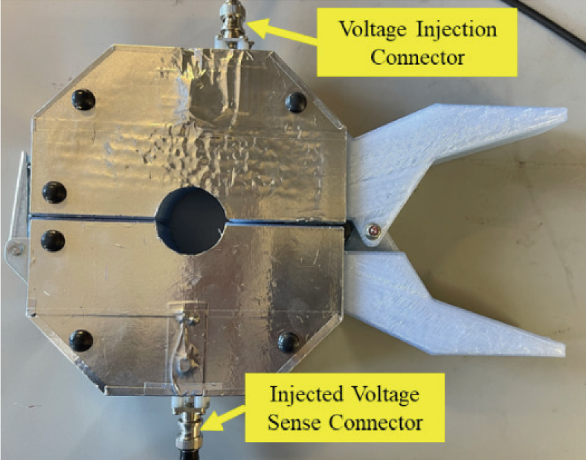
Bsat is the level of Bc when the core is saturated. Using Eq. B.2 and the parameters provided in Table B.1, the maximum current can be calculated as 90A, as the amplifier can supply maximum 3A current, and at 3A current, Bc is 0.05T << Bsat (1.25T). So, the core will not be saturated at the operating current and can perform well as an injector. See Figure B.3 for an example of the voltage injection unit.
Long Description.
The metallic octagonal body of the injection unit consists of two halves with a horizontal gap between them. The voltage injection connector is located on the top part, while the injected voltage sense connector is at the bottom.
B.2 Impedance Measurement System and Data Processing and Communication Module
The block diagram of the sensor system is presented in Figure B.4, which includes the voltage injector, current sensor, signal conditioning unit, and microcontroller.

Note: VT = voltage transformer; CT = current transformer; HF = high frequency; ADC = analog todigital converter; and Rcal = calibration resistor.
Long Description.
The impedance measurement system consists of the sensor board on the left and the Transformers on the right. The sensor board contains a microcontroller connected to an oscillator and high-frequency (HF) amplifier, feeding a voltage injector power winding on a Voltage Transformer (VT). The VT also has a voltage sense winding connected to a voltage sense preamp, followed by signal conditioning that flows back to the microcontroller. Below and connected to the VT, a Current Transformer (CT) is shown with a current sense winding and a current calibration winding in the transformers board, connected to a CT preamp and signal conditioning on the sensor board that also flows back to the microcontroller.
This page intentionally left blank.


