Low-Level DC Leakage and Fault Currents in Transit Systems: Developing a Prototype for Detection and Mitigation (2025)
Chapter: 4 Conclusions and Suggested Research

CHAPTER 4
Conclusions and Suggested Research
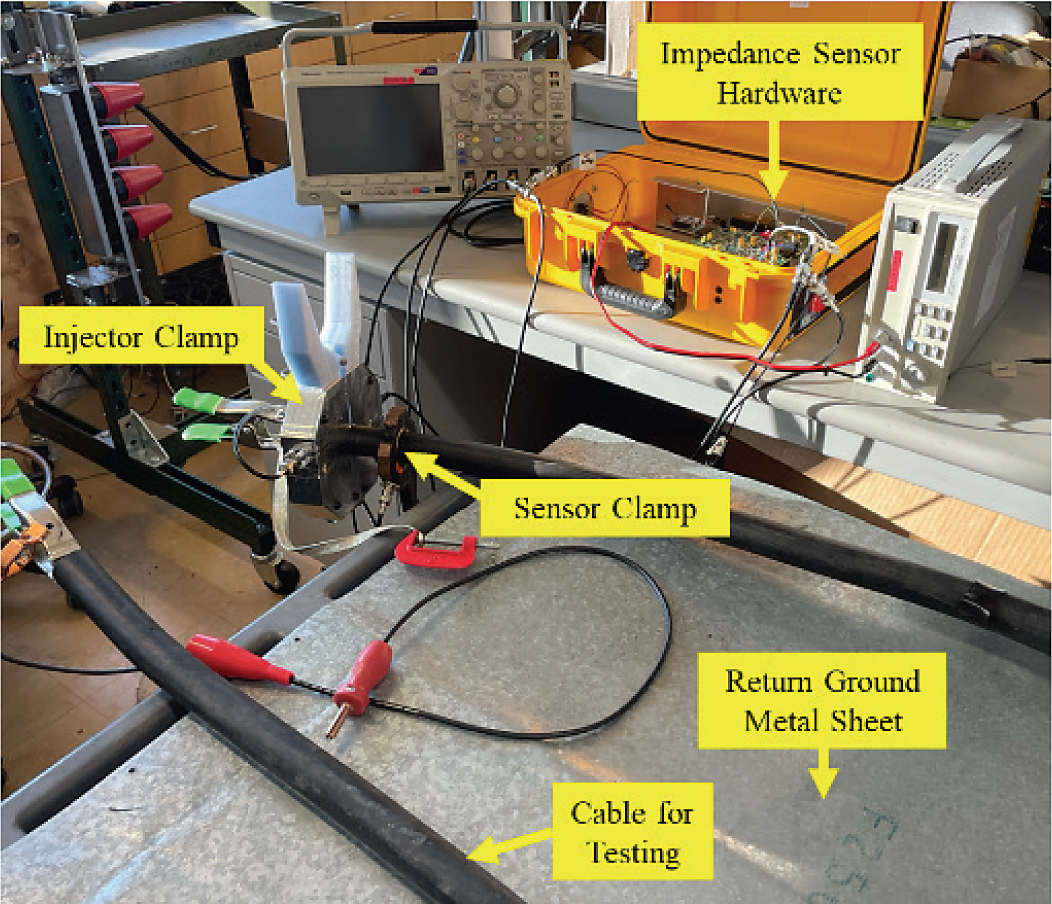
The unit was developed, prototyped, and taken to the SEPTA facility for field testing. The prototype system includes signal injection capability starting at 1 kHz. Figures 3 through 5 present the constructed injector, sensor, and electronics hardware.
Testing Procedure
Field testing was performed on-site, introducing line-to-ground fault conditions. The test involved the following steps:
- Fault Induction:
- Faults were created by connecting the DC positive rail to the ground at predetermined locations along the third rail.
- System Setup:
- The system injected a 1 kHz sinusoidal voltage signal through the test setup.
- The injected voltage and resulting current were measured using the sensing clamps.
- Measurement and Analysis:
- The sensed current and voltage were captured and processed.
- The data was analyzed to evaluate the impedance magnitude as a function of the faultʼs distance from the sensing hardware.
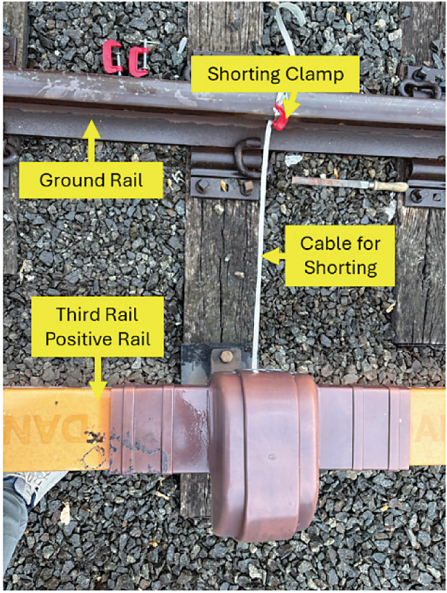
The focus of this test was to determine the systemʼs ability to detect and localize line-to-ground faults (short circuits) at multiple locations along the operational third rail. Figure 6 and Figure 7 present the sensor installation and fault generation on the third rails of the DC transit system at various locations.
Table 3 summarizes the results of field testing conducted at various distances from the sensing equipment. It includes the root-mean-square (RMS) values of the injected voltage and the sensed current, as well as the calculated impedance magnitude. The impedance increases with distance, reflecting the expected resistance and reactance in the third-rail system. These findings demonstrate the systemʼs capability to differentiate fault locations based on impedance characteristics.
Recommendations
- The results from both laboratory and field testing confirm that the impedance-based fault detection system is highly effective for identifying faults. However, high-impedance faults and long-range fault detection require additional improvements, such as improvements to the sensitivity of the current sensors and conditioning circuits.
Long Description.
The impedance sensing test setup is arrayed across two tables. It consists of the following key components: A yellow plastic box of Impedance sensor hardware, a Sensor clamp attached to a cable, a Return ground metal sheet, a Cable for testing, and an Injector clamp that is attached to the cable near to the sensor clamp.

Long Description.
The octagonal body of the injector clamp consists of two halves with a horizontal gap between them. The voltage injection connector is located on the top part, while the injected voltage sense connector is at the bottom.

Long Description.
The clamp has a dark octagonal body with a central circular opening and black handles extending to the right. The body consists of two parts. The current sense connector is located at the top part of the body.

Long Description.
The labeled components include the third rail positive rail at the top, a sensing clamp positioned on a cable leading to the third rail, and an injection clamp below it that is also on the cable. Multiple cables are shown on the ground near the clamps.
Long Description.
The view shows a shorting clamp on a ground rail, which is connected to the third rail positive rail via a cable for shorting.
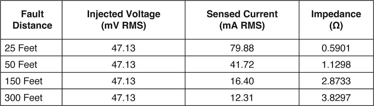
Note: mV = millivolts.
Long Description.
The column headers are Fault Distance, Injected Voltage in millivolts (mV) root mean square (RMS), Sensed Current in milliamperes (mA) RMS, and Impedance (ohms). The data given in the table are as follows: Row 1: 25 feet: 47.13 mVRMS, 79.88 mARMS, 0.5901 ohms. Row 2: 50 feet: 47.13 mVRMS, 41.72 mARMS, 1.1298 ohms. Row 3: 150 feet: 47.13 mVRMS, 16.40 mARMS, 2.8733 ohms. Row 4: 300 feet: 47.13 mVRMS, 12.31 mARMS, 3.8297 ohms.
- Injection of high-frequency signals to the line is initially done through the feeder. Since the feeder was disconnected, it did not provide proper injections to circulate through the complete network. The ideal place for the injection is through the third-rail conductor. Final tests should be done through injection directly to the third rail, which would include some updates to the test structure. The researchersʼ recommendation is to select a larger core that is able to inject current over the third rail.
- The findings indicate that advanced signal-amplification techniques, machine-learning-based fault classification, and real-time noise reduction algorithms should be implemented to enhance system performance further. These enhancements will make the system more reliable, scalable, and effective for large-scale transit network applications.


