Low-Level DC Leakage and Fault Currents in Transit Systems: Developing a Prototype for Detection and Mitigation (2025)
Chapter: Appendix A: Analytical Modeling

APPENDIX A
Analytical Modeling
The third-rail conductorʼs impedance is frequency dependent based on (Eq. A.1). At high-frequency, alternating current (AC) resistance increases due to the skin effect. The skin effect causes the current to concentrate near the surface of the conductors as frequency rises, reducing the effective cross-sectional area available for conduction. So, the skin effect plays a critical role in third-rail systems due to the high-frequency signals involved in fault detection. As frequency increases, the current in a conductor shifts toward the surface, effectively reducing the cross-sectional area available for conduction. This results in increased impedance, affecting the accuracy of current measurements and fault localization. The skin depth, δ, is given by: 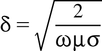 , where μ is the permeability, σ is the conductivity of the material, and ω (ω = 2πf) is the frequency of operation. For a third rail made of carbon steel, the key material properties influencing the skin depth are:
  , width(w) = 0.0254m, and height (h) = 0.05715m. By analyzing the skin effect, it can be determined how impedance varies with frequency (Eq. A.1), allowing for precise modeling and improved fault detection techniques.
The frequency-dependent impedance was calculated using (Eq. A.1) for different frequencies (100 kHz, 10 kHz, 1 kHz), demonstrating a significant increase at higher frequencies.

The model consists of a 600-ft section of third rail, split into 10-ft segments, with a capacitive coupling of approximately 290 picofarads (pF) between the conductor and the return path presented in Figure A.1.

Long Description.
The circuit includes two input ports labeled 'in positive' (1) and 'in negative' (2) connected through series combinations of resistors and inductors. The top path leads to 'out positive' (3), and the bottom to 'out negative' (4). A capacitor is placed between the output lines.
This page intentionally left blank.

