Innovative Materials in Water Resources Infrastructure: Opportunities for the Corps of Engineers (2026)
Chapter: 2 U.S. Army Corps of Engineers Navigation and Flood Risk Management Water Resources Infrastructure
2
U.S. Army Corps of Engineers Navigation and Flood Risk Management Water Resources Infrastructure
The U.S. Army Corps of Engineers (USACE) Civil Works activities and organizational structure shape how innovative materials for water resources infrastructure are researched, developed, applied, and integrated into standard practice. As noted in Chapter 1, this report focuses on operations and maintenance (O&M)1 instead of capital projects, and this chapter introduces USACE’s water resources infrastructure and highlights aspects of the organizational structure most relevant to accelerating the adoption of innovative materials in the O&M phase.
The chapter is divided into two sections. The first section briefly introduces USACE’s extensive water resources infrastructure before examining its inland navigation and flood risk management infrastructure in more detail. The locations, functions, and key infrastructure elements of each system are described, including the basic types of materials that are used in their construction, maintenance, and repair. Data are provided showing that for both systems, aging infrastructure is a challenge that is creating the demand for both more maintenance and repair and more innovative materials, processes, and strategies for developing and deploying them. The structures making up USACE’s navigation locks and dams and flood risk management dams and levees range from comprehensive systems worth billions of dollars to individual subcomponents that can be repaired by local USACE staff (Averitte et al. 2019). This section outlines traditional designs and components and typical materials currently in use, to set the stage for
___________________
1 O&M is a specific USACE term but refers to a broad scope of repair projects.
the discussions of opportunities for deploying innovative materials and technologies in Chapters 4–7.
The second section examines the organizational structure of the USACE Civil Works program, and particularly the functions and responsibilities of the program’s headquarters, division, and district offices. This organizational background is helpful for understanding some of the challenges the program faces in deploying innovative materials, as well as for recognizing opportunities for overcoming them. This section emphasizes the importance of the districts, USACE’s most local geographic organizational units, as well as three key units that facilitate the adoption of new technologies: the Engineer Research and Development Center (ERDC), the Institute for Water Resources (IWR), and the Inland Navigation Design Center (INDC). The peer collaboration and support networks provided by USACE Communities of Practice and Centers of Expertise are also described. Collectively, the USACE innovation ecosystem comprises these units. These institutional sources of innovation within USACE can provide a foundation for the development and eventual widespread adoption of innovative materials. This section also includes USACE’s current strategic priorities for research and development (R&D) of novel materials for water resources infrastructure.
OVERVIEW OF USACE’S WATER RESOURCES INFRASTRUCTURE
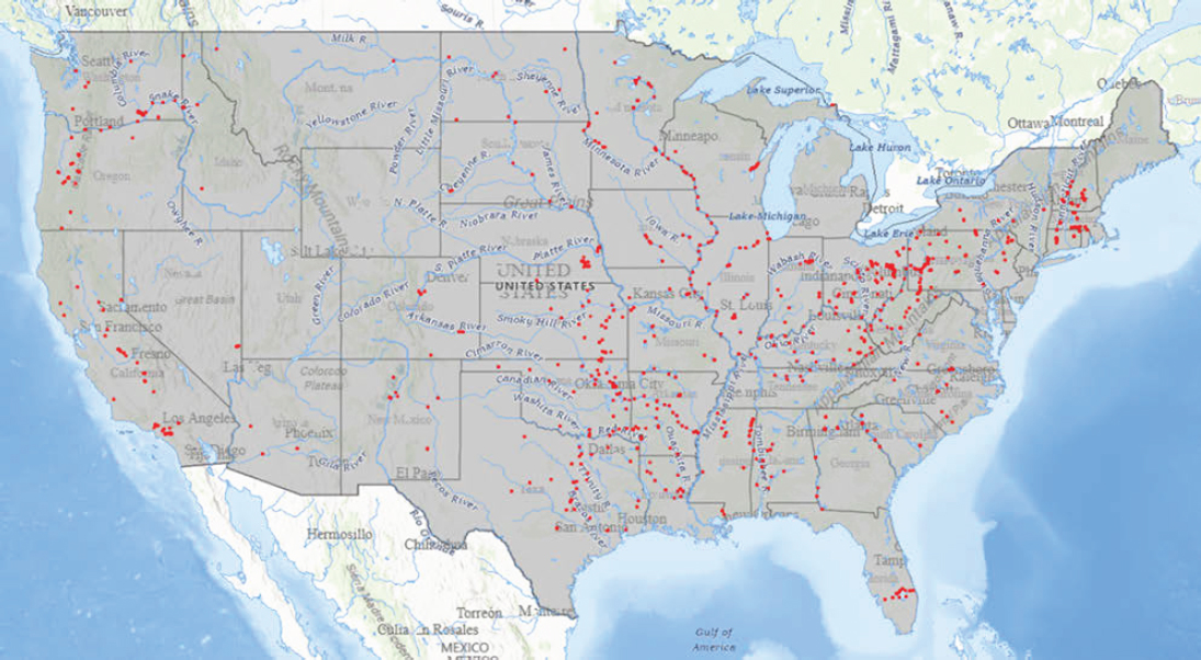
USACE’s navigation infrastructure responsibilities cover the 12,000 miles of waterways that make up the Inland Marine Transportation System, 13,000 miles of coastal channels stretching from Texas to Virginia, and 1,600 miles of deepwater navigation in the Great Lakes Navigation System. USACE’s flood risk management infrastructure is similarly far flung. USACE manages water resources infrastructure across the country, but for historical and logistical reasons, USACE’s dams, locks, and levees are not evenly distributed geographically. Early American population centers were concentrated along the Eastern seaboard and expanded during the early 1800s, an era dominated by waterborne transportation, especially for bulk commodities. USACE established and maintained water navigation routes critical to their economic development (NRC 2013). In addition, there are fewer navigable rivers in the western United States, and much of the Pacific coastline is rugged and not favorable for canal systems.
This section reviews USACE’s inland navigation and flood risk management infrastructure, including the location and age of their structures, the types of structures, and materials used for their components. In particular, the age of both systems poses acute challenges, as there are approximately 9,100 steel structures within the navigation and flood risk management
portfolios currently older than their 50-year design lives.2 On the basis of that 50-year design life, USACE is on the cusp of replacing 260 hydraulic structures per year that were built from 1920 to 1975, which would cost from $1 billion to $2 billion annually.3
Inland Navigation Infrastructure
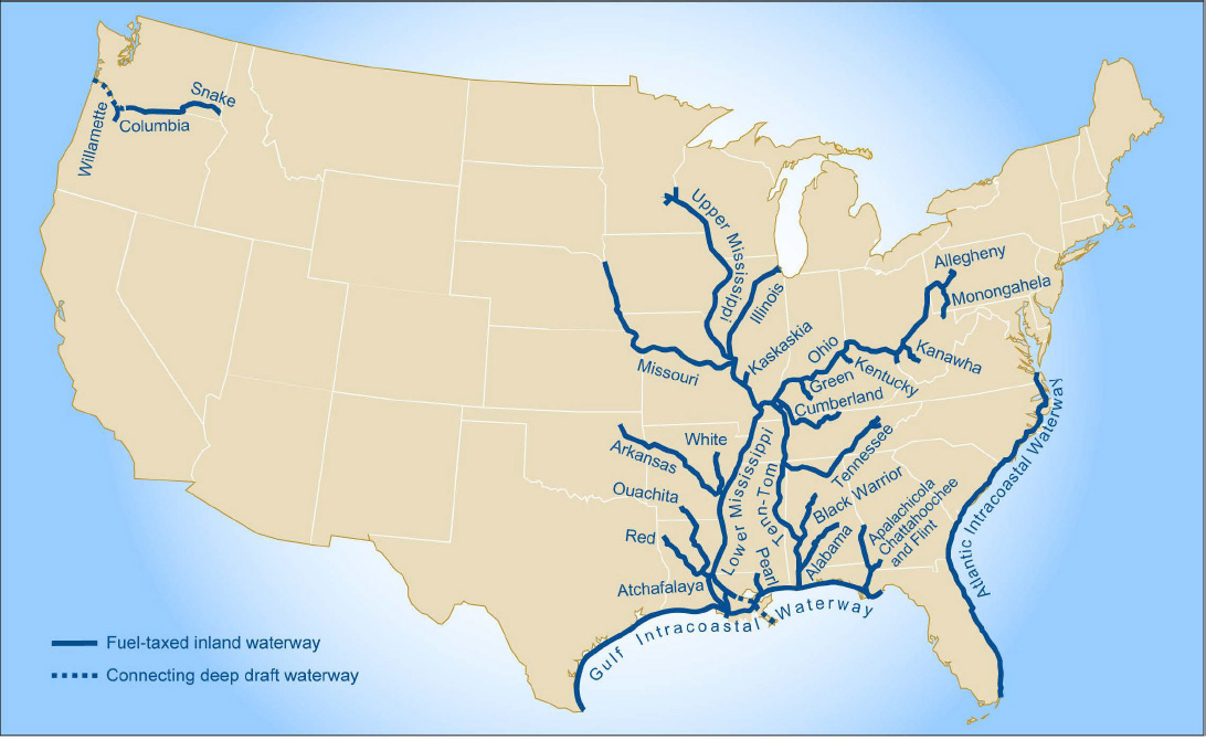
The Inland Marine Transportation System is made up of the commercially navigable rivers in the East Central United States and Pacific Northwest. The system supports barge and tanker traffic carrying bulk cargoes such as grain, coal, aggregate, and petroleum. For example, barges traveling the Mississippi River carry 62% of U.S. grain exports. Water transportation of bulk goods can be more cost-effective than transportation by rail or truck depending on the locations of the shipment and demand (Mazzeno 2024). The major waterways are shown in Figure 2-1.
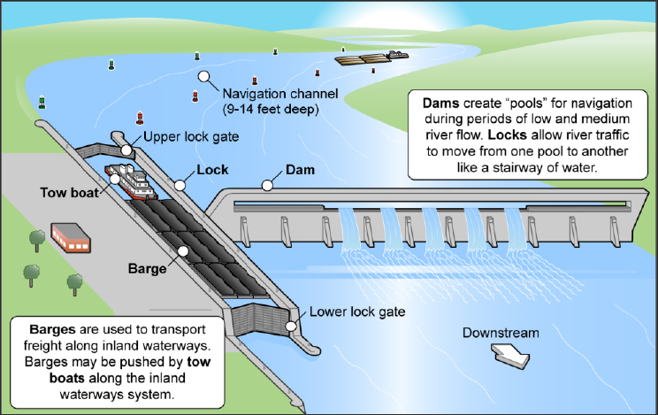
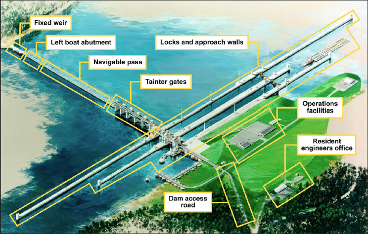
Navigation structures on inland waters include dams and locks. Navigation dams raise or maintain the water level, allowing vessels to pass, while locks enable a vessel to traverse the sudden change in elevation caused by a dam or other topography such as a waterfall. Navigation dams and locks also include various appurtenant structures, such as piers for anchorage of equipment and vessels, flow training walls, and stilling basins. Navigation dams and locks are constructed primarily of rebar-reinforced concrete, but they also contain components made of metal and sometimes other materials. For examples of common dam systems, see Figures 2-2 and 2-3.
USACE’s inland navigation infrastructure includes 209 locks at 167 sites.4 Specific locks can have an outsized impact on certain sectors of the U.S. economy. For example, much of the high-strength steel manufactured in the United States is made with iron ore that travels through the Poe Lock, one of the parallel locks in the Soo Lock system in Sault Ste. Marie, Michigan. If the Poe Lock experienced an unscheduled and prolonged outage, 75% of U.S. high-strength steel production would cease (Dougherty 2024).
The median age of USACE’s navigational structures is 60 years, and thus half are older than the 60-year estimated service life for nonbuilding structures used by the Bureau of Economic Analysis, housed within the U.S. Department of Commerce. However, USACE traditionally uses a minimum service design life of 100 years (USACE 1997). As shown in Figure 2-4, only 5% of its navigation structures are currently older than 100 years, but 28% are between 80 and 100 years old. Over the next 20 years, one-third
___________________
2 USACE presentation to the committee, January 15, 2024.
3 Ibid.
4 “Civil Works: Navigation.” https://www.usace.army.mil/Missions/Civil-Works/Navigation. Accessed May 21, 2025.
SOURCE: GAO 2016.
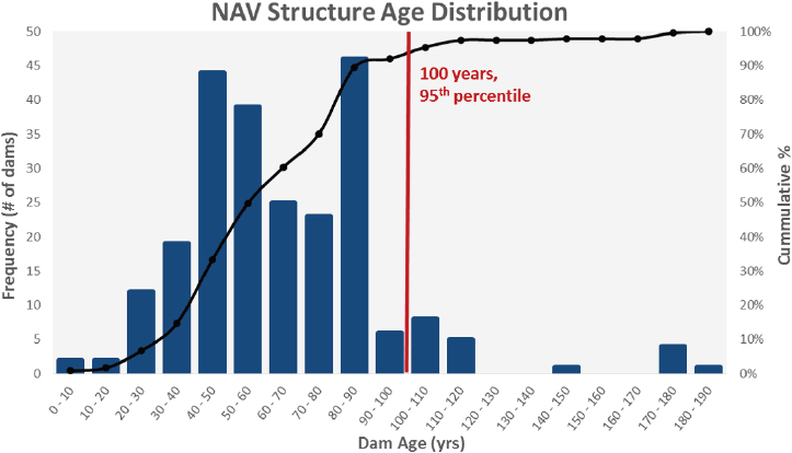
NOTE: According to USACE, these age distributions do not take into account any major rehabilitations or structure replacement.
SOURCE: USACE 2023a.
of USACE’s navigation structures will exceed a 100-year design life (Bennett et al. 2020).
Evolving Users and Needs of Waterways
Users and uses of inland waterways are always evolving, with commercial shipping increasingly relying on larger barges that require more capacity, whereas some waterways now serve primarily recreational purposes. For example, coal producers were historically a primary source of barge traffic on the Allegheny River, but as many have ceased operations in recent decades, the Allegheny 2 Lock now receives only around one commercial vessel each week. Additionally, increased frequency of environmental changes such as flash droughts and flooding have caused constant flux of water levels, altering navigability and infrastructure demands (ASCE 2017). To meet these shifting realities, it is in the best interest of USACE to be continuously responsive, balancing commercial shipping requirements, recreational interests, and environmental stewardship.
Components and Materials Used in Navigation Dams
Although the main body of a navigation dam is concrete, such dams are designed to allow water to pass continuously via a spillway that may have
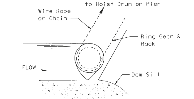
components that use metals. Spillways used for navigation dams are generally one of four types: gated-non-navigable, gated-navigable, fixed crest-overflow, and fixed crest-non-overflow (USACE 1995a). Steel is the most used material for dam gate structures, though stainless steel, aluminum, and composites are possible alternatives. Examples of different types of gate structures include tainter, vertical-lift, wicket, hinged-crest, and roller (see Box 2-1). The tainter gate is a segment of a cylinder mounted on a radial arm that rotates on a trunnion anchored to a navigation dam pier and is the most commonly used radial gate. Vertical-lift gates have rollers at each end and move vertically in guide slots formed in the piers. Wicket gates typically are bottom hinged and lifted into position via a hydraulic cylinder, a mechanical crank, or a gantry-mounted winch. Hinged-crest gates are gates that are hinged at the base, with a variety of means to lift and lower the gate. Finally, the roller gate is a long metal cylinder that is raised and lowered via a chain or cable attached at one end of the cylinder and connected to a hoist. The recently constructed Olmsted Dam on the lower Ohio River (see Figure 2-3) has both wicket gates and tainter gates, while the Montgomery Dam on the Ohio River near Monaca, Pennsylvania, is an example of a navigation dam with vertical-lift gates (see Figure 2-5).
Navigation Locks and Their Components
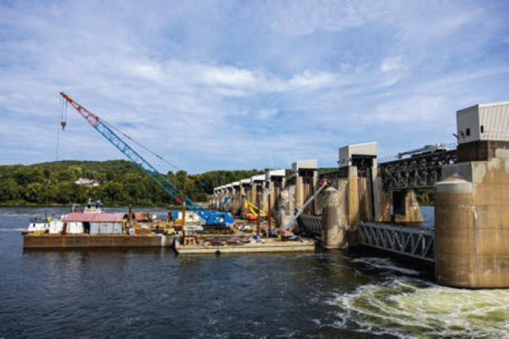
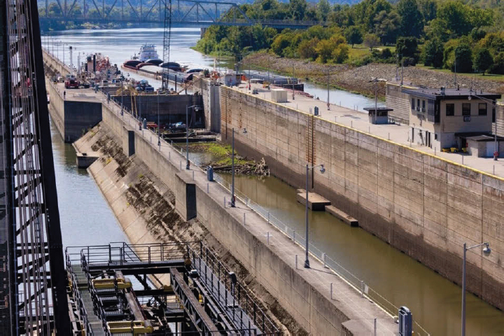
A lock encloses a basin or pool of water, with gates at each end that are operated to lower or raise the water level. The lock structure includes the chamber, lock walls, lock floor, sills, approach walls, flow training structures, piping and utility galleries, and other components (USACE 1995b). The main structural components of locks are made of concrete, usually reinforced with steel, except for the gates, which are typically steel. Figure 2-6 depicts the maintenance and repair work at the Hannibal Lock on the Ohio River in Hannibal, Ohio. The project involves removing and rebuilding four miter gates and replacing eight anchorages and provides a sense of the scale and the multiple structural components of locks.
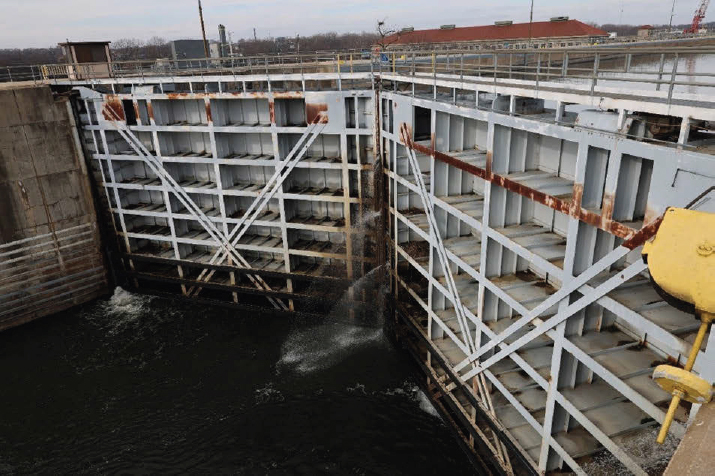
USACE’s locks employ various gate designs. Miter gates, where the two pieces of the gate meet at an angle as shown in Figure 2-7, are common.
Table 2-1 provides a list of some example components and subcomponents of navigation locks taken from the first three levels of a USACE asset management inventory for such systems. The materials associated with each component and subcomponent are provided. There it can be seen that concrete and steel are the dominant material types, though material specifications will vary depending on the component function. Examples of opportunities being considered by USACE, as presented to or observed
BOX 2-1
Types of Navigation Dam Structures
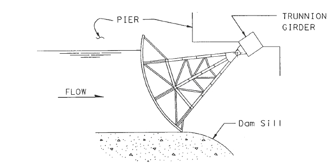
Tainter gate on navigation dam spillway.
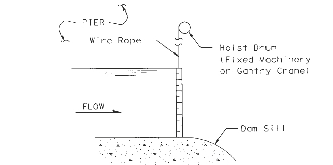
Vertical-lift gate on navigation dam spillway.
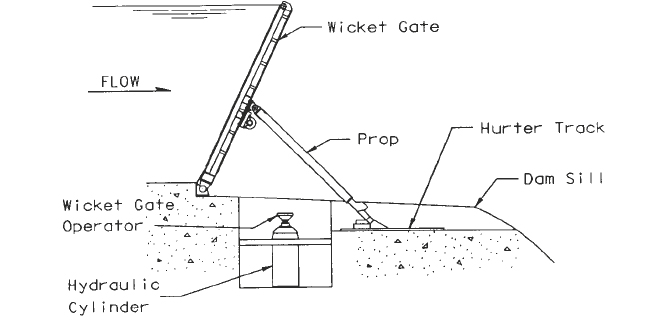
Wicket gate on navigation dam spillway.
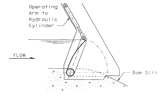
Hinged-crest gate on navigation dam spillway.
Roller gate on navigation dam spillway.
SOURCE: USACE 1995a.
SOURCE: Image courtesy of Michael Sauret, USACE Pittsburgh District.
in use by the committee, for deployment of innovative materials in lock components include 3D-printed powdered-metal tainter-gate arms, ceramic anchorage connections, ultra-high-performance concrete (UHPC) abrasion layers for lock walls, and fiber-reinforced polymer gate fenders.
Corrosion of Metal and Concrete Components
Because navigation dams and locks contain steel, other metals, and concrete that are in continuous contact with moisture and water, corrosion is inevitable. The degradation of metals and concrete through chemical reactions with water and its constituents can lead to significant operational problems and thus is a focus of regular inspections. Corrosion prevention and control are critical maintenance challenges. This is typically done via protective coatings, such as paint. For metals, coatings may be supplemented by cathodic protection systems that apply electric current to the structure’s surface (USACE 2021).
SOURCE: Image courtesy of Andrew Byrne, USACE.
SOURCE: Image courtesy of Emily Helton, USACE.
TABLE 2-1 Examples of Components and Subcomponents for Navigation Locks in the USACE Asset Management Inventory, Including Types of Materials
| System Type | Example Component | Example Subcomponent | Material Type |
|---|---|---|---|
| Lock filling and emptying | Filling and emptying valves | Drain valves | Steel; bronze; other alloys |
| Lock gates and operating machinery | Lock gate anchorages and support features | Lock gate anchorage | Steel |
| Lock gate structure | Quoin blocks | Steel | |
| Fenders | Timber | ||
| Lock structure | Lock walls | Walls | Concrete |
| Navigation aids and auxiliary facilities | Mooring facilities | Mooring cells | Steel sheet piling; concrete filling |
| Navigation aids | Tow haulage | ||
| Steel |
SOURCE: Adapted from committee site visits and USACE presentations.
Flood Risk Management Infrastructure
USACE manages 14,000 miles of levees and 740 dams (see Figure 2-8) as part of its flood risk management mission and many serve multipurpose functions, such as providing hydropower and/or local recreation opportunities. Located in 46 states, these levees, dams, and other mitigation infrastructure are estimated to have prevented more than $100 billion in monetary damages annually between 2010 and 2023 that otherwise would have been lost to floods (USACE 2023b, 2025a).
The median age of USACE’s flood risk infrastructure is 57 years. Although fewer than 5% of these structures are 100 years or older, 22% are in the 70- to 90-year age range (see Figure 2-9). In the next 30 years, more than one in five of USACE’s flood risk management dams will exceed a 100-year design life (USACE n.d.).
Components and Materials Used in Flood Risk Management Dams and Levees
USACE dams for flood risk management need to be sturdy enough to retain significant volumes of water as the reservoirs fill. Dams are of either concrete or earthen construction depending on the topographic conditions (USACE 2004). In addition to the dam’s concrete, soil, and/or rock, the
components of their supporting equipment and facilities use a range of materials.
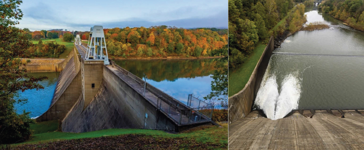
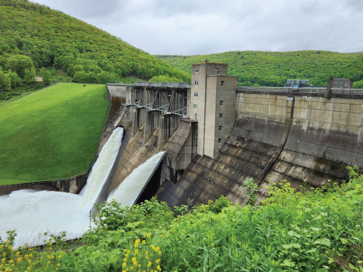
Gravity dams are common flood risk management structures, made of concrete, and feature a triangular cross section constructed across a river valley. The weight of a gravity dam resists the force exerted on it by the water in the reservoir, so gravity dams need to be heavy and constructed on rock foundations (USACE 1995c). They also have drainage galleries near the base of the dam to capture any water seepage through the dam, water inlets on the upstream face, and conduits through the dam for controlled discharge of water downstream. Other appurtenant components include abutments, flow training walls, and stilling basins. The Conemaugh River Dam (see Figure 2-10) is an example of a concrete gravity dam with water discharged at its base into a stilling basin.
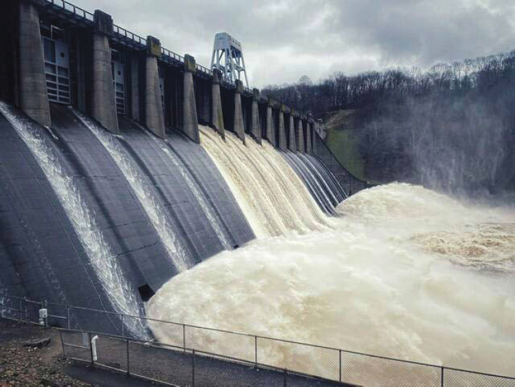
These types of dams can also have spillways or crest gates for management of the reservoir during extreme precipitation conditions (see Figure 2-11). Conduits through gravity dams and gate structures are typically made of steel.
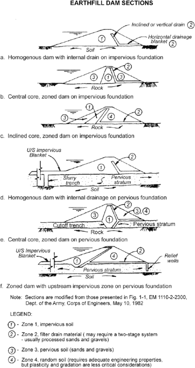
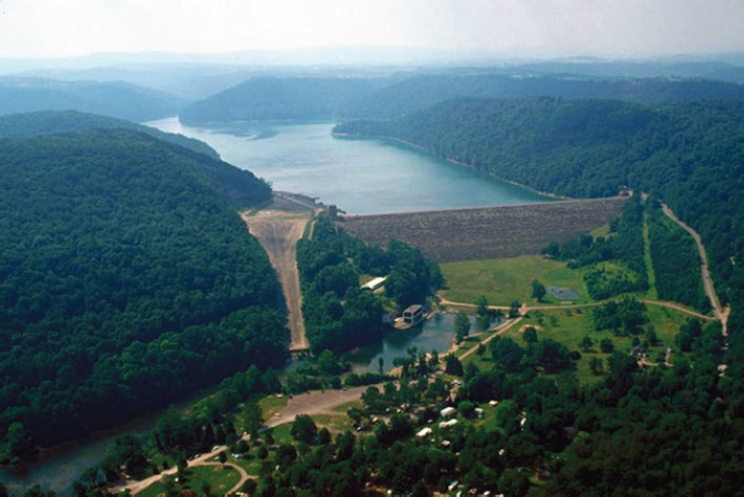
Gravity dams can also be of earthen construction. Some typical cross sections of earthen dams are provided in Figure 2-12, where the types of materials employed are indicated. Geosynthetic materials are often employed in modern earthen dam construction, though these are not indicated in Figure 2-12. An aerial photograph of a large earthen dam constructed and operated by USACE is provided in Figure 2-13. This dam has a single, large-diameter steel discharge pipe and an associated hydroelectric power plant shown on the left side, where the spillway is also evident.
An example of a gravity dam of both earthen and concrete construction is shown in Figure 2-14. As may be seen in the figure, the steel discharge conduits are through the concrete portion of the dam.
Another common flood risk management structure is the earthen levee, an earthen embankment employed along inland rivers to prevent flooding.5 Levees are similar to small earthen dams but differ in important ways. Compared to an earthen dam, a levee’s embankment is designed to become saturated for a shorter period of time. In addition, the need to protect specific facilities or areas often dictates their location, which then circumscribes available foundation conditions and earth materials for construction. Levees are thus generally not designed to the same standards of performance as earthen dams (USACE 2000).
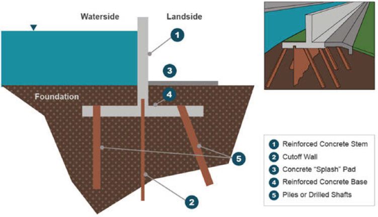
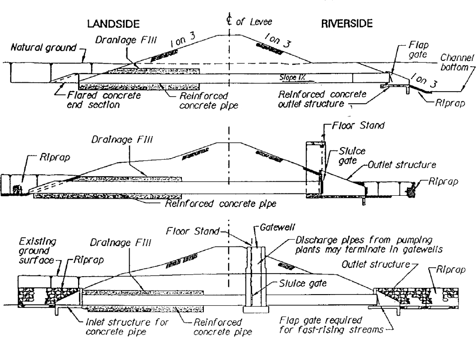
Earthen levees often have other kinds of infrastructure integrated into them for purposes such as protecting embankments, extending levee height through floodwalls (see Figure 2-15), or accommodating pipe crossings
___________________
5 USACE. National Levee Database. https://levees.sec.usace.army.mil. Accessed May 27, 2025.
SOURCE: USACE National Inventory of Dams. https://nid.sec.usace.army.mil/#.

NOTE: According to USACE, these age distributions do not take into account any major rehabilitations or structure replacement.
SOURCE: USACE 2023a.
(see Figure 2-16). The materials used in such infrastructure are typically concrete and steel.
Table 2-2 provides a list of some example components and subcomponents of dams taken from the first three levels of a USACE asset management inventory for such systems. The materials associated with each component and subcomponent are provided. Concrete and steel are the dominant material types, though material specifications will vary depending on the component function. Examples of opportunities being considered by USACE for deployment of innovative materials include UHPC stilling basin surfaces and bio-facilitated grout walls at earthen dams.
CIVIL WORKS OPERATIONS AND GOVERNANCE
USACE’s Civil Works operations encompass navigation and flood risk management, the subjects of this report, and also disaster response, shore protection, hydropower, water supply, recreation, regulation, and environmental restoration. USACE Headquarters is responsible for promulgating policy and securing resources, while the geographic districts are charged with delivering projects, managing the infrastructure, and developing local partnerships. The districts are aggregated into regional divisions that focus
SOURCE: Image courtesy of Michael Sauret, USACE Pittsburgh District.
SOURCE: USACE Pittsburgh District.
SOURCE: USBR 2012.
SOURCE: USACE Pittsburgh District.
on delivering programs, stewarding resources, and regional relationships. Although Civil Works is a distinct mission, it is not necessarily isolated organizationally. Many of the 39 districts that manage Civil Works within the United States and its territories are responsible for civil works and military program missions (Mazzeno 2024).
USACE’s Civil Works mission is also supported by technical policy units responsible for relevant standards and guidance and research and planning functions. Technical policy units are primarily located at the USACE Headquarters level but also within specialized research and technical centers such as ERDC and IWR. USACE’s R&D strategy for Civil Works covers six focus areas:
- Infrastructure;
- Water modeling;
- Crisis preparedness;
- Artificial intelligence, robotics, and data;
- Ecosystems; and
- Sediment management.
SOURCE: Image courtesy of David Dzombak.
Innovative materials for inland navigation and flood risk management structures fit within the infrastructure focus area. USACE defines the purpose and aims of the infrastructure focus area as developing “transformative technologies that enable more cost-effective, resilient and reliable solutions within a changing climate, including ultra-durable and rapid construction materials and processes, models that predict performance and optimize maintenance, and autonomous inspection techniques” (ERDC 2024). The districts, research laboratories, and field operating agencies employ around 95% of Civil Works employees, and USACE uses outside contractors for most of its Civil Works construction and design work (USACE 2024a). USACE Civil Works engineers also participate in internal organizations and conferences such as meetings of the World Association for Waterborne Transport Infrastructure to stay current on innovative material use in hydraulic structures.
This section begins with an overview of the USACE districts and their responsibilities for inland navigation and flood risk management infrastructure and then turns to the role of Headquarters units as well as a number
SOURCE: USACE and FEMA 2024.
of specialized units for water resources whose remit includes innovative materials.
District Operations
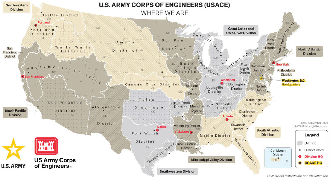
USACE districts function semi-autonomously: most day-to-day decision making and project management responsibilities for inland navigation and flood risk management are delegated to the individual districts to address local needs efficiently.6 Districts build and operate projects and conduct studies with funding from the federal government, nonfederal sponsors such as state or local governments, or a combination of sources. Districts are the front line of stakeholder engagement for USACE Civil Works. As an example, Box 2-2 provides a brief introduction to the Philadelphia District.
District boundaries generally follow the watersheds of major rivers (see Figure 2-17), and the U.S.-based district boundaries have been mostly static since 1950.7 However, USACE has the flexibility to adjust to changing conditions and needs, such as the creation of a new Caribbean District in 2024 to better focus on water resources issues in Puerto Rico and the Virgin Islands (USACE South Atlantic Division 2024).
___________________
6 USACE presentation to the committee, August 29, 2024.
7 “USACE District Locations.” https://www.usace.army.mil/Missions/Locations. Accessed February 7, 2025. For more on USACE’s management of watersheds, refer to USACE (n.d.).
SOURCE: USACE 2000.
TABLE 2-2 Examples of Components and Subcomponents for Dams in the USACE Asset Management Inventory, Including Types of Materials
| System Type | Example Component | Example Subcomponent | Material Type |
|---|---|---|---|
| Dam gates and operating machinery | Dam gate anchorages and support structures | Foundation system | Concrete |
| Drainage System | Steel | ||
| Dam structures | Dam gate structures | Dam gates | Steel |
| Pier dams | Piers | Concrete | |
| Dam spillway | Spillway dissipators | Concrete | |
| Miscellaneous dam features | Work platforms | Steel | |
| Walkways | Concrete |
SOURCE: Adapted from committee site visits and USACE presentations.
BOX 2-2
USACE’S Philadelphia District
The Philadelphia District is responsible for the Delaware River Basin and adjacent Atlantic Coast and covers 15,000 square miles spread across parts of five states. The district maintains more than 550 miles of navigable channels and five highway bridges. After flooding in 1955 that resulted in 90 deaths, the district constructed five earthen dams that it maintains in eastern Pennsylvania. The district is also responsible for construction and installations at Dover Air Force Base and other military facilities.
The following is a partial list of current major USACE projects in the Philadelphia District in fiscal year 2024:
- Delaware River, Philadelphia to the Sea Project ($21.95 million)
- Francis E. Walter Dam Re-Evaluation Study ($0.35 million)
- DuPont Chambers Works Formerly Utilized Sites Remedial Action Program ($43.15 million)
- Chesapeake and Delaware Canal and Chesapeake City Bridge ($9.65 million)
- Absecon Inlet Navigation Project ($3.645 million)
- Cold Spring Inlet Navigation Project ($1.318 million)
SOURCE: USACE 2024b.
NOTE: HQ = Headquarters.
SOURCE: “USACE District Locations.” https://www.usace.army.mil/Missions/Locations. Accessed February 7, 2025.
The decision-making authority of districts aligns with the realities of managing diverse water infrastructure projects and varying levels of investment and cooperation from state governments and other stakeholders. However, this semi-autonomous system can also create silos that impede adopting innovations. For example, their expertise often reflects the needs of their local waterway conditions, meaning that district staff have differing tolerances of risk for using innovative materials.8 That being said, the districts and district staff are often the front line for engagement with waterway stakeholders and waterway users.9 Districts also operate with limited funds and may work with a limited number of contractors who have varying experience with innovative materials. These conditions can lead to a cultural bias toward traditional materials and technologies and an attitude toward innovation that amounts to “everyone wants to be second.”10 As is discussed in more detail in the chapter featuring asset management, for some materials such as UHPC, the higher upfront material and installation costs can deter utilization, despite the proven long-term benefits.11
Collaboration Networks and Support
District engineers can also collaborate with each other through Communities of Practice (CoPs) and Centers of Expertise (CXs). These peer networks, which span organizational units, are designed to “provide an inventory of specialized knowledge and skills within USACE that can furnish beneficial and expert assistance to all USACE elements”12 focused on a particular problem area. For example, these are the key responsibilities of the Navigation CX:
- Support design, maintenance, and modernization of
- Navigation locks and dams,
- Coastal ports and harbors, and
- Inland waterway systems.
- Provide expertise in
- Hydrodynamics and sediment transport,
- Channel design and maintenance,
- Navigation structures and systems,
___________________
8 ERDC presentation to the committee, November 21, 2024.
9 For an example of a local advocacy group, see the Warrior-Tombigbee Waterway Association. https://www.warriortombigbee.com.
10 ERDC presentation to the committee, August 29, 2024.
11 USACE Concrete Materials Regional Technical Specialist presentation to the committee, October 21, 2024.
12 ERDC. “About the Centers of Expertise.” https://mrsi.erdc.dren.mil/coe. Accessed June 3, 2025.
-
- Vessel traffic simulation and analysis, and
- Environmental impacts of navigation projects.
CoPs and CXs facilitate knowledge sharing among people with a common interest. CXs are distributed throughout the USACE organizational structure at different levels and aim to serve as a resource for specialized technical knowledge.
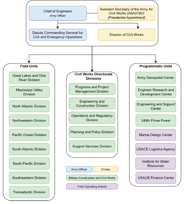
Civil Works Directorate
The functional areas required for USACE’s Civil Works mission are also represented at the headquarters level in the organizational units operating in the Civil Works Directorate (as shown in Figure 2-18). Although its Engineering and Construction, Operations, and Planning and Policy divisions are the most relevant to this report, other functional areas include emergency operations, navigation, recreation, and the regulatory program that reviews construction in U.S. waters including wetlands.
Engineering and Construction, as part of its mission to direct the technical aspects of engineering and construction management, develops policy, guidance, and standards, including to integrate new technologies and materials and to implement value engineering. Engineering and Construction also serves USACE’s military programs.13 USACE’s Planning and Policy unit and Project Planning team develop planning-related policies including for how to develop and prioritize projects for implementation (see, e.g., USACE 2023c).
While most of the guidelines related to innovative materials come from Engineering and Construction leadership, other Civil Works headquarters offices and CXs also develop guidance, creating a complex R&D environment. Descriptions of key R&D units are provided below.
U.S. Army Engineer Research and Development Center
The U.S. Army ERDC, a unit of USACE Headquarters, conducts R&D and provides expertise to the districts. As of May 2025, ERDC has a staff of approximately 2,600 federal employees and contractors and managed an annual research program that exceeded $2 billion at seven laboratories in four states, including at its headquarters in Vicksburg, Mississippi. Water resources and civil works are one of its five major research areas.14 ERDC’s
___________________
13 USACE. “Engineering and Construction.” https://www.usace.army.mil/Missions/Civil-Works/Engineering-and-Construction. Accessed May 30, 2025.
14 USACE ERDC. “About Us.” https://www.erdc.usace.army.mil/About. Accessed May 27, 2025.
SOURCE: Adapted from USACE 2024a. “USACE District Locations.” https://www.usace.army.mil/Missions/Locations.
Civil Works R&D is not an isolated research area: innovations developed as part of ERDC’s military programs are also adapted to Civil Works’ needs (USACE 2024c).
ERDC coordinates with the districts to establish R&D priorities, and the subsequent Civil Works R&D strategy is publicly available to inform potential partners in academia, industry, and other federal agencies. Most recently updated in April 2025, the strategy includes nine “targeted strategic capabilities” as listed in Box 2-3. Several of these areas relate to using
BOX 2-3
ERDC’s Civil Works Infrastructure Priorities
In April 2025, the Engineer Research and Development Center (ERDC) released an updated strategy for its Civil Works research and development “to address the most critical mission-delivery gaps.” Its targeted strategic capabilities for infrastructure are the following:
- Robotic inspection and repair;
- Advanced manufacturing;
- Sensor and testing methods for structures, dams, and levees;
- Novel and sustainable materials;
- Natural disaster damage prediction and mitigation;
- Innovative designs and prototyping for infrastructure life extension;
- Innovations in hydropower;
- Advanced coatings and corrosion mitigation; and
- Systems engineering for optimal maintenance
SOURCE: USACE 2025b.
innovative materials and technologies in inland navigation or flood risk management infrastructure. For novel and sustainable materials, ERDC plans to “examine and pilot innovative construction materials, such as fiber-reinforced polymer composites, steel, and wood, to create alternatives for new and existing structures,” including investigating the resilience of operations and supply chains. The strategy includes approaches for deploying research in practical applications. Novel materials are also part of creating innovative designs and prototyping for extending infrastructure life. In addition, ERDC is prioritizing advanced manufacturing techniques to replace structural components and researching new alternatives for coatings and corrosion mitigation technologies (USACE 2025b).
Institute for Water Resources
USACE’s IWR supports the Civil Works program through “forward-looking analyses, cutting-edge methodologies, and innovative tools.” IWR operates six centers: the Water Resources Center, Hydrologic Engineering Center, Navigation & Civil Works Decision Support Center, Waterborne Commerce Statistics Center, Collaboration and Public Participation Center of Expertise, and Risk Management Center. IWR serves Headquarters as well as the divisions and districts and is responsible for tracking emerging water resources trends and issues and for developing and implementing
state-of-the-art methods for water resources planning, engineering, and operations. For example, IWR convened managers from throughout the Corps to share experiences and develop best practices for asset management (e.g., IWR 2013). IWR assists USACE Headquarters with development of technical guidance when requested. IWR also provides USACE’s CX for dam and levee safety.15 Additionally, one of IWR’s technical centers is the Waterborne Commerce Statistics Center (WCSC), whose primary function is to collect, process, distribute, and archive vessel trip and cargo data.16
Inland Navigation Design Center
INDC is a “mandatory” CX housed within the Mississippi Valley Division and located in the Rock Island District and the Pittsburgh District. As a mandatory CX, INDC must be involved when a district engages in certain activities related to building new or rehabilitating navigation dams and locks. District personnel also engage INDC regularly as a technical resource for O&M and planning questions that arise. INDC’s goals include to strengthen technical competency and to standardize lock and dam infrastructure and components. To fulfill this latter goal, INDC is to “lead a coordinated effort to provide common engineering and design services that result in common lock and dam infrastructure and components to reduce life-cycle costs and increase reliability, safety, and consistency.” This effort is to include “the use of tested and proven composites, and other innovations, to reduce life-cycle O&M costs” (USACE 2022). Thus, INDC works to harmonize approaches to engineering design and decision making regarding lock and dam infrastructure. INDC also conducts investigations and recommends R&D needs to USACE Headquarters and ERDC.17
SUMMARY
- Districts have significant autonomous decision-making authority in managing their infrastructure.
- Districts submit their maintenance needs as part of O&M requests, Headquarters decides what will be done, and districts decide how it will be done and execute the projects.
___________________
15 USACE. “IWR: Mission and Values.” https://www.iwr.usace.army.mil/About/Mission-and-Vision. Accessed May 30, 2025.
16 USACE. “Waterborne Commerce Statistics Center (WCSC).” https://www.iwr.usace.army.mil/About/Technical-Centers/WCSC-Waterborne-Commerce-Statistics-Center. Accessed August 14, 2025.
17 USACE. “Inland Navigation Design Center—Mandatory Center of Expertise.” https://www.mvr.usace.army.mil/about/offices/inland-navigation-design-center-indc. Accessed May 30, 2025.
- O&M maintenance repair, rehabilitation, and component replacement projects present opportunities for introducing innovative materials.
- Districts, through their stakeholders and contractors, are primary sources of information on development needs for innovative materials.
- Districts are on the front line of user community and community stakeholder engagement.
- Much of the inland navigation and flood risk management infrastructure was built 70–100 years ago and is beyond design life and expensive to maintain.
- Commercial uses for inland navigation evolve. Some facilities no longer have commercial use. O&M budgets are stretched thin to maintain the large and varying infrastructure with varying levels of use.
- Inland navigation and flood risk management infrastructure are subject to the challenges of changing environmental, water supply, and operational demands (e.g., barge size).
- Inland navigation and flood risk management infrastructure involves thousands of individual components.
- Many components are one of a kind and many have reached, or surpassed, their intended lifespan.
- ERDC identifies research needs through consultation with districts.
- ERDC personnel have state-of-the-art knowledge about innovative materials and are actively working to get them into practice.
- ERDC collaborates with and relies on the districts for implementation of innovative technologies.
- USACE Headquarters develops policy, guidance, and standards that have an important role in materials used in water resources infrastructure
- The USACE CXs, IWR, and INDC help ERDC, USACE Headquarters, and districts to advance innovative technologies and materials.
REFERENCES
ASCE (American Society of Civil Engineers). 2017. “Inland Waterways Report Card 2025.” January 17. https://infrastructurereportcard.org/cat-item/inland-waterways-infrastructure.
Averitte, S. A., B. Bell, and K. McLaughlin. 2019. “Olmsted Dam and Making Modern America.” AECOM. https://infrastructure.aecom.com/2019/accelerating-delivery-olmsted-dam.
Bennett, J., R. Kornfeld, D. Sichel, and D. Wasshausen. 2020. “Measuring Infrastructure in BEA’s National Economic Accounts.” Working Paper. National Bureau of Economic Research, June. https://doi.org/10.3386/w27446.
Dougherty, C. 2024. “Implementation of Large-Scale Metal Additive (3D Printed) Component at Soo Lock.” Presentation to the committee, October 30.
ERDC (Engineer Research and Development Center). 2024. “Civil Works R&D Value to the Nation: 2024 Edition.” Brochure. U.S. Army Corps of Engineering. https://dx.doi.org/10.21079/11681/48613.
GAO (Government Accountability Office). 2016. “Inland Waterways Fuel Tax: Additional Data Could Enhance IRS’s Efforts to Ensure Taxpayer Compliance” (GAO-16-682). https://www.gao.gov/assets/gao-16-682.pdf.
GAO. 2017. “Army Corps of Engineers: Factors Contributing to Cost Increases and Schedule Delays in the Olmsted Locks and Dam Project” (GAO-17-147). https://www.gao.gov/assets/gao-17-147.pdf.
IWR (Institute for Water Resources). 2013. “Best Practices in Asset Management” (2013-R-08). U.S. Army Corps of Engineers.
Mazzeno, W. P. 2024. “USACE Chicago District Overview.” Presented at the PIANC-USA General Meeting, September 25. https://pianc.us/attend-our-2024-general-meeting.
NRC (National Research Council). 2013. Corps of Engineers Water Resources Infrastructure: Deterioration, Investment, or Divestment? Washington, DC: The National Academies Press. https://doi.org/10.17226/13508.
USACE (U.S. Army Corps of Engineers). n.d. “Water Resources: Watersheds.” Value to the Nation: Civil Works. https://www.iwr.usace.army.mil/Missions/Value-to-the-Nation/WR-Watersheds. Accessed May 28, 2025.
USACE. 1995a. Planning and Design of Navigation Dams (Engineer Manual 1110-2-2607). https://www.publications.usace.army.mil/Portals/76/Publications/EngineerManuals/EM_1110-2-2607.pdf.
USACE. 1995b. Planning and Design of Navigation Locks (Engineer Manual 1110-2-2602). https://www.publications.usace.army.mil/Portals/76/Publications/EngineerManuals/EM_1110-2-2602.pdf.
USACE. 1995c. Gravity Dam Design (Engineer Manual 1110-2-2200). https://www.publications.usace.army.mil/portals/76/publications/engineermanuals/em_1110-2-2200.pdf.
USACE 1997. “Life Cycle Design and Performance” (Engineer Regulation 1110-2-8159), October 31. https://www.publications.usace.army.mil/Portals/76/Publications/EngineerRegulations/ER_1110-2-8159.pdf.
USACE. 2000. Design and Construction of Levees (Engineer Manual 1110-2-1913). https://www.publications.usace.army.mil/portals/76/publications/engineermanuals/em_1110-2-1913.pdf.
USACE. 2004. General Design and Construction Considerations for Earth and Rock-Fill Dams (Engineer Manual 1110-2-2300). https://www.publications.usace.army.mil/portals/76/publications/engineermanuals/em_1110-2-2300.pdf.
USACE. 2021. Cathodic Protection Systems for Civil Works Structures (Engineer Manual 1110-2-2704). https://www.publications.usace.army.mil/Portals/76/Users/182/86/2486/11EM_1110-2-2704%20(003).pdf.
USACE. 2022. “Policy, Roles, and Responsibilities for the Inland Navigation Design Center Mandatory Center of Expertise” (Engineer Regulation 1110-1-8168). https://www.publications.usace.army.mil/Portals/76/Users/182/86/2486/ER_1110-1-8168.pdf?ver=0LVnBonlM5GQH764UYj2eQ%3d%3d.
USACE. 2023a. “Infrastructure Age.” Value to the Nation: Capital Stock Infrastructure Age. https://www.iwr.usace.army.mil/Missions/Value-to-the-Nation/Fast-Facts/Capital-Stock/Infrastructure-Age. Accessed May 23, 2025.
USACE. 2023b. “USACE Flood Risk Management Data 2023 National Report.” Value to the Nation. https://usace.contentdm.oclc.org/utils/getfile/collection/p16021coll2/id/14665.
USACE. 2023c. “Policy for Conducting Civil Works Planning Studies” (Engineer Regulation 1105-2–103). https://www.publications.usace.army.mil/Portals/76/ER%201105-2-103_7Nov2023.pdf.
USACE. 2024a. Fiscal Year 2024 United States Army Corps of Engineers Agency Financial Report—Civil Works. https://www.publications.usace.army.mil/Portals/76/FY%2024%20Civil%20Works%20Annual%20Financial%20Report.pdf.
USACE. 2024b. “Congressional Briefing Book: Philadelphia District.” April. https://www.nap.usace.army.mil/Portals/39/docs/Civil/Factsheets/NEW-2024-Congressional-Briefing-Draft-April-1-2024-Update%20(002).pdf.
USACE. 2024c. “Infrastructure Innovation: New Poe Lock Arrestor Arm Is the Largest U.S. Civil Works Component Produced by 3D Printer.” April 1. https://www.erdc.usace.army.mil/Media/News-Stories/Article/3726876/infrastructure-innovation-new-poe-lock-arrestor-arm-is-the-largest-us-civil-wor.
USACE. 2025a. “Value to the Nation: Flood Risk.” Value to the Nation: Civil Works FY 2024. https://www.iwr.usace.army.mil/Missions/Value-to-the-Nation/Flood-Risk.
USACE. 2025b. “A Blueprint for U.S. Army Corps of Engineers Civil Works Strategic Research and Development.” https://media.defense.gov/2025/May/13/2003712062/-1/-1/0/CW%20STRATEGY%20MAY%202025.PDF.
USACE and FEMA (Federal Emergency Management Agency). 2024. “Understanding Levee Fundamentals.” In National Levee Safety Guidelines. https://mmc.sec.usace.army.mil/NLSP_website/NLSG_Chapter_2_Understanding_Levee_Fundamental_DRAFT.pdf.
USACE South Atlantic Division. 2024. “USACE Establishes an Enduring District in the Caribbean Region with Headquarters in Puerto.” https://www.sad.usace.army.mil/Media/News-Releases/Article/3854869/usace-establishes-an-enduring-district-in-the-caribbean-region-with-headquarter.
USBR (U.S. Bureau of Reclamation). 2012. “Design Standards No. 13: Embankment Dams.” U.S. Department of the Interior. https://www.usbr.gov/tsc/techreferences/designstandards-datacollectionguides/finalds-pdfs/DS13-2.pdf.
This page intentionally left blank.


