Technologies and Practices for Plugging and Remediating Orphan Oil and Gas Wells (2026)
Chapter: 3 How a Well Is Plugged and Plugged Well Failures
3
How a Well Is Plugged and Plugged Well Failures
The primary goals of wellbore plugging and abandonment are protection of usable water sources, isolation of hydrocarbon-bearing or water injection intervals, and prevention of leakage to the surface and unintended cross flow (API 2021). An orphan well’s original construction, age, and current integrity will impact the effectiveness of the plugging design. Key areas of planning include finding as much information as possible about the well, understanding the surrounding geologic conditions, and determining barrier objectives and requirements and the appropriate equipment and materials. Well logging is used to identify the well’s construction details, verify its integrity, and locate key depths for setting cement plugs. Because many orphan wells lack accurate historical records, logging serves as an investigative tool before and during the abandonment process to ensure the well is sealed permanently and safely (see Appendix D).
This chapter describes how wells are plugged, including best practices and industry standards for important plugging elements, such as well barrier considerations, geologic factors, materials, equipment, processes, and barrier verification considerations. The chapter also describes processes for determining the well’s condition, such as configuration and integrity, and factors involved in plugged well failures. In order to achieve the objectives of well plugging for long-term and permanent abandonment, key factors must be considered. These include protecting usable water resources, isolating hydrocarbon-bearing or water injection intervals, preventing leakage of chemicals and gases to the surface, and preventing unintended cross flow—all support protection of public health and safety and the environment. Each of the planning aspects discussed is critical to the effectiveness of a plugging operation and, accordingly, constitutes a potential point of failure.
HOW WELLS ARE PLUGGED
Oil and gas wells are plugged by placing barriers1—such as cement plugs, mechanical plugs, and cement—in the wellbore at varying depths to permanently seal off the oil and gas reservoirs, isolate zones behind casing, and prevent fluid migration. Plugging wells is generally effective in reducing leaks and emissions (Kang et al. 2016; Raimi et al. 2021; Wisen et al. 2020). When plugged wells do continue to emit methane (the most closely monitored gas in the context of plugged wells), they emit less than unplugged wells. For example, a 2016 study of wells in four basins across the United States found methane emissions from plugged wells to be significantly less than from unplugged wells (Townsend-Small et al. 2016), and studies in West Virginia and Pennsylvania found the same (Kang et al. 2019; Riddick et al. 2019). Hydrogen sulfide leakage is less studied but has been found to be strongly correlated with methane emissions (El Hachem and Kang 2022).
An overview of the plugging process follows:
- After the plan is developed, operations begin to remove any obstructions in the well and repair or remove damaged casing.
- A workover fluid is placed in the well to provide a hydrostatic pressure column to prevent reservoir fluid influx and stabilize the well.
- The well needs to be properly conditioned for optimal barrier placement. This can be accomplished by running wellbore cleaning tools, such as brushes and/or scrapers, to mechanically clean tubular walls prior to setting barriers and circulating specially formulated fluids that include surfactants or other chemicals designed to clean tubular walls of residual hydrocarbon, drilling mud, solids, scale, or other deposits to improve cement adhesion and barrier sealability.
- After the barriers are placed, the well is permanently sealed, remaining equipment and contaminants are removed, and surface restoration can begin.
There are any number of potential leak paths through parts of a well (Figure 3-1). Ideally, the plugging plan will consider barrier design, materials, and placement in terms of maximum durability, the best match for surrounding geologic conditions, and regulatory requirements.
Well Barrier Considerations
The American Petroleum Institute states that a barrier, “if properly installed, contributes to the total system reliability by preventing liquid or gas flow” (API 2021, p. 3). The materials and barrier selected “shall be qualified to demonstrate they will retain integrity in the downhole environment to which they are reasonably expected to be exposed” (ISO 2017, p. 76). And, “since the initial geologic state was a continuous seal, well abandonment is typically performed by creating a continuous barrier across
___________________
1 For definitions of barrier and plug, see the Glossary in Appendix B.
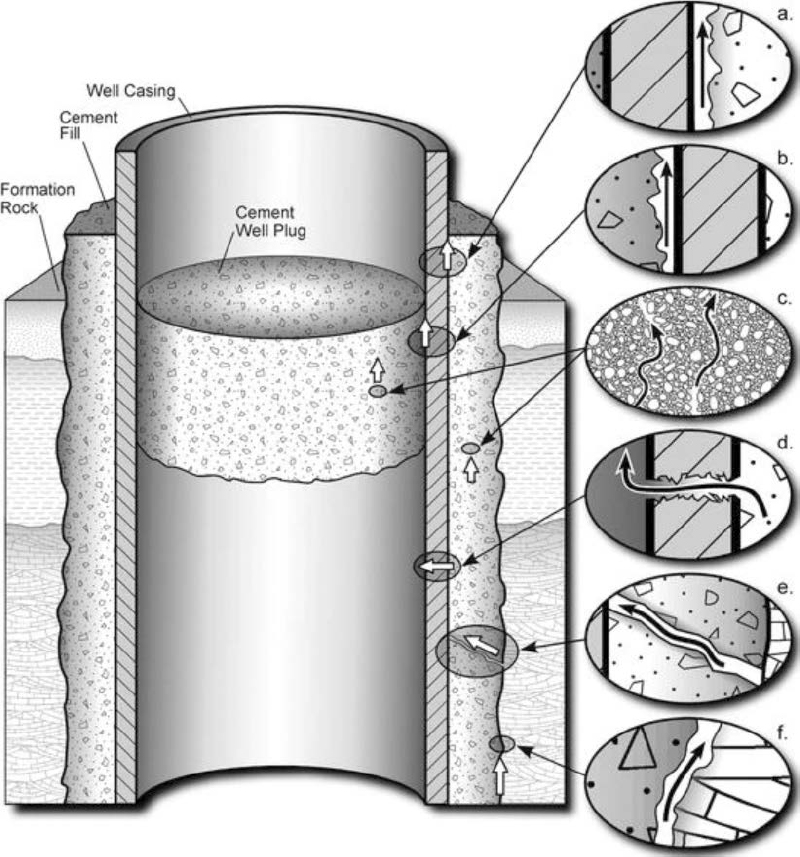
SOURCE: Gasda et al. (2004).
the wellbore at the natural seal location” (API 2021, p. 5). The base and top of plugs are set across competent rock formations, creating a continuous permanent barrier across the wellbore. Factors used to determine barrier type include wellbore condition and the type of isolation needed. Figure 3-2 depicts the isolation process of a continuous seal.
Barrier types include both mechanical and cement plugs. Mechanical plugs are typically set inside casing to isolate perforations, and cement plugs are placed across formations of competent rock. Cement plugs, such as balanced plugs, are typically set in openhole conditions, across casing shoes, or inside of casing near the surface of the wellbore. If isolating a particular interval, balanced plugs are set a certain distance below and above that interval. Local regulators set minimum criteria for length of these plugs. Cement barriers can be applied using the perforation, wash, and cement (PWC) method, which establishes a continuous barrier isolating the casing annulus and wellbore in a single operation (similar to primary cementing operations), and squeeze cementing methods, which pump cement for isolating completion intervals or open perforations. Mechanical plugs without cement are generally not recognized as suitable barriers for permanent abandonments within industry, as mechanical barrier components can degrade over time because of aspects of the well environment, such as temperature, pressure, and fluid type. Mechanical plugs are typically used as a reliable base for cement but not as the primary barrier (API 2021).
Geological Factors
When choosing a barrier type, the subsurface stratigraphy at and adjacent to the well is assessed for multiple factors. A major determining factor is understanding which zones require isolation so that liquids and gases are prevented from migrating from a geologic formation and contaminating the groundwater, surface, or atmosphere. Hydrocarbon reservoirs, coal seams, and methanogenesis in and around the wellbore are possible sources of migrating methane (Gianoutsos et al. 2024). Most states require isolation of producing intervals, hydrocarbon-bearing zones, and usable water formations. Oil and gas wells in some areas of Appalachia may require additional isolation across coal seams. In Pennsylvania, for example, requirements vary based on whether the coal seam is considered workable, whether coal has been removed, or whether a well has been drilled through a coal pillar.2 Other zones that need to be considered for isolation include potential flow zones to prevent possible cross flow of fluids within the wellbore and to the surface (API 2021).
Additional geologic factors to consider for isolation include potentially corrosive formations, such as salt or anhydrite; possible faulting; and, when known, future operational field plans such as injection activities (API 2021). Flow from corrosive formations can negatively impact casing or cement and contribute to plug degradation. Pre-existing or naturally occurring faults can serve as conduits for the migration of subsurface fluids, and fault reactivation can pose additional risks to the subsurface. Recent studies have
___________________
2 25 Pa. Code § 78.83 (Oil and Gas Wells: Surface and Coal Protective Casing and Cementing Procedures), § 78a.83 (Unconventional Wells: Surface and Coal Protective Casing and Cementing Procedures).

NOTES: The far-left diagram shows potential flow zones and the natural formation seal. The second from left shows a drilled well through the natural seal and potential flow zone; the orange area represents an open hole. The third from left shows that the well has been cased and cemented across the potential flow zone and natural seal. The far-right diagram shows that a cement plug has been placed in the casing to isolate the potential flow zone and across the natural seal.
SOURCE: API (2021).
shown that fracking can create new fracture networks that may increase the risk of methane migration toward existing abandoned wells (Brantley et al. 2014; Brownlow et al. 2016; Gianoutsos et al. 2024; Lacombe et al. 1995).
Materials, Equipment, and Processes
A second set of determining factors in choosing a barrier type and equipment includes well configuration and wellbore condition, such as primary cement and casing quality. As described earlier in this chapter, barrier types include both mechanical plugs (e.g., bridge plugs, cement retainers) and cement plugs (e.g., balanced plugs) (see Figures 3-3 and 3-4).
Mechanical plugs are typically set above open perforations and inside casing to isolate perforations. Most regulatory bodies require that cement then be placed on top of a bridge plug for additional isolation: “A well-placed zonal isolation within a caprock, with competent backside cement and a fit for purpose isolation medium placed inside casing, forms an isolation system that maximizes the probability of providing a permanent rock-to-rock wellbore seal” (Energy Safety Canada 2022, p. 13).3 Cement retainers are used to pump cement below the retainer into open perforations or add cement to improve annular cement quality. Once the cement has been pumped, the tubing is removed from the retainer, and the cement becomes a mechanical plug (Figure 3-5).
According to American Petroleum Institute’s (API’s) Recommended Practice 65-3, Portland cement is the accepted material for plugging operations (API 2021). It is important that cement standards for plugs meet the same standards as primary cementing requirements to cement well casing during the well construction phase. API Specification 10A establishes cement requirements (API 2019). Those that affect barrier performance include the following (API 2021):
- Density to achieve effective mud removal and maintain an overbalanced pressure.
- Compressive strength to meet minimum regulations but also to meet integrity of the barrier for long-term effectiveness. API indicates that a minimum strength of 3,500 kPa (500 psi) is adequate unless otherwise specified by regulations (API 2021, p. 22).
- Thickening time to be able to place the barrier within the time needed.
- Free fluid to reduce the chance of channels or voids.
Ideally, cement for plugging operations is tailored to local conditions, such as bottomhole temperatures, corrosive environments, and other wellbore conditions. Specialized additives and fluids are often required. For high-pressure/high-temperature wells, retarders prevent premature setting, and silica flour improves strength retrogression resistance. For corrosive zones, latex, resins, or pozzolanic blends4 can reduce
___________________
3 “Backside cement” is also called annular cement (see annulus in the Glossary [Appendix B]).
4 For a definition of pozzolanic blends, see the Glossary in Appendix B.
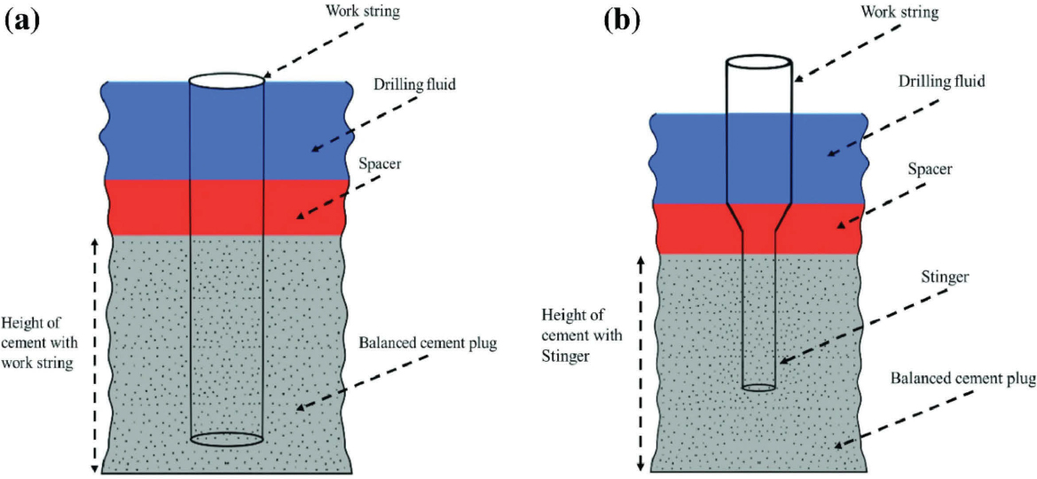
NOTE: The American Petroleum Institute’s Recommended Practice 65-3 addresses the process of setting a balanced cement plug.
SOURCE: Khalifeh and Saasen (2020). CC BY 4.0.
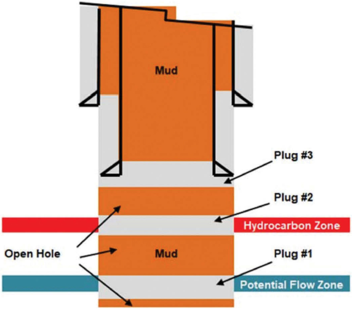
SOURCE: API (2021).
micro-annulus (small gap) formation. Lost circulation materials (e.g., granular, flake, fiber, graphite; a combination of materials) may be necessary to maintain plug placement in highly fractured formations (API 2021; Aslani et al. 2022; Broni-Bediako et al. 2016).
In addition to additives that enhance placement and strength, materials are being designed to improve the mechanical resilience and self-healing capacity of the cement sheath. Micro-encapsulated polymers, expansive agents, and crystalline growth additives can help the set cement close micro-annuli or small cracks that might otherwise evolve into leakage pathways. For example, self-healing cements incorporating super-absorbent polymers or hydrophilic crystalline additives can swell upon contact with water or hydrocarbons to re-establish zonal isolation (Energy Safety Canada 2022; IOGP 2017; King and King 2013; see also Chapter 6).
Whenever possible, uncemented casing is first removed to allow for more effective wellbore preparation and to improve barrier placement. However, if a well contains poor-quality cement or casing that cannot be pulled out but has uncemented openhole sections, section milling or the PWC method can be employed to form an acceptable
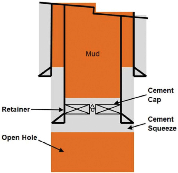
NOTE: The retainer allows cement or other fluids to be directed to specific places in the wellbore and is often used to squeeze cement into existing perforations to improve the existing primary cement seal.
SOURCE: API (2021).
barrier to isolate the required formations. Section milling is a method to create a cross-sectional barrier directly toward a “clean” formation in the event an annulus material is inadequate as a barrier (Vrålstad et al. 2019). Special blades and cutters are used to remove designated well sections in situations where the casing string is fully or partly cemented (Vrålstad et al. 2019). Because of cost and time constraints, section milling is typically used only for eliminating annular pressure due to poor cement quality. To address these constraints, industry and academia are focusing considerable effort on technology development to increase efficiency and operational safety (see Chapter 6 for examples). PWC can be used to establish annulus barriers when the annulus is uncemented or partly filled with poor cement (Vrålstad et al. 2019). This process involves perforating the casing to reach the annulus; cleaning out mud, debris, settled barite, or poor cement; and then pumping new cement into the annulus (Vrålstad et al. 2019). PWC can be very time saving and cost-effective; before placing cement in the annulus, neither section milling nor cut-and-pull of casing is required. Additionally, PWC establishes a continuous barrier isolating the casing annulus and wellbore in a single operation (API 2021).
Barrier Verification Requirements
An important step in the plugging process is verifying both external (e.g., casing or annular cement sheath) and internal (e.g., plugs) well barrier location and integrity. “Because the purpose of well plugging is to seal the wellbore, the competence, placement and verification of plugs are critical” (GWPC 2023, p. 63). The Ground Water Protection Council (GWPC 2023) also recommends that states consider the witnessing of critical well plugging operations—particularly those on barrier verification—by agency representatives. Verification begins with design review to confirm that regulatory requirements and industry practices for material specifications, placement method, and position are met. Where feasible, it is best practice to verify all barriers placed during the process. If unable to do so, best practice then calls for verifying barriers that isolate producing formations and protected water to confirm isolation. External barrier verification includes recording the volume of material used, displacement volume, surface returns, and pump pressure. To determine the effectiveness of the external barrier, a cement evaluation tool—such as a cement bond log, variable density log, or ultrasonic/radial tool—is used to confirm that all formations are effectively isolated and meet minimum standards for full isolation (API 2021).
Internal barrier verification requires tagging the surface of the plug to verify that the top of the depth is as designed and/or testing to confirm that internal pressure will meet the competency requirements (API 2021). Well condition and the plug’s location within the wellbore determine the type of internal verification needed. NORSOK (2024) lists several methods, based on wellbore configuration, for verifying that a barrier meets design requirements to prevent flow out of the isolated interval. Table 3-1 summarizes verification methods based on barrier type and well configuration.
Inspections
Documenting well plugging inspections is critical for future evaluations of leaks and determining site suitability for proposed future subsurface uses (Lackey and Dilmore 2021). Inspection details may be documented in the post-plug report or a subsequent report of abandonment for the well file. In public information-gathering sessions with the Interstate Oil & Gas Compact Commission (IOGCC) 2025 Annual Business Meeting participants on May 21st and 22nd, and state representatives and plugging and
TABLE 3-1 Summary of Verification Methods Based on Barrier Type and Well Configuration
| Method | Verification type |
|---|---|
| Openhole balanced plug | Tag plug |
| Balanced plug inside casing | Tag plug and pressure test |
| Secondary plug inside casing | Tag plug |
| Perforate, wash, and cement | Run cement evaluation tool |
abandonment contractors on July 22nd, the committee learned that requirements for inspection or witnessing of plugging operations vary by state.
In a Ground Water Protection Council report on state regulations, only 8 out of 27 states required witnessing (GWPC 2023). Witnessing may involve observing and confirming the setting of mechanical barriers, such as bridge plugs or cement retainers, and setting of cement plugs to ensure they meet required quality and depth.
States commonly require inspections before, during, and after plugging. Inspection before plugging can include an assessment of the well site and wellbore condition, which informs the plugging plan. Inspectors may identify potential hazards and ensure the site is stable enough for plugging, including testing for leaks or emissions and assessing for site access issues.
Inspections and documentation during the plugging operations cover current well conditions and any associated remedial actions as well as meetings with plugging contractors to review compliance with safety regulations5 (BLM 2019). The top plug is monitored for any indication of failure, which may include gases leaking through the cement or significant cement fallback (Simmers et al. 2024). Following plugging operations, inspections confirm that the well is properly sealed and no longer at risk of leaks or emissions. While the goal of most state oil and gas agencies is to deploy personnel to witness and/or inspect critical plugging operations—as the committee learned during the May and July 2025 information-gathering sessions noted above—several states discussed insufficient staffing levels for universal coverage.
CAUSES, PREDICTABILITY, AND ROOT CAUSE FAILURE ANALYSIS
As noted at the beginning of this chapter, the primary goals of wellbore plugging and abandonment are natural resource protection, interval isolation, and leak and cross-flow prevention. Therefore, if a plugged and abandoned well fails to meet any one of these primary goals, it can be considered a failure. However, the consequences and severity of failing to meet a goal may not be the same. For example, failure to prevent unintended cross flow may create operational risks in terms of nearby hydrocarbon production or underground injection activities but not endanger usable water sources or lead to surface leakage that impacts public health or the environment.
The root cause of well failures is difficult to determine because of limited available data. While root cause failure analyses require data collection on failures as they are identified and addressed, analyses also require data collection on the well and plug characteristics prior to a failure. Key data points, which the committee noted many states now collect, include the following:
- Historical well drilling, construction, and operations records (if available)
- Approved well plugging procedures
- Post-plugging wellbore schematic
___________________
5 California Tit. 14, § 1723.7—Inspection of Plugging and Abandonment Operations.
- Post-plugging report elements
- Information on well design and construction
- Plug type
- Number of plugs placed
- Placement method, placement verification
- Cement records (including contractor cement tickets)
- Well integrity and barrier verification test results
- Variations from approved plugging procedures, reasons for those variations, and any other complications encountered during plugging operations and post-plugging well failures
Nonetheless, several underlying factors that contribute to a plugging failure were identified by the committee. Both cement and mechanical plugs can fail for any number of reasons, including poor initial well construction and human error, poor current well integrity, low-quality material, inadequate cement slurry design for the given wellbore conditions, improper mixing of cement and cement placement techniques during plug installation, and cement deterioration due to factors such as corrosion. In addition, differences in how wells were constructed and plugged throughout the history of oil and gas development and across different geographies contribute to failures. As described in Chapter 2, regulatory practices have evolved but not necessarily in tandem across jurisdictions, and industry-wide standards were only established relatively recently.6 The rest of this section provides additional detail on subsurface factors that can contribute to plugged well failures, including faulting, corrosion, and other subsurface processes.
Subsurface Conditions
Despite best efforts to account for them, subsurface conditions can contribute to plug failures. Such conditions include both natural and induced fracturing and faulting; subsurface reservoir characteristics; and active subsurface processes, such as subsidence, corrosion, and fluid migration.
Fracturing and Faulting
Fractures and faults, whether natural or induced, can play a major role in plug failure. Fracture networks can allow subsurface fluids and pressure to escape, thus defeating efforts at zonal isolation. They can also cause wellbore deformation, which may create additional leakage pathways. Dormant faults can become reactivated, potentially providing conduits for subsurface fluids to migrate to different zones or to the surface. For example, the low density and volatility of natural gas allow it to migrate
___________________
6 Industry standards that play an important role in well construction and plugging operations include API Standards 10A, “Specifications for Oil-Well Cements and Cement Additives.” These standards were first published in 1953 and have been reviewed and revised multiple times since. Other cement standards include API RP 10B-2 on cement testing and API RP 10D-2 on centralizer placement. It was not until 2021 that API published the first edition of API RP 65-3 Well Plugging and Abandonment.
easily between zones in the subsurface and vent to the atmosphere via leaks or fissures associated with either faulting or a mechanical failure in a well (Gianoutsos et al. 2024; see issues related to geochemistry in Chapter 5). In addition, faulting facilitates the cross-formation movement of hydrocarbons; it can occur as a natural process within the subsurface. But new fracture networks or fissures can be created during hydraulic fracturing of producing zones within a wellbore, and faults can be reactivated during oil and gas production when reservoir compaction causes stress redistribution (Chan and Zoback 2002).
Chemical interactions of injected fluids with other materials can also pose a risk to wellbore integrity. Depending on the composition, fluid flow rate, and other factors, the fluids can react with the wellbore materials (e.g., cement, casing) and surrounding rock formations, leading to chemical degradation and barrier weakening (Crow et al. 2010; Fernandez et al. 2024). For example, carbon dioxide injection can corrode steel wellbore components and degrade the cement sheath (Crow et al. 2009). The committee noted that the type and concentration of dissolved salts, organic compounds, and other chemicals in the wastewater play a crucial role in determining the types of chemical reactions. The mineralogy and porosity of the subsurface formation as well as fractures and faults influence the wastewater flow paths and thus potential for chemical reactions. The pH and redox potential of the wastewater and subsurface environment also affect the direction and extent of chemical reactions.
Reservoir Characteristics
Certain subsurface reservoir characteristics can contribute to well plug failure, including complex stratigraphy and the rock properties of formations penetrated by the wellbore. First, when a plug has failed, stratigraphic complexity (primarily through differences in rock properties such as porosity and permeability) could result in the migration of subsurface fluids from an isolated formation to zones that may be unprotected, potentially impacting overlying aquifers and eventually reaching the surface, or the migration to the surface of various gases, which may include methane, volatile organic compounds, or hydrogen sulfide. Second, characteristics such as porosity and permeability can influence the extent to which subsurface fluids may migrate, because of either the nature of the formation or a breakdown of permanent isolation resulting from degradation in the plug material itself (Chukwuemeka et al. 2023).
Reservoir Compartmentalization
A third characteristic involves reservoir compartmentalization,7 which may impact how much subsurface fluids travel. Natural division of the reservoir into different fluid or pressure segments may prevent cross flow over production timescales but still
___________________
7 Reservoir compartmentalization is the division of a petroleum accumulation into distinct fluid or pressure segments due to sealed reservoir boundaries; it can impede fluid flow and impact production efficiency and economic viability in reservoir development.
allow fluid movement over geological timescales or under specific pressure conditions, thereby compromising long-term plug effectiveness (Ejeke et al. 2017). Finally, multiple subsurface processes can impact the occurrence and extent of plug failure. Fluid withdrawal from pore spaces can lead to compaction of the formation, which can lead to subsidence and exert stress on existing well plugs, making them more prone to failure.
Impact of Corrosion
Corrosion can break down cement and thus create pathways for oxidative corrosion of metal components that are in direct contact with water, weakening well casing and screens and leading to leaks, collapse, and failure (Jacques et al. 2010). Corrosion processes are complex and heterogeneous, controlled by groundwater chemistry (e.g., pH, salinity, dissolved oxygen); interactions among different metal compositions, cement, and other well materials; and the composition of the surrounding stratigraphy, bacteria, and groundwater in the host formations (Boyd and Skalny 2007; Sarin et al. 2004). Generally, corrosion rates increase under low pH and high total dissolved solids conditions, though dissolved oxygen and other constituents play a role (Boyd and Skalny 2007; T. Li et al. 2020; J. M. Roy et al. 2016; Skinner et al. 2025).
Specific conductance, a common water quality parameter, is used to assess the concentration of dissolved ions, such as salts and minerals in water with elevated total dissolved solute (TDS) concentrations. If groundwater with high TDS is used to mix cement or fresh cement is placed in an aquifer with high TDS, the mixture may need a special formulation to maximize strength and longevity. Groundwater with high concentrations of chloride can penetrate cement in a wellbore and react with iron and steel components to accelerate corrosion, making the cement more vulnerable to deterioration (L. Li et al. 2020). Dissolved calcium in groundwater may also be a factor in plug durability and bonding (Um et al. 2014). Likewise, sulfate can react with cement in the wellbore and plugs, reducing its strength and accelerating well deterioration (Aslani et al. 2022). This reaction may also weaken the bond between cement and the rock penetrated by the wellbore. Dissolved methane in groundwater near orphan wells may serve as an indicator of methane movement between wellbores and the aquifer (Skinner et al. 2025). In addition, the presence of in situ methane can create problems with cementing and seal material because it can cause pores to form in the cement. Further issues related to cementing and possible alternatives can be found in the section “Emerging Alternatives to Cement and Advanced Materials” in Chapter 6.
Downhole corrosion can also occur through contact with certain formations (e.g., salt, anhydrite) or carbon dioxide or hydrogen sulfide. Cement degrades in the presence of hydrogen sulfide, carbon dioxide in gaseous form or in solution, or fluids such as acidic produced water, leading to the development of micro-annuli in the cement sheath and creating an environment conducive for plug failure (Chukwuemeka et al. 2023). In certain regions such as the Gulf Coast, operators often encounter salt or briny fluids as they drill through uplifted strata along the periphery of salt domes (Hamlin 2006). Carbonic acid, formed when carbon dioxide comes into contact with water, tends to present a greater risk for corrosion, particularly with reservoirs that have been subjected
to enhanced oil recovery techniques, such as carbon dioxide injection (Laumb et al. 2016), or used for carbon capture and storage (Bradshaw et al. 2007; Laumb et al. 2016).
In addition to these issues, natural gas reservoirs usually contain a large amount of saline formation water, which often flows into the wellbore during gas production and is vaporized (Wang et al. 2023). Salt precipitation then occurs in the gas reservoirs near and even in the wellbore (Tang et al. 2023). The result can be corrosion of downhole wellbore equipment similar to that caused by formation fluids. Chapter 5 addresses potential remediation strategies for these types of problems.
Subsurface Fluid Movement and Potential Effects on Well Integrity
The characteristics and movement of subsurface fluids can serve as major determinants in well plug success or failure and highlight the importance of understanding subsurface fluid chemistry and stress redistributions following hydrocarbon extraction or subsequent injection activities (Crow et al. 2009). The Railroad Commission of Texas first required plugging abandoned wells in a manner that prevents the exchange of subsurface fluids between strata in 1919 (Chukwuemeka et al. 2023). Since then, significant efforts have been undertaken in Texas and elsewhere to better understand the types and characteristics of subsurface fluids encountered by a wellbore.
Naturally occurring subsurface fluids can exert pressure on well plugs, resulting in failure (Chukwuemeka et al. 2023). Abnormal overpressure zones can also form over geologic timescales due to the limited time for fluids to drain during rapid burial of clay and shale. These zones can result in high annulus pressure, which can compromise well integrity pressure containment barriers (Kiran et al. 2017). Activities related to injection or withdrawal of fluids can also affect well plug integrity and zonal isolation through, for example, temperature changes within a reservoir, the application of cyclic stresses in the reservoir, reservoir repressurization, and changing subsurface pore pressure in proximity to pre-existing faults.
Injection of fluids into the subsurface poses risks to the integrity of a well plug, wellbore, and/or casing. Recent studies have examined these risks, especially in the Permian Basin of west Texas, where wastewater injection in particular has led to unintended consequences, such as wastewater leakage, sinkhole subsidence, and fault movement (Denlinger and O’Connell 2020; Karanam et al. 2024). Injected fluids can change the pore pressure within and around the adjacent rocks and pre-existing faults, which can reduce the frictional resistance on the faults and make them more likely to slip, resulting in seismic activity (Currie et al. 2018; NRC 2013). These earthquakes can further compromise wellbore and well plug integrity by generating additional fractures, creating new pathways for fluid migration (Karanam et al. 2024), altering the stress state of the surrounding rocks and faults, or increasing subsurface pressure beyond that which a well plug can withstand (Currie et al. 2018; Denlinger and O’Connell 2020; Hennings et al. 2024; Karanam et al. 2024; Kiran et al. 2017; Smye et al. 2024). Even if change in pore pressure might not reach the fault directly, it can alter the overall stress field in the region, making faults more prone to rupture in response to distant seismic events or even changes in regional stress patterns (Hennings et al. 2024).
Temperature changes in the reservoir can occur from heating and cooling fluids, which can cause them to expand or contract (Craft and Hawkins 1991). For example, rapid cooling (e.g., during cold fluid or liquid carbon dioxide injection) compromises well integrity by causing the casing and cement to contract, which can lead to a micro-annulus at the cement-casing or formation interface and can provide a pathway for fluid or gas migration (Nygaard et al. 2014). On the other hand, excessive heating can lead to high compressive stresses and can cause the cement to crack or lose strength over time (P. Roy et al. 2016). For unconventional resources, cyclic stresses may be induced because of frequent changes between hydrocarbon production and injection, which can accelerate barrier degradation (Ahmed and Salehi 2021). Subsurface activities such as waterflooding (a secondary recovery process in which produced water is reinjected into the producing reservoir to increase oil production), gas injection for storage—including carbon dioxide storage—and leaks from other reservoirs can repressurize reservoirs. Without a surface expression, subsurface leaks or fluid migration in these cases could go undetected.
PREDICTING PLUGGED WELL FAILURES
The previous sections described several factors that could contribute to plugged well failures. However, as noted, very few data are available to provide a root cause analysis for each failure. During the committee’s open information-gathering session on May 21st and 22nd with IOGCC 2025 Annual Business Meeting participants, state representatives said that the few plugged well failures they have seen were discovered only when a landowner complained. Because of the lack of data, cause of failure is only circumstantial. In the May 2025 session, a state representative from Michigan highlighted a situation in which a well plugged with heavy mud failed when a new waterflood project went into operation. This could have been due to well plugging that took place prior to industry standards and regulation. In an information-gathering session on July 22nd, 2025, with state representatives and plugging and abandonment contractors, a state representative from Texas discussed a failure in which a residential developer reported a potential leak—evidenced by “bubbling” coming up from the ground following a rainstorm at the development site—and remediation processes revealed that no plugs, or even casings, were recovered. This could have been because the materials disintegrated over time.
Predicting plugged well failures requires more data than are publicly available or accessible. More data about wells’ histories, wellbore schematics, post-plug activities, and other elements described earlier in this chapter would allow governmental agencies, operators, and contractors plugging orphan wells to discuss and understand the causes of failure and begin to determine causal mechanisms and whether failures can be predicted.
As part of the effort to plug orphan wells using the U.S. Department of the Interior Orphaned Wells Program Office funds, federal guidelines originally required grantees to conduct methane measurements both pre- and post-plugging, which would have provided additional data on orphan well methane emissions (OWPO 2023). Another potential source of data could be integrity failure in active wells, as this can be a
precursor to failure in plugged wells. Additionally, the age of a well that is being plugged is significant not only because it can indicate the potential for age-related degradation of its components but also because of the historical changes in composition of materials in the well and the impact of industry technology and regulatory changes on well integrity over time (King and King 2013).
If more data were available, predictive analysis tools could be used to assess a plugged well’s integrity to determine leakage probability and quantify risk using failure mode, effect, and critical analysis. Better characterization of risk could then be used to evaluate barrier elements most likely to fail and the failure mechanisms. Recent modeling efforts have shown both the promise of these predictive tools as well as the work still needed to be able to use them effectively (e.g., Montague et al. 2018; Zheng et al. 2024).
CONCLUSIONS AND RECOMMENDATIONS
Conclusion 3-1: Verification of permanent barriers is a critical component of plugging operations to confirm barrier competence and full isolation, to help prevent environmental contamination, and to ensure public health and safety. Verification includes the critical steps of design review, inspection and testing, and documenting and witnessing.
Recommendation 3-1: Regulatory agencies involved in plugging and abandonment should require a barrier verification plan with defined acceptance criteria in the approved plugging plan. Agencies should specify when permanent barriers must be verified and the minimum methods to be used for inspection and testing (e.g., tagging, pressure testing, and logging). An agency representative should be on site to witness critical operations and confirm compliance, and verification results should be documented in post-plugging reports.
Recommendation 3-2: Plugging orphan wells is effective for reducing leaks and emissions, and states should continue to focus on plugging orphan wells following best practices and accepted industry standards. Future federal and state funding should be considered to provide states added support for their work.
Conclusion 3-2: Access to orphan well data is important to many stakeholders, including the public, the oil and gas industry, future users of the subsurface, and researchers. The most important data to collect are well drilling, construction, and operations records; approved well plugging procedures; and post-plugging reports.
Conclusion 3-3: Records of any observed variations from approved plugging procedures are valuable yet are not generally captured in existing forms. Collecting this information as a standard practice would enable pluggers to more accurately assess well integrity, help regulatory agencies continuously improve practices, and provide information needed if surrounding wells are repurposed.
Conclusion 3-4: There were not enough publicly available data (e.g., on well integrity, instances of failure, and actions to resolve failures) for the committee to complete a probabilistic assessment of well failures or to understand the likelihood of failures. Gathering information on well plug failures would be valuable to gain insight into their causes, frequency, and associated emission rates.
Recommendation 3-3: A reporting and corrective action system should be implemented to improve essential data collection and analysis of plugged well failures. Such a system could also provide common organization and storage for well drilling, construction, and operations records; approved well plugging procedures; and post-plugging reports.


