Delineation of Linear Roadside Hardware Systems and Roadside Obstacles (2026)
Chapter: 8 Concrete Barrier Delineation

CHAPTER 8
Concrete Barrier Delineation
Different practices for delineating concrete barrier systems are presented in this chapter. These practices can be considered for temporary and permanent concrete barrier types.
Delineators
Description
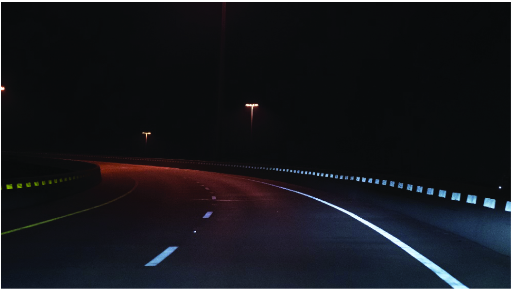
Concrete barrier delineators consist of a base material with retroreflective sheeting. The base material is commonly plastic but can be made of other materials, such as metal. Delineators are attached to the side or top of the concrete barrier where the retroreflective sheeting extends from the face of the concrete barrier and faces vehicular traffic. Figure 57 shows an example of delineators attached to the side and top of a concrete barrier system.
Effectiveness
A CMF has not been established for delineators attached to concrete barrier systems. No crash data analysis studies have been performed to evaluate the effectiveness of delineators in reducing the number or severity of crashes. A human factors study conducted under NCHRP Project 22-53 (see Part I of this report) demonstrated that concrete barrier delineators significantly enhanced driversʼ ability to detect upcoming curves compared to the absence of delineation. This effect was observed for delineators mounted either on the side or the top of the concrete barrier. These findings were based on an evaluation of a concrete barrier installed on a curved roadway in dry nighttime conditions.
Application
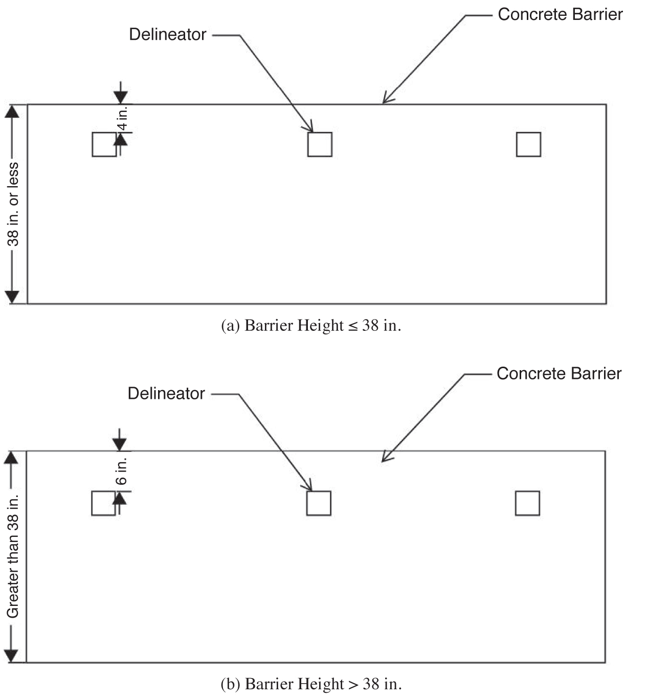
Delineators are attached to a concrete barrier system using adhesives or mechanical fasteners. It is good practice to mount side-mounted delineators near the top of the concrete barrier to improve visibility and reduce the likelihood of dirt accumulation from the roadway. Figure 58 shows recommended mounting heights for side-mounted delineators based on the height of the concrete barrier system.
Top-mounted delineators may present a functional advantage when concrete barriers are subject to snowplowing effects. They are less prone to the accumulation of snow and debris and less likely to be dislodged compared to side-mounted delineators.
In current practice, delineator spacing on concrete barrier systems varies by roadway geometry. Most states use 25- to 50-ft spacing on curved sections and 100- to 200-ft spacing on tangents. According to the findings presented in Chapters 3 and 4 of Part I of this report, drivers preferred

Long Description.
Illustration A depicts the barrier height less than or equal to 38 inches. The illustration shows a rectangle-shaped structure with the length marked 38 inches or less. The width is marked as the concrete barrier. Three small squares are located close to the concrete barrier labeled as delineators. The distance between the concrete barrier and the delineator is marked as 4 inches. Illustration B depicts the barrier height higher than 38 inches. Illustration B is similar to A, but the length of the rectangle is marked as greater than 38 inches. The distance between the delineator and the concrete barrier is marked as 6 inches.
closer delineator spacing on curves because it improved their ability to identify the curve earlier in the driving route. Side-mounted and top-mounted delineators are recommended to be spaced at the following distances when installed on concrete barriers:
- Curve Radius ≤ 500 ft: 25-ft spacing
- Curve Radius ≤ 1,000 ft: 50-ft spacing
- Curve Radius > 1,000 ft and Straight Roadways: 100-ft spacing
Following MUTCD guidance, the color of the retroreflective sheeting should match the color of the edge line (FHWA 2023). For median concrete barrier installations with top-mounted delineators, bidirectional retroreflective delineators should be used to delineate both vehicle travel directions. Concrete barriers installed on the outside curve of an undivided two-way, one-lane roadway can also benefit from bidirectional retroreflective delineators, which provide delineation for both directions of vehicle traffic. Retroreflective sheeting should also conform to MUTCD guidelines by having “a minimum vertical and horizontal dimension of 3 inches.” The sheeting should also be capable of “clearly retroreflecting light under normal atmospheric conditions from a distance of 1,000 feet when illuminated by high beams of standard automobile lights” (FHWA 2023).
Delineator Panels
Description
Delineator panels consist of a long strip of base material, typically aluminum, with retroreflective sheeting across the entire strip. Delineator panels attach to the side of the concrete barrier system. Some devices contain waves along the length of the panel to improve retroreflectivity angles. The panels are spaced close together to create the effect of a continuous line of delineation along the concrete barrier system. Figure 59 shows an example of a series of delineator panels attached to a concrete barrier.
Effectiveness
A CMF has not been established for delineator panels attached to concrete barrier systems. Oregon DOT evaluated the use of delineator panels on concrete barriers in work zones (Haas 2004). During a 12-month observance period, the research team reported that the vehicle speeds reduced when delineator panels were installed on concrete barriers in work zones. However,
some of the speed reduction was attributed to traffic congestion. A simple before-and-after crash data analysis was performed to evaluate the effect of delineator panels on concrete barrier systems (see Part I of this report). The study identified a positive safety effect associated with installing delineator panels on concrete barrier systems, evidenced by reductions in injury-related, non-injury-related, nighttime, and overall crashes.
Application
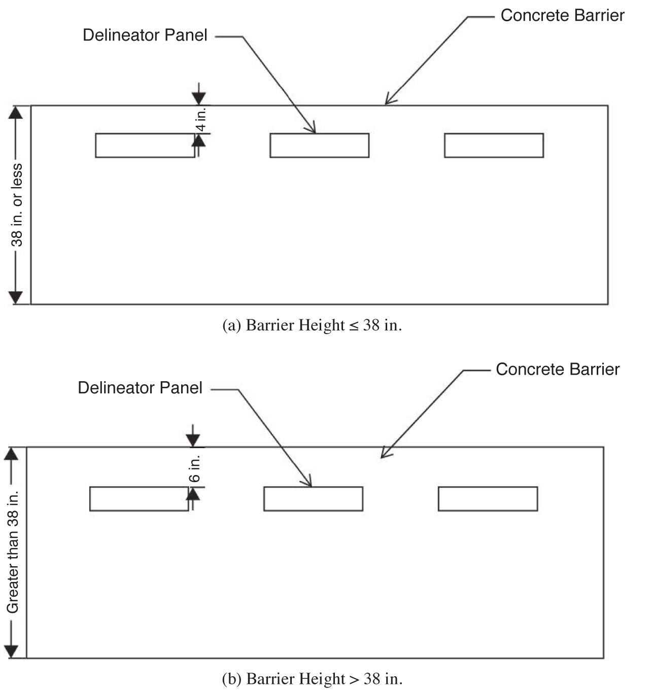
Delineator panels are attached to a concrete barrier system with adhesives or mechanical fasteners. It is good practice to mount the delineator panels near the top of the concrete barrier to improve visibility and reduce the likelihood of dirt accumulation from the roadway. Additionally, placing the delineator panels higher on the concrete barrier helps minimize the effects of snowplow operations by reducing dirt accumulation and the risk of dislodging the delineator panel. Figure 60 shows recommended mounting heights for delineator panels based on the height of the concrete barrier system.
As mentioned previously, delineator panels are typically spaced closer together to create an effect of continuous delineation along the concrete barrier system. Thus, delineator panels are recommended to be spaced at the following distances when installed on concrete barriers:
- Curve Radius ≤ 500 ft: 10-ft spacing
- Curve Radius ≤ 1,000 ft: 20-ft spacing
- Curve Radius > 1,000 ft and Straight Roadways: 100-ft spacing
Long Description.
Illustration A depicts the barrier height less than or equal to 38 inches. The illustration shows a rectangle-shaped structure with the length marked 38 inches or less. The width is marked as the concrete barrier. Three small rectangles are located close to the concrete barrier labeled as delineator panels. The distance between the concrete barrier and the delineator is marked as 4 inches. Illustration B depicts the barrier height higher than 38 inches. Illustration B is similar to A, but the length of the rectangle is marked as greater than 38 inches. The distance between the delineator panel and the concrete barrier is marked as 6 inches.
Following MUTCD guidance, the color of the retroreflective sheeting should match the color of the edge line (FHWA 2023). Retroreflective sheeting should also conform to MUTCD guidelines and be capable of “clearly retroreflecting light under normal atmospheric conditions from a distance of 1,000 feet when illuminated by high beams of standard automobile lights” (FHWA 2023).
Chevrons
Description
Chevrons mounted to sign support structures are often used to delineate roadway horizontal curves. Some roadway applications may not have sufficient space for placing and installing a support system with the chevron. For example, in situations involving a median concrete barrier on a curved roadway, the sign support and chevron must be mounted to the top of the concrete barrier. While it is an acceptable practice, other alternatives may be desired to avoid attaching a support structure to the top of the concrete barrier. One such alternative is to mount chevrons directly to the side of the concrete barrier. Figure 61 shows an example of a series of chevrons painted white attached to a concrete barrier.
Effectiveness
A CMF has not been established for chevrons attached to concrete barrier systems. No crash data analysis studies have been performed to evaluate the effectiveness of chevrons mounted on concrete barriers in reducing the number or severity of crashes. A human factors study conducted under NCHRP Project 22-53 (see Part I of this report) demonstrated that chevrons mounted on concrete barriers did not significantly improve driversʼ reaction in nighttime conditions compared to concrete barriers with no delineation. A component of the lack of nighttime effectiveness was attributed to poor retroreflectivity angles of the chevrons on the concrete barrier. The study did identify, however, a slight increase in curve detection in daytime conditions. The chevrons were evaluated on a concrete barrier system placed along a curved roadway with a 600-ft radius.
Application
Chevrons are attached to a concrete barrier system with adhesives or mechanical fasteners. To increase the visibility of the chevrons, they should be attached near the top of the concrete

barrier. Thus, a mounting distance of 2 in. from the top of the concrete barrier to the top edge of the chevron is recommended. Section 3G of the MUTCD provides guidance for placing chevrons along horizontal roadway curves (FHWA 2023). Because of decreased retroreflectivity angles, closer spacing is recommended when mounting chevrons on concrete barrier systems. Chevrons are recommended to be spaced at the following distances when installed on concrete barriers:
- Curve Radius ≤ 200 ft: 20-ft spacing
- Curve Radius ≤ 400 ft: 40-ft spacing
Chevrons mounted on concrete barriers on a curved roadway with radii over 400 ft are not recommended because the drivers will have limited sight of the chevrons. This limitation in visibility is due to the inability to rotate chevrons, which are constrained by the barrierʼs angle in relation to the tangent approach. The chevron design should follow standard MUTCD guidance, specifically Section 2C.08, for chevron alignment signs (FHWA 2023).
Continuous Retroreflective Paint Stripe
Description
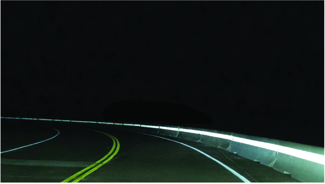
A continuous line of retroreflective paint can be applied along the length of the concrete barrier system. This practice involves applying a thin paint stripe to the concrete barrier system and retroreflective beads to the surface of the paint. Figure 62 shows an example of a concrete barrier system with a continuous retroreflective paint stripe.
Effectiveness
A CMF has not been established for the use of a continuous retroreflective paint stripe on concrete barrier systems. No crash data analysis studies have been performed to evaluate the effectiveness of a continuous retroreflective paint stripe on concrete barrier systems in reducing the number or severity of crashes. A human factors study conducted under NCHRP Project 22-53 (see Part I of this report) demonstrated that applying continuous retroreflective paint stripes along the lengths of concrete barriers effectively improved driversʼ detections of upcoming curves compared to the absence of delineation. This improved recognition resulted in drivers releasing the throttle and applying the brakes earlier in the driving route before entering the curve. Furthermore, drivers reduced their speed while navigating the curve because of the continuous retroreflective paint stripe compared to the absence of delineation. These findings
were based on an evaluation of concrete barrier systems installed on a curved roadway in dry nighttime conditions.
Application
A continuous retroreflective paint stripe should be applied to the side of the concrete barrier system. It is good practice to apply the paint stripe near the top of the concrete barrier to improve visibility and reduce the likelihood of dirt accumulation from the roadway. Figure 63 shows recommended application heights for the continuous retroreflective paint stripe based on the height of the concrete barrier system.
Following MUTCD guidance, the paint color should match the color of the edge line (FHWA 2023). The recommended retroreflective glass beads to be used for this application are Type III high-index reflective glass beads.
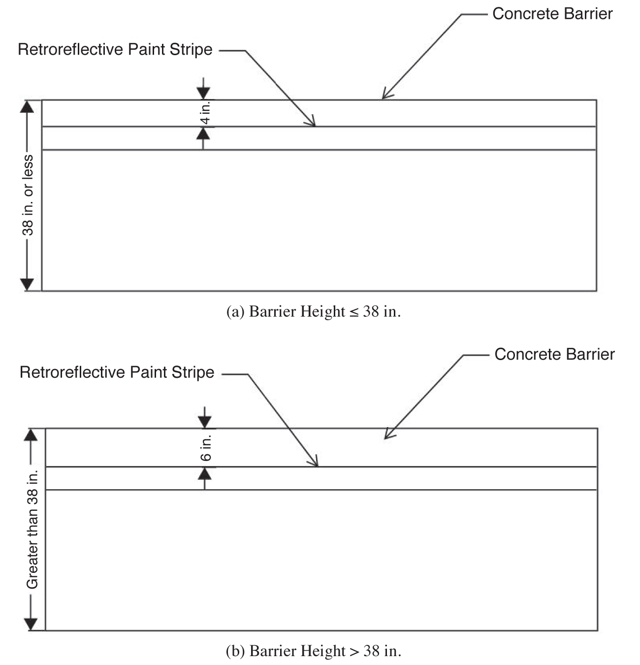
Long Description.
Illustration A depicts the barrier height less than or equal to 38 inches. The illustration shows a rectangle-shaped structure with the length marked 38 inches or less. The width is marked as the concrete barrier. There are two parallel horizontal lines close to the concrete barrier, and the line closest is labeled as a retroreflective paint stripe. The distance between the concrete barrier and the retroreflective paint stripe is marked as 4 inches. Illustration B depicts the barrier height higher than 38 inches. Illustration B is similar to A, but the length of the rectangle is marked as greater than 38 inches. The distance between the retroreflective paint stripe and the concrete barrier is marked as 6 inches.


