Delineation of Linear Roadside Hardware Systems and Roadside Obstacles (2026)
Chapter: 2 Background and Current Practice

CHAPTER 2
Background and Current Practice
This chapter contains information related to the delineation of roadside hardware and obstacles. The information was obtained through a literature review and a survey of state DOT agencies. This chapter is divided into two sections: (1) a review of previous research on the delineation of roadside hardware and obstacles and (2) a review of the current state of practice for delineating roadside hardware and obstacles.
Previous Research
A Texas A&M Transportation Institute (TTI) research study investigated the delineation of bridges and culverts on Texas roadways (Ullman and Pezoldt 1996). A controlled driver study was used to examine the adequacy of current Texas DOT delineation practices. The different delineation practices for bridge ends were installed on a closed course where driver participants reacted to the practices. The delineation practices consisted of the following:
- A single delineator post
- A single object marker
- A single object marker combined with three delineator posts (spaced 25 ft in advance of the bridge end)
Different performance metrics were evaluated, such as lateral vehicle position, vehicle speed, lateral and longitudinal vehicle accelerations, and distance, to complete the maneuver. Generally, the study found that the different delineation practices were equally effective in providing the necessary information for drivers to traverse safely through the test conditions. Minor adjustments were recommended to facilitate greater understanding and implementation across the state. One of these adjustments consisted of merging several standard documents into a single one-sheet standard document that could be applied to various field conditions with bridge ends.
Ullman et al. (1988) analyzed gore area crash attenuator delineation practices in Houston, TX. Eight crash attenuator sites with different delineation applications were evaluated for the delineation of the crash attenuators through a before-and-after crash data analysis. The findings showed an approximate 50% reduction in annual repairs for sites with a delineated crash attenuator end. Lerner and Turner (1986) also investigated the delineation of crash attenuators with chevron nose panels. The results of the investigation revealed the following benefits of installing this delineation practice: increased detection time, apparent distance, and the probability of seeing.
Ullman et al. (1988) conducted another a research study that investigated the delineation of concrete barriers. Five different delineation practices were examined on IH-45 in Houston, TX, to delineate concrete barriers. These practices consisted of side- and top-mounted delineators,
with two different types of retroreflective sheeting. The study site was both a narrow freeway location and a straight roadway section. Driver participants were instructed to travel in the lane closest to the concrete median barrier with the delineation practices. The study was conducted at night in dry weather conditions.
No notable difference in driversʼ reaction to these different delineation practices was found when evaluated based on lane positioning (i.e., the distance from the edge line and occurrence of lane straddling). However, subjective driver comments indicated that delineators mounted on the side of the barrier were preferred over those mounted on the top of the barrier. Ugwoaba (1987) evaluated the effect of different delineation practices on concrete barriers. These practices included delineation types and mounting locations (i.e., side and top mounted). Ugwoaba (1987) recommended placing delineators on the side of the barrier since opposing vehicle traffic headlights can wash out top-mounted barrier delineators when they are used on concrete median barriers.
A few studies were conducted that evaluated specific devices for delineating concrete barriers. Oregon DOT evaluated a delineator panel system to be used on concrete barriers in work zones (Haas 2004). The delineator panel system consisted of 34-in-long strips of aluminum substrate with retroreflective sheeting placed along the length of the concrete barrier. During a 12-month observance period, the research team reported that the vehicle speeds reduced when the delineator panel system was installed. Consideration of further adoption and implementation of the delineator panel system was recommended for other temporary work zone sites and permanent sites with high crash histories. In addition, two barrier lighting devices were developed that could be deployed on concrete barriers (Patangia 2007). A survey conducted by Patangia showed that drivers preferred the two barrier lighting devices to standard concrete barrier delineation devices. Patangia did not discuss the specific implementation of the lighting devices in future locations or roadways.
Amekudzi et al. (2004) investigated different types of delineators for delineating guardrails based on their conspicuity, durability, maintainability, and costs. No significant difference was found among the various types of delineators evaluated. The scope of the research study did not involve assessing the effectiveness of the delineation types. To improve motorcycle impact crashworthiness, three U.S. state DOTs have installed yellow rails on the bottom of a guardrail system (Silvestri et al. 2021). Since installing these systems, the number of crashes has decreased. Despite the small sample size of state DOTs, the bright yellow continuous guardrail element may provide an additional safety benefit. Dixon et al. (2023) evaluated and developed crash modification factors (CMFs) for separated bicycle lanes. They also evaluated the safety effects of different separated bicycle lanes in three cities. The delineation practices consisted of buffers, flexible delineator posts, and various combinations of the practices. The data were analyzed for crashes involving bicyclists. A CMF of 0.47 was estimated for bicycle lanes with flexible delineator posts.
As part of NCHRP Report 500: Guidance for Implementation of the AASHTO Strategic Highway Safety Plan, Volume 7: A Guide for Reducing Collisions on Horizontal Curves, strategies for delineating horizontal curves were discussed among a panoply of potential countermeasures for reducing the number and severity of crashes on horizontal curves (Torbic et al. 2004). Installing post-mounted delineators and chevrons was presented as a strategy to reduce crash rates on sharp curves. Torbic et al. reviewed several studies conducted between 1978 and 2000. The primary benefit of the post-mounted delineators and chevrons was the improved recognition of a horizontal curve, especially those with short radii. However, the authors did not provide any formal CMFs since the results of the study provided conflicting information (i.e., some were positive, while others were more neutral). Delineating roadside objects was also discussed as an experimental strategy, but no findings or recommendations were presented for it.
Dissanayake and Galgamuwa (2017) conducted a study to estimate CMFs for lane departure countermeasures in Kansas. Several methods were used, such as the cross-sectional, case–control, and before–empirical Bayes (EB) methods. The results indicated that chevrons and post-mounted delineators effectively reduced total lane departure crashes and those crashes resulting in fatalities or injuries. The authors estimated CMFs equal to 0.85 (for all lane departure [KABCO] crashes) and 0.90 (for injury-related [KABC] crashes) for post-mounted delineators. Installing chevron signs on curves reduced KABCO crashes by 11% (CMF = 0.89) and KABC crashes by 12% (CMF = 0.88) on horizontal curves.
A study funded by Michigan DOT evaluated the then-current road delineation practices in Michigan (Ceifetz et al. 2017). A wide range of delineation practices was collected through a literature review and agency surveys and evaluated through a statistical analysis. The latter involved a cross-sectional study using the negative regression model to estimate CMFs. Although data were collected for delineator posts, no CMF could be produced for this countermeasure. Nonetheless, the cost–benefit analysis reported in the study led to the recommended wider adaptation of polyurea pavement markings, snow-plowable-raised pavement markers, and freeway lighting at interchanges.
Elvik et al. (2009) wrote a book documenting a detailed list of countermeasures for improving safety. The list covered various topics, including road users, geometric design, and enforcement. The authors extracted information from published manuscripts and governmental reports and estimated a CMF for the combined installation of edge lines, centerlines, and delineator posts for the term delineation. The CMF showed a reduction of 45% (CMF = 0.55) in KABC crashes. The CMF for the sole installation of delineator posts equaled 1.04, or an increase of 4%, for KABC crashes and 1.05, or an increase of 5%, for property damage-only (PDO) crashes. These CMFs apply to rural highways.
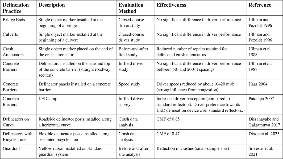
Choi et al. (2015) developed safety performance functions and CMFs for freeways located in South Korea. They examined the following independent variables: horizontal curves, vertical grades, traffic volume, segment length, lighting, median barriers, rumble strips, chevrons, and surface-mounted delineator posts. The researchers estimated a total of eight CMFs, which were estimated using the EB method. The CMF related to installing surface-mounted delineator posts equaled 1.19, or an increase of 19%, for all crash types and severities; the researchers did not explain why an increase in crashes was observed. Also, this application of delineators occurred on freeways, with the posts installed on the roadway to separate lanes. The researchers did not evaluate delineator posts installed on the roadside as part of this study. Table 1 summarizes the delineation practices identified through a review of the previously discussed literature studies. Descriptions of the delineation practice, accompanied by the evaluation method and results, are also presented in Table 1.
State of Practice
To understand the current state of practice for delineating roadside hardware and obstacles, a survey questionnaire was distributed to members of the AASHTO Committee on Design. The aim of the survey questionnaire was to collect information on the different types of delineation practices used by state DOTs, associated costs, frequency of usage, and any observed or documented safety benefits associated with each delineation practice. Appendix A comprises the questions presented in the survey, to which 33 state DOTs responded.
One of the key objectives of the survey was to collect information on current delineation practices used by state DOTs. These data were extracted from the survey and categorized
Long Description.
The table displays five columns and nine rows. The column headers are as follows: Delineation Practice, Description, Evaluation Method, Effectiveness, and Reference. The data provided row-wise are as follows:
Bridge Ends; Single object marker installed at the beginning of a bridge; Closed-course driver study; No significant difference in driver performance; Ullman and Pezoldt 1996
Culverts; Single object marker installed at the beginning of a culvert; Closed-course driver study; No significant difference in driver performance; Ullman and Pezoldt 1996
Crash Attenuators; Single object marker placed on the end of the crash attenuator; Before-and-after field study; Reduced number of repairs required for delineated crash attenuators; Ullman et al. 1988
Concrete Barriers; Delineators installed on the side and top of the concrete barrier (straight roadway section); In-field driver study; No significant difference in driver performance between 50- and 200-feet spacings; Ullman et al. 1988
Concrete Barriers; Delineator panels installed on a concrete barrier; Speed study; Driver speeds reduced by about 10–20 miles per hour (strong influence from congestion); Haas 2004
Concrete Barriers; LED lamp; In-field driver survey; Increased driver perception (compared to standard reflectors). Driver preference towards LED delineation device over standard reflectors; Patangia 2007
Delineators on Curve; Roadside delineator posts installed along a horizontal curve; Crash data analysis; CMF of 0.85; Dissanayake and Galgamuwa 2017
Delineators with Bicycle Lane; Flexible delineator posts installed along separated bicycle lane; Crash data analysis CMF of 0.47; Dixon et al. 2023
Guardrail; Yellow rubrail installed on standard guardrail system; Before-and-after site analysis; Reduction in crashes (small sample size); Silvestri et al. 2021
by hardware and obstacle type (see Appendix B). Some state DOTs provided information on delineation practices relating to interchanges, ramps, lane changes, horizontal curves, raised medians, curbs, and crossovers. This information was not included in the summary of delineation practices because it relates to the delineation of roadway alignment changes and other features that were considered outside the scope of this research effort.
In addition to providing information on current delineation practices, state DOTs were requested to provide any information on the experimental usage of other practices that may not have been implemented statewide. Six state DOTs indicated experimental usage with various delineation practices. Connecticut DOT experimented with red delineators on guardrails located on off-ramps to inhibit wrong-way driving. Colorado DOT explored placing LEDs in concrete barriers.
The California and Texas DOTs installed delineator panels on concrete barriers for enhanced delineation. Michigan DOT explored the enhanced delineation of guardrails and concrete barriers through the decreased spacing of delineators and continuous ribbon effects. Pennsylvania DOT applied continuous retroreflective paint stripe on temporary concrete barriers. These state DOTs did not report any specific conclusions about the effectiveness of these experimental delineation practices.
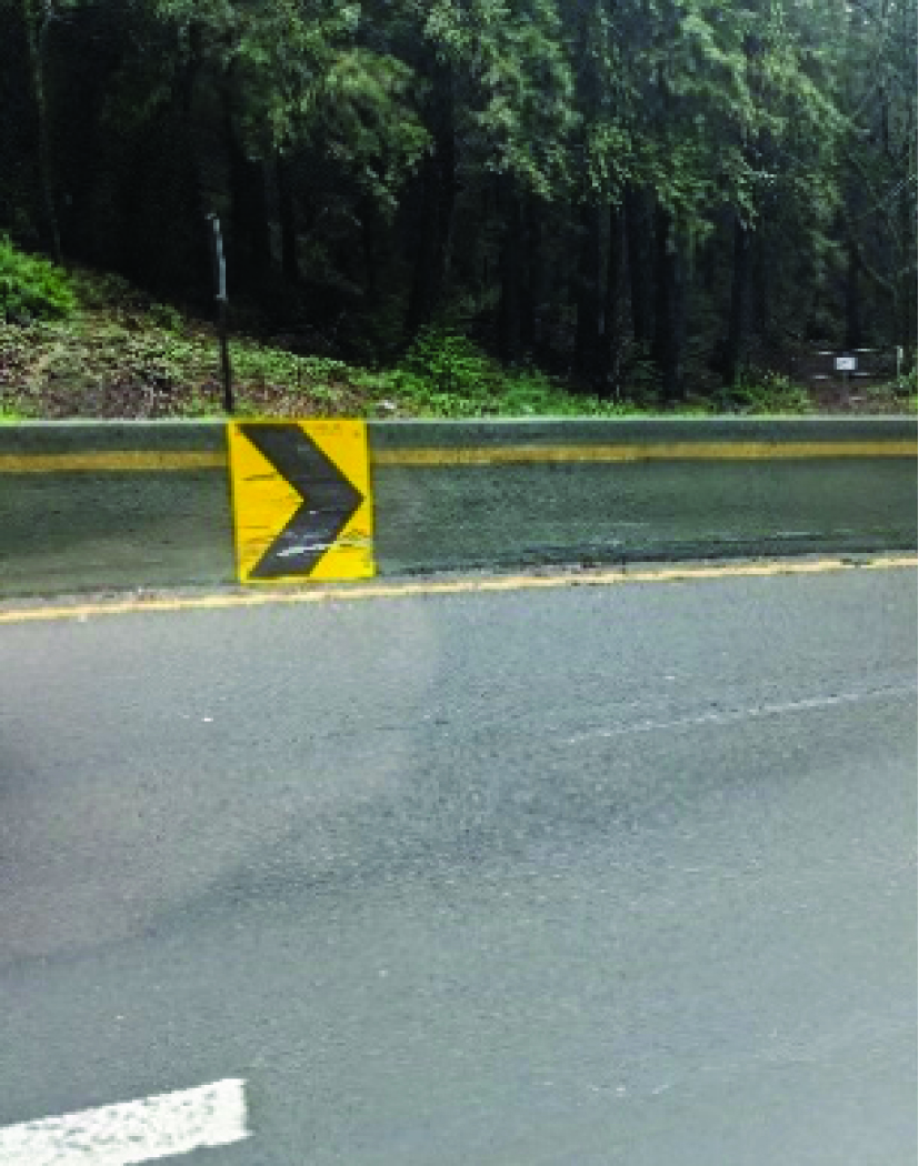
Although not mentioned in the survey by any of the state DOTs, another delineation practice was identified during the review of the current state of practice. This delineation practice consists of mounting or painting chevrons on concrete barriers to delineate curved roadway sections. This delineation practice has been experimentally used in situations such as a median concrete barrier with extreme roadway curves, as shown in Figure 1. Other applications have been considered, such as painting chevrons on a turnaround over a highway.
Synthesis
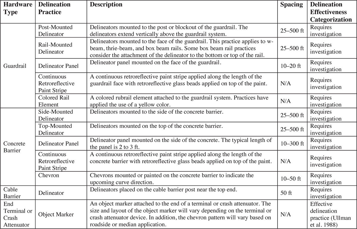
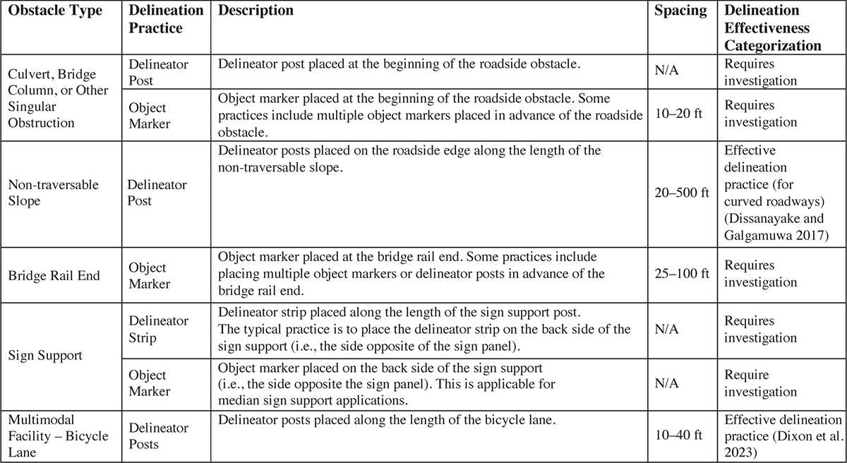
The collection of delineation practices from the literature review and state DOT survey was synthesized to identify standard delineation practices. Tables 2 and 3 summarize roadside hardware and roadside object delineation practices, respectively. The tables provide general descriptions; spacing details, if applicable; and an effectiveness categorization. Each delineation practice was categorized as effective, ineffective, or requiring investigation. An effective (or ineffective) delineation practice was identified based on previous research that determined whether the delineation practice was effective (or ineffective) at reducing vehicle roadway departures, reducing crash severity, and increasing driver alertness and comfort. A delineation practice was categorized as requiring investigation if no previous research was conducted to evaluate the delineation practice or if the research study was limited in scope and analysis.
Based on previous research efforts, only three delineation practices were identified as effective: (1) adding an object marker to an end terminal or crash attenuator, (2) adding delineator posts on curved roadway segments, and (3) adding delineator posts along a bicycle lane. These three practices were identified as effective because a CMF below 1.0 was estimated for these delineation practices, or a reduction in crashes was documented for them. Specifically, the delineation practice of adding an object marker to an end terminal or crash attenuator did not have a calculated CMF; only a reduction in crashes was observed. Conversely, the other two delineation practices had calculated CMFs below 1.0. The remaining delineation practices have not been evaluated for effectiveness or were limited in the analysis to determine their effectiveness in reducing vehicle roadway departures, reducing crash severity, and increasing driver alertness. Many delineation practices requiring additional investigation were evaluated as part of this research effort through a crash data analysis and a human factors study.
Long Description.
The table displays five columns and four rows. The column headers are as follows: Hardware Type, Delineation Practice, Description, Spacing, and Delineation Effectiveness Categorization. The first two rows are divided into five sub-rows from the second column onwards. The data provided row-wise are as follows:
The first row is Guardrail.
The first sub-row of the first row shows Post-Mounted Delineator; Delineators mounted to the post or blockout of the guardrail. The delineators extend vertically above the guardrail system; 25 to 500 feet; Requires investigation.
The second sub-row of the first row shows Rail-Mounted Delineator; Delineators mounted to the face of the guardrail. This practice applies to w-beam, thrie-beam, and box beam rails. Some box beam rail practices consider the attachment of the delineator to the bottom or top of the rail; 25 to 500 feet; Requires investigation.
The third sub-row of the first row shows Delineator Panel; Delineator panel mounted on the face of the guardrail; 10 to 20 feet; Requires investigation.
The fourth sub-row of the first row shows Continuous Retroreflective Paint Stripe; A continuous retroreflective paint stripe applied along the length of the guardrail face with retroreflective glass beads applied on top of the paint; Not applicable; Requires investigation.
The fifth sub-row of the first row shows Colored Rail Element; A colored rubrail element attached to the guardrail system; Practices have applied the use of a yellow color; Not applicable; Requires investigation.
The second row is Concrete Barrier.
The first sub-row of the second row shows Side-Mounted Delineator; Delineators mounted to the side of the concrete barrier; 25 to 500 feet; Requires investigation.
The second sub-row of the second row shows Top-Mounted Delineator; Delineators mounted on the top of the concrete barrier; 25 to 500 feet; Requires investigation.
The third sub-row of the second row shows Delineator Panel; Delineator panel mounted on the side of the concrete. The typical length of the panel is 2 to 3 feet; 10 to 300 feet; Requires investigation.
The fourth sub-row of the second row shows Continuous Retroreflective Paint Stripe; A continuous retroreflective paint stripe applied along the length of the concrete barrier with retroreflective glass beads applied on top of the paint; Not applicable; Requires investigation.
The fifth sub-row of the second row shows Chevron; Chevrons mounted or painted on the concrete barrier to indicate the upcoming curve direction; 10 to 50 feet; Requires investigation.
The third row shows Cable Barrier; Delineator; Delineators placed on the cable barrier post near the top end; 50 feet; Requires investigation.
The fourth row shows End Terminal or Crash Attenuator; Object Marker; An object marker attached to the end of a terminal or crash attenuator. The size and layout of the object marker will vary depending on the terminal or crash attenuator device. In addition, the chevron pattern will vary based on roadside or median application; Not applicable; Effective delineation practice (Ullman et al. 1988).
Long Description.
The table displays five columns and five rows. The column headers are Obstacle Type, Delineation Practice, Description, Spacing, and Delineation Effectiveness Categorization. The first and fourth rows of the table are divided into two sub-rows from the second column onwards. The data provided row-wise is as follows:
The first row is Culvert, Bridge Column, or Other Singular Obstruction.
The first sub-row of the first row shows Delineator; Post Delineator post placed at the beginning of the roadside obstacle; Not applicable; Requires investigation.
The second sub-row of the first row shows Object Marker; Object marker placed at the beginning of the roadside obstacle. Some practices include multiple object markers placed in advance of the roadside obstacle; 10 to 20 feet; Requires investigation.
The second row is Non-traversable Slope; Delineator Post; Delineator posts placed on the roadside edge along the length of the non-traversable slope; 20 to 500 feet; Effective delineation practice (for curved roadways) (Dissanayake and Galgamuwa 2017).
The third row shows Bridge Rail End; Object Marker; Object marker placed at the bridge rail end. Some practices include placing multiple object markers or delineator posts in advance of the bridge rail end; 25 to 100 feet; Requires investigation.
The fourth row is Sign Support.
The first sub-row of the fourth row shows Delineator Strip; Delineator strip placed along the length of the sign support post. The typical practice is to place the delineator strip on the back side of the sign support (i.e., the side opposite of the sign panel); Not applicable; Requires investigation.
The second sub-row of the fourth row shows Object Marker; Object marker placed on the back side of the sign support (i.e., the side opposite the sign panel). This is applicable for median sign support applications; Not applicable; Requires investigation.
The fifth row shows Multimodal Facility – Bicycle Lane; Delineator Posts; Delineator posts placed along the length of the bicycle lane; 10 to 40 feet; Effective delineation practice (Dixon et al. 2023).


