UAS Flight Proficiency Examination: Proctor Guide for PROPS Test (2026)
Chapter: Appendix B: Obstruction Cube Fabrication Guide

APPENDIX B
Obstruction Cube Fabrication Guide
A Level 3 certification requires completing the National Institute of Standards and Technology (NIST) Basic Proficiency Evaluation for Remote Pilots (BPERP) flight proficiency task using obstruction cubes, as detailed here. These cubes are constructed from ¾-inch polyvinyl chloride (PVC) piping, with each segment measuring 5 feet and connected using PVC tees. The resulting 5- × 5- × 5-foot cubes are stabilized by 5-foot PVC legs anchored in concrete-filled 5-gallon buckets. Five cubes in total are positioned over Bucket Stands 1, 2, and 3, with two additional cubes placed 10 feet apart, center-to-center, to the left and right of Bucket Stand 2.
The instructions provided here represent one method for constructing and setting up the obstruction cubes, but exam proctors have the authority to make adjustments to suit their specific needs. If a larger drone is being used, proctors may increase the cube size to ensure the aircraft can maneuver appropriately. Additionally, minor modifications—such as the use of alternative materials—are permitted as long as the intended structure and function of the obstruction cubes remain consistent with the original design.
Materials needed:
- 80 pieces of ¾-inch PVC pipe (5-foot lengths)
- 20 pieces of ¾-inch PVC pipe (17-inch lengths)
- 40 pieces of ¾-inch PVC pipe (3-inch lengths)
- 80 PVC tees (¾-inch)
- 20 PVC connectors (¾-inch)
- PVC glue and primer
- Twenty 5-gallon buckets
- Seven bags of 60-pound concrete ready-mix
- 60 jumbo pool noodles (optional) (Verify that the center cavity is at least 1 inch in diameter.)
- Four 1-inch × 4-inch × 8-foot wood boards
- One 1¼-inch hole saw
- Drill
- Saw
Step 1: Construct the cube frame.
- Cut 80 pieces of ¾-inch PVC pipe into 5-foot lengths.
- (Optional) If using pool noodles for visibility, slide one 5-foot length of PVC pipe inside each of 60 pool noodles.
- Line up four 5-foot lengths into a square. To help ensure the corners are at 90-degree angles, it is recommended to use the control joints of a concrete slab or sidewalk. At each corner, place two tees and a 3-inch length of PVC pipe (Figure B-1).
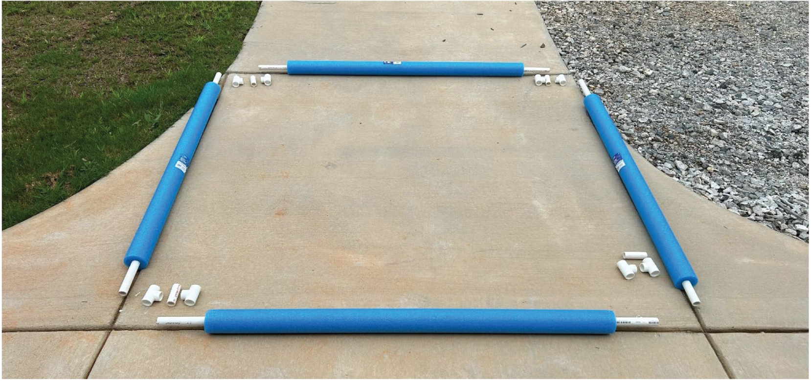
Long Description.
Beginning of the assembly of an obstruction cube. Four PVC pipes covered with blue foam are arranged in a square on a concrete slab with tees and short PVC pieces placed at each corner.
- Connect four 5-foot PVC pipes into a square using ¾-inch PVC tees (Figure B-2). Use 3-inch PVC lengths to connect both PVC tees in the corners. Ensure opposite sides align at the same height.
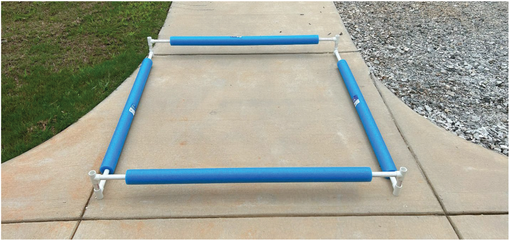
Long Description.
Four PVC pipes covered with blue foam-covered pipes are connected into a square with PVC tees and short PVC pieces forming the corner joints.
- Dry-fit all joints, then disassemble. Clean each end with PVC primer, apply PVC glue to the inside of the tees, and reassemble the corners.
- Repeat the process to create 10 glued squares (for the top and bottom of five obstruction cubes).
- Lay one glued square flat on the ground. Insert a 5-foot PVC pipe into each tee at the corners so that four vertical pipes extend upward (Figure B-3). Do not glue these pipes, to allow for easy disassembly and storage.
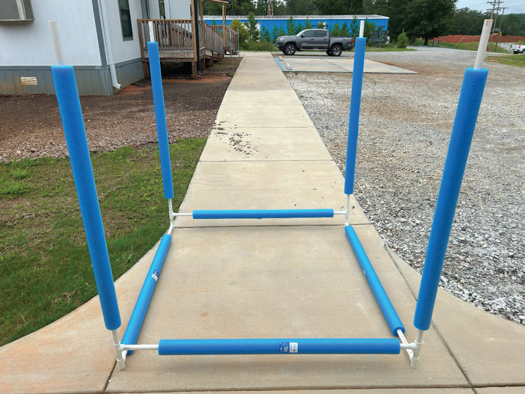
Long Description.
A square PVC frame lies on the ground with four vertical 5-foot pipes covered with blue foam are positioned upright and inserted into the corner tees.
- Attach the second glued square on top, securing the vertical pipes into its corner tees (Figure B-4). Again, do not glue the pipes for easy storage.
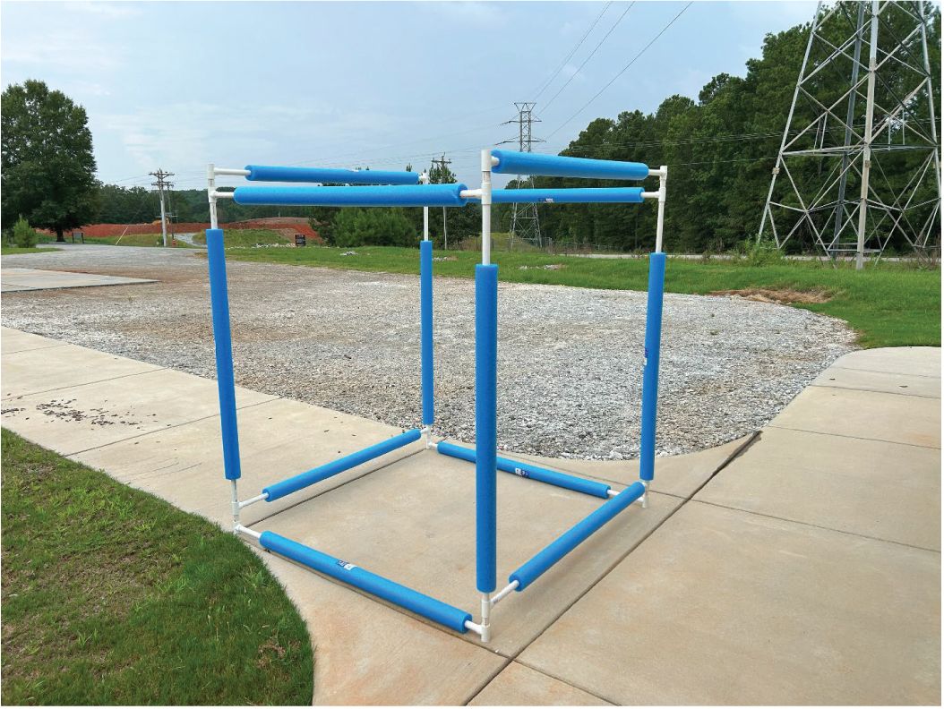
Long Description.
A second PVC square covered with blue foam is secured to the top of the four vertical pipes to form a tall frame.
- Repeat these steps to build four more obstruction cubes.
Step 2: Construct the concrete bucket bases.
- Cut 1- × 4-inch wood boards into twenty 16-inch pieces.
- Using a 1¼-inch hole saw, drill a hole in the center of each 16-inch wood piece.
- Cut twenty pieces of ¾-inch PVC pipe, each 17 inches long.
- Fill each 5-gallon bucket one-third full with dry concrete mix. Add water until the mixture is a stiff paste.
- Insert a 17-inch PVC pipe into the center of the wet concrete. Slide the pipe through the hole in a 16-inch wood piece to help hold it vertically while the concrete sets (Figure B-5).
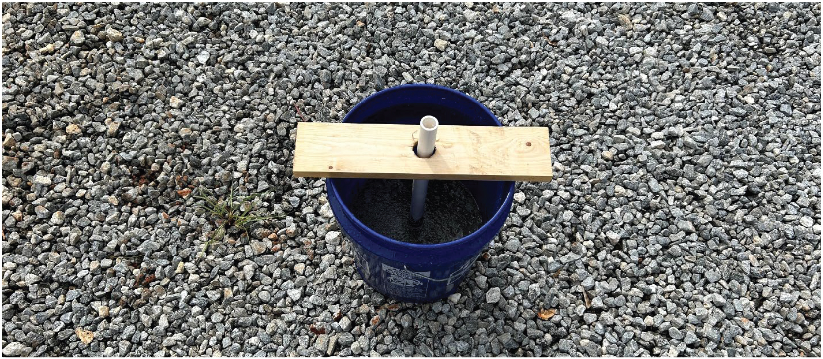
Long Description.
View looking down at a PVC pipe in the center of a bucket of wet concrete held upright by a wood piece with a center hole.
- Repeat for all 20 buckets.
- After allowing the concrete to set for at least 1 hour, clean the exposed end of the vertical piece of PVC with primer and attach a ¾-inch PVC connector with glue. Then attach a 5-foot PVC pipe to each of the connectors (Figure B-6). Do not glue, to allow disassembly for easier storage.
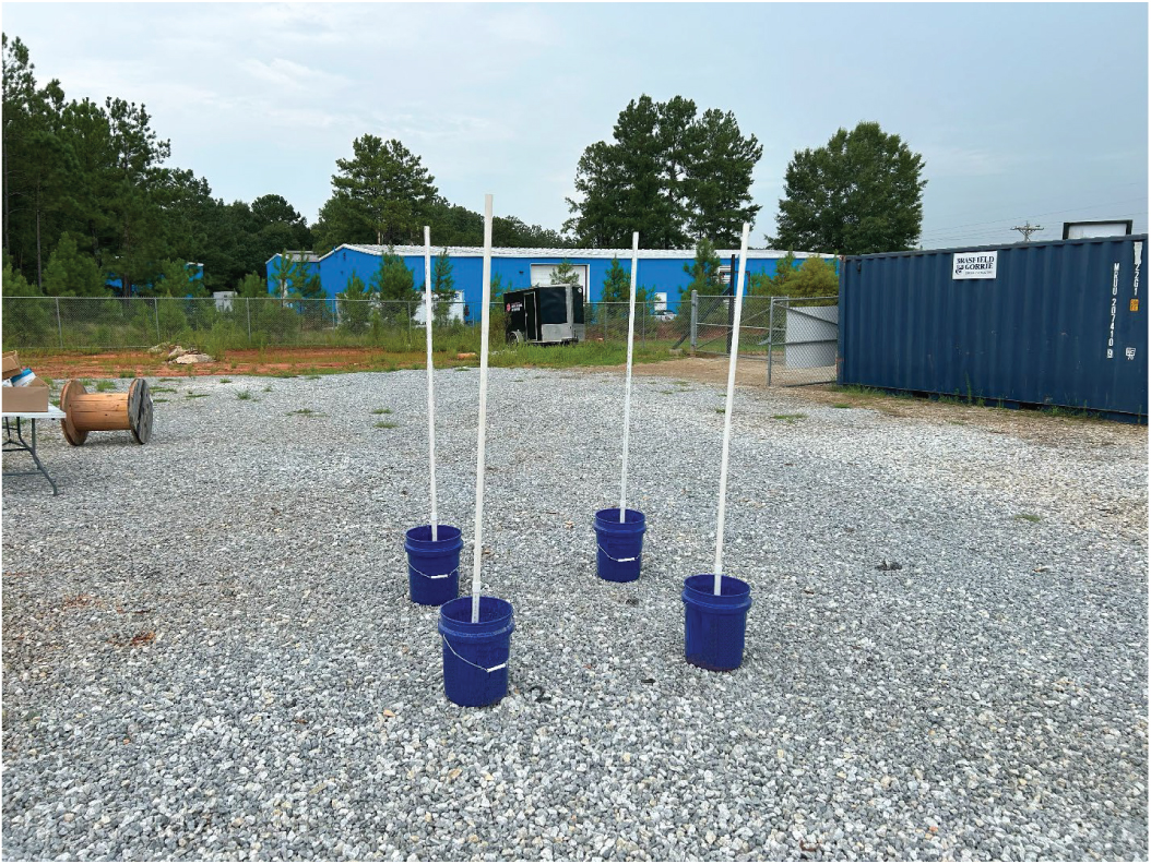
Long Description.
Four buckets with set concrete each hold a vertical PVC pipe topped with a connector and a 5-foot pipe.
Step 3. Setting up the open lane with obstruction cubes.
- Set up the NIST Open Test Lane according to the NIST fabrication guide in Appendix A. This setup assumes an S distance of 10 feet (Figure B-7).
- Arrange four concrete-filled buckets in the corners of a 5- × 5-foot square pattern centered on Bucket Stands 1, 2, and 3.
- Arrange four more concrete-filled buckets in a 5- × 5-foot square pattern to the left and right of Bucket Stand 2, ensuring that the center-to-center distance between them is 10 feet.
- Insert a 5-foot length of PVC pipe into the connector at the top of each concrete-filled bucket.
- Lift each obstruction cube and slide it onto the vertical PVC pipes in the concrete-filled buckets.
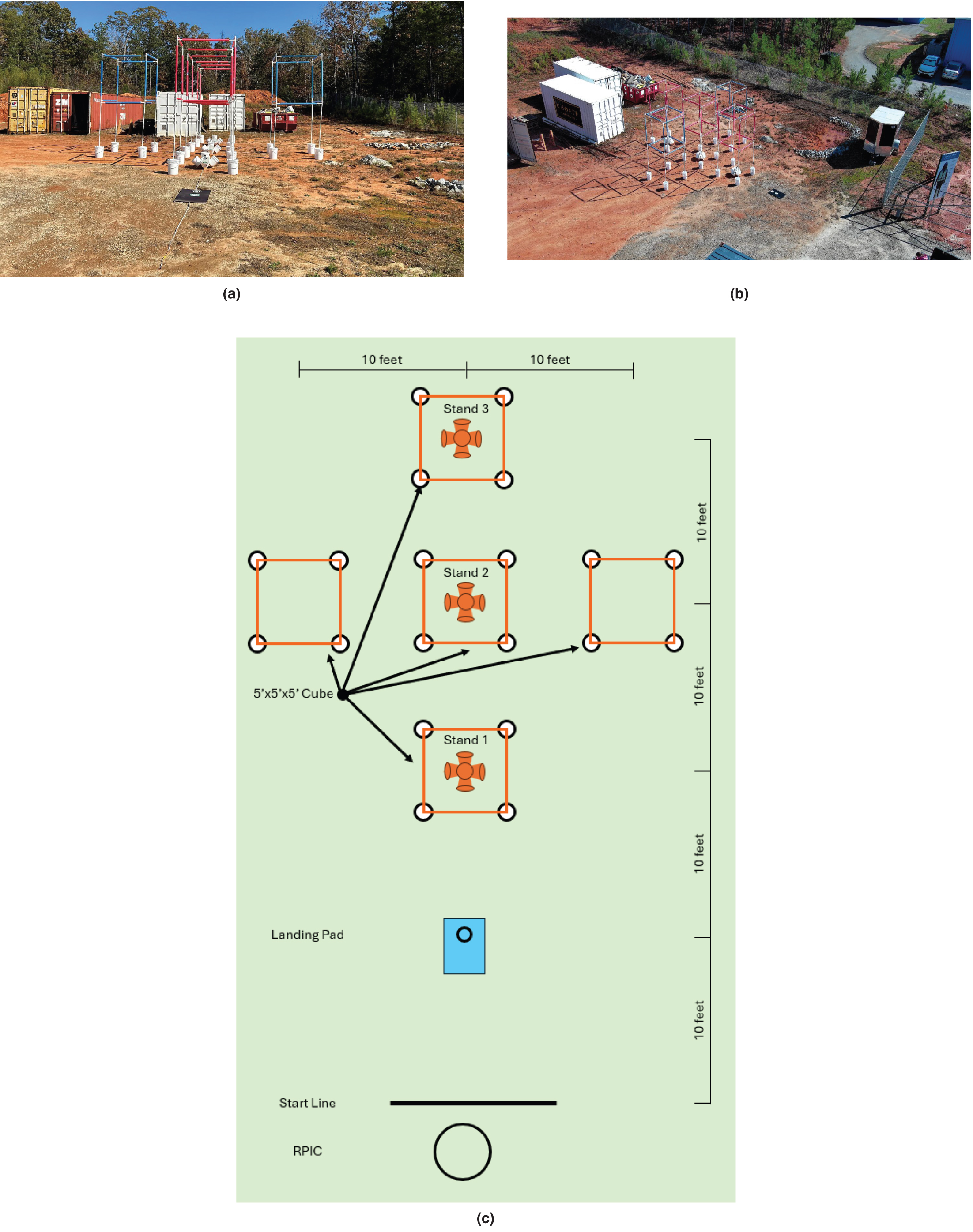
Long Description.
Completed NIST Open Test Lane: (a) Ground view showing three rows of obstruction cubes supported by vertical PVC pipes in concrete-filled buckets. (b) Aerial view showing the five obstruction cubes laid out as a cross. (c) Field diagram of the configuration of the obstruction cubes shows a rectangular field with five identical cube frames arranged in a pattern. Each cube frame is labeled as 5 feet by 5 feet by 5 feet. Three of the cubes contain a bucket stand at the center and are labeled Stand 1, Stand 2, and Stand 3. Stand 1 is located near the lower middle area of the diagram. Stand 2 is above Stand 1, and Stand 3 is above Stand 2 near the top center. Two additional empty cube frames are located to the left and right of Stand 2, so that the overall configuration of the cubes is that of a cross. All cube frames are spaced 10 feet apart horizontally and vertically, as shown by measurement markers on the top and right edges of the diagram indicating 10-foot intervals. Near the lower center of the field is a landing pad marked with a ring symbol. Below the landing pad is a horizontal start line, and below that is a circle labeled RPIC, indicating the position of the remote pilot in command.


