Health and Safety Impacts of Aircraft Cabin Temperatures (2026)
Chapter: 2 Thermal Control in the Aircraft Cabin Environment
2
Thermal Control in the Aircraft Cabin Environment
This chapter addresses thermal control in the aircraft cabin environment both during ground operations and in flight. It begins with an overview of aircraft operating environments and the primary factors that contribute to cabin thermal conditions. The chapter then describes the design requirements for the environmental control system (ECS), relevant regulations and industry standards, and the configuration and operation of the ECS as it relates to thermal management. The discussion then turns to ground-based air conditioning systems used for thermal control while the aircraft is parked at the gate. Finally, the chapter examines the challenges associated with maintaining cabin temperature in both ground and in-flight conditions and discusses operational practices that can be implemented to ensure effective thermal control.
AIRCRAFT OPERATING ENVIRONMENTS
Commercial aircraft operate in a wide range of environments, from virtually any location on earth to altitudes up to 45,000 feet. On the ground, aircraft may be exposed to extreme ambient temperatures, sometimes exceeding 50°C (122°F). Shortly after takeoff—typically within 30 minutes—the aircraft transitions to an external environment that is extremely dry, with water vapor pressure less than 2.4 Pascal (0.00035 pounds per square inch absolute), corresponding to less than 1 percent relative humidity at room temperature. At cruising altitude, outside air temperatures can drop below -55°C [-65°F]) (NRC, 2002), and atmospheric pressure is significantly lower than at sea level—lower than on the summit of Mount
Everest (NRC, 2002). To maintain a safe and comfortable cabin environment under these demanding conditions, the aircraft’s ECS is engineered to manage multiple functions: thermal comfort, air quality, pressurization, and ventilation. The ECS also supports other critical operations such as engine and wing anti-icing and cargo compartment conditioning. These diverse and extreme operating environments place substantial demands on the ECS and related systems responsible for controlling the aircraft cabin’s thermal environment.
CONTRIBUTORS TO THE AIRCRAFT INTERNAL THERMAL ENVIRONMENT
The internal thermal environment of an aircraft is influenced by a combination of both external and internal factors. External factors include:
- Ambient temperature: Aircraft may be exposed to extreme temperatures on the ground, requiring significant heating or cooling to maintain comfort. When aircraft doors are open for catering or boarding, ambient air can enter, causing rapid changes in cabin temperature gradients within the cabin.
- Ambient humidity: High ambient humidity during ground operations can increase the cooling load, while very low ambient humidity at altitude can contribute to drying of the eyes, nose, and skin.
- Solar load: Solar load is the cumulative thermal energy transferred into the aircraft cabin through the aircraft skin and interior windows from the sun’s solar radiation. The higher the solar radiation, the more cooling is required to maintain a comfortable cabin temperature (Giuffrè et al., 2024).
Maintaining comfortable thermal conditions in the aircraft cabin is more challenging during ground operations on hot humid days, when ambient temperatures, humidity, and solar loads can be high, as well as on very cold days.
Additional internal factors influencing the aircraft thermal environment include:
- Occupancy and metabolic heat: Each sedentary passenger generates about 80–100 watts of heat, with higher outputs for more active individuals (Cramer et al., 2022). Flight attendants, due to their activity level, can produce more than double the heat output of a seated passenger. However, because passengers outnumber cabin crew, their collective heat load is significant.
- Heat-generating equipment: Internal equipment, including the in-flight entertainment (IFE) systems, galley equipment for food and beverage preparation, and cabin lighting, all contribute additional heat loads (ASHRAE, 2023). Passenger electronic devices such as laptops and tablets brought into the aircraft as carry-on items and used in flight may also contribute to the heat load. At times, the heat generated by equipment and lighting can be comparable to that produced by passengers and crewmembers.
The aircraft ECS is designed to account for these varying heat loads and, consequently, is often in cooling mode while the aircraft is on the ground and during flight.
AIRCRAFT ENVIRONMENTAL CONTROL SYSTEM AND ITS ROLE IN THERMAL CONTROL
Thermal control systems for the aircraft cabin include both internal and external components. The primary internal system is the aircraft ECS, which operates during both ground and in-flight phases to regulate cabin temperature, ventilation, and air quality. In flight, the ECS is also responsible for pressurizing the aircraft (ASHRAE, 2023; Bezold, 2021). The following subsections describe the design, configuration, and operation of the ECS.
In addition to the ECS, external preconditioned air (PCA) units—ground-based air conditioning systems that may be fixed (e.g., jet bridge–attached units) or mobile (e.g., ground carts)—may be used during ground operations as alternatives to the aircraft ECS. These external systems are particularly important when aircraft are parked at the gate; ground-based air conditioning systems are discussed in detail later in this chapter.
Design and Operating Specifications for Thermal Control on Aircraft
An aircraft ECS is designed to provide a safe, healthy, and comfortable cabin environment (ASHRAE, 2023, NRC, 2002). In particular, the systems are designed to rapidly adjust cabin temperatures under extreme conditions. For example, the ECS can heat a “cold soaked” airplane—one that has been exposed to very low ambient temperatures—to approximately 21–23.8°C (70–75°F) in less than 30 minutes, assuming that there are no passengers or other internal heat loads and that all exterior doors and window shades are closed. Conversely, the ECS can cool a “heat soaked” cabin—one exposed to high ambient temperatures and solar load—to about 23–26.7°C (75–80°F) in less than 30 minutes with no passengers, minimum electrical heat loads, and all exterior doors and window shades closed (ASHRAE, 2023).
A critical factor influencing the cabin thermal environment and the comfort of its occupants is relative humidity. During ground operations, especially boarding, open cabin doors can allow hot and humid outside air to enter the cabin. The ECS is responsible for controlling humidity, which is important not only for occupant comfort and health but also for aircraft safety. High humidity, particularly when combined with elevated temperatures, can cause discomfort. Following a flight when the airplane structure has been cold soaked, high ambient humidity entering the cabin can cause condensation and dripping on the airplane structures. The moisture on the aircraft structures can freeze during the next flight, potentially leading to corrosion. Condensation can also support pathogen growth, which can impact air quality. To mitigate these risks, the ECS removes moisture from the outside air before it enters the cabin, especially while the aircraft is parked on the ground and during low altitude flight (NRC, 2002). Water separators built into the air conditioning packs are specifically designed for this purpose. However, when ground-based systems (e.g., ground carts or airport jet bridge–attached systems) supplying preconditioned (low-pressure) air are used during ground operations (discussed in more detail later in this chapter), the air is supplied downstream of the aircraft’s air conditioning packs. In these cases, cabin humidity is largely determined by ambient conditions, though some condensation and humidity removal may still occur as the PCA cools the incoming air.
During flight, the outside air used for cabin ventilation is very dry, and the humidity within the cabin is primarily a function of the number of occupants and the rate of outside airflow per person. This low humidity (10–20 percent) can cause temporary effects such as dryness of the nose, eyes, and skin for passengers and crewmembers (Nagda and Hodgson 2001; Wyon et al., 2006). The main source of humidity in flight is the cabin occupants, with a smaller contribution from meal and beverage services (ASTM, 2000). At lower altitudes, ambient conditions can influence cabin humidity, and air conditioning packs can remove humidity as needed from the ambient air.
The design of temperature and humidity control systems is informed by a combination of regulatory requirements, industry standards and guidelines, and manufacturers’ operational experiences. Other resources referenced by manufacturers to help establish the design envelope include ambient temperature data in the Integrated Surface Database (NCEI, n.d.) and MIL-HDBK-310, Global Climatic Data for Developing Military Products (DOD, 1997), which provides information on extreme temperatures worldwide that can be used during the design and sizing of ECS (OEM, 2025). The relevant regulations and standards are discussed in the following sections.
Regulations Relevant to the Aircraft Thermal Environment
Current Federal Aviation Administration (FAA) regulations do not specify explicit limits for cabin temperature or other thermal parameters, such as humidity and air speed, under normal operating conditions. Explicit temperature limits are only addressed under improbable failure conditions,1 as discussed below. Instead, thermal design requirements and operational guidance are primarily provided by aircraft manufacturers (discussed in the section that follows), which are influenced by existing standards and regulatory requirements (OEM, 2025).
The design, construction, and operation of commercial aircraft in the United States are regulated under Title 14 of the Code of Federal Regulations (14 CFR). Within 14 CFR, Federal Aviation Regulation § 25.831 addresses ventilation requirements and includes several provisions relevant to the cabin thermal environment (FAA, 1996). Subsection (a) of § 25.831 states:
Under normal operating conditions and in the event of any probable failure conditions of any system that would adversely affect the ventilating air, the ventilation system must be designed to provide a sufficient amount of uncontaminated air to enable the crewmembers to perform their duties without undue discomfort or fatigue and to provide reasonable passenger comfort. For normal operating conditions, the ventilation system must be designed to provide each occupant with an airflow containing at least 0.55 pounds of fresh air per minute.
While not explicitly mentioned, the requirements for crewmembers to perform their duties without undue discomfort or fatigue and the requirements for reasonable passenger comfort would reasonably be interpreted to include thermal conditions.
Subsection (e) of § 25.831 requires that means be provided to enable control of both the temperature and quantity of ventilating air supplied to the flight crew and crewmember compartments.2 Subsection (g) specifies upper temperature limits as a function of flight duration for an improbable failure condition (e.g., loss of all air conditioning packs).3 These upper temperature limits do not apply during normal operation or probable failure conditions.
___________________
1 FAA defines improbable failure conditions as “those failure conditions unlikely to occur in each airplane during its total life, but that may occur several times when considering the total operational life of a number of airplanes of this type. Also, those failure conditions not anticipated to occur to each airplane during its total life but that may occur a few times when considering the total operational life of all airplanes of this type” (FAA, 2011).
2 14 CFR § 25.831(e).
3 14 CFR § 25.831(g).
Additional guidance on complying with FAA regulations in § 25.831 (among others) is provided by Advisory Circular (AC) 25-20. For example, the AC notes that the requirement to provide 0.55 pounds of fresh air per minute per person translates to 10 cubic feet per minute of air at 8,000 feet pressure altitude and at a cabin temperature of 23.9°C (75°F) and that under probable failure conditions, airflow should not fall below 0.4 pounds of fresh air per minute per occupant for periods exceeding 5 minutes (FAA, 1996). Also of relevance, the AC indicates that aircraft “environmental systems should be investigated for the extremes of the airplane operating envelope. Tests (component, sub-system, airplane) and/or analysis should be used to establish the capabilities of the environmental systems at temperatures anticipated to be encountered in service” (FAA, 1996, p. 2).
It is important to note that these requirements in Part 25 are design requirements rather than operational requirements4—they define capabilities that the aircraft must possess, not how those aircraft are to be operated in practice. Nevertheless, design requirements are expected to reflect the intended operational conditions of the aircraft.
Another relevant FAA regulation, § 25.771, states: “Each pilot compartment and its equipment must allow the minimum flight crew (established under § 25.1523) to perform their duties without unreasonable concentration or fatigue.”5 Although this requirement applies specifically to the flight crew and does not explicitly address thermal conditions, thermal environments that result in unreasonable concentration or fatigue would appear to fall within the intent of this requirement. Acknowledging the difference in pilot and flight attendant roles, ensuring that conditions in the cabin do not interfere with flight attendants’ safety-critical duties without unreasonable concentration or fatigue would be similarly important.
Taken together, the implications of § 25.831 and § 25.771 are that the ECS must be designed to provide reasonable passenger thermal comfort during normal and probable failure conditions and to ensure thermal conditions that do not result in unreasonable concentration or fatigue for all crewmembers, including flight attendants.
Industry Standards and Guidelines for Aircraft
The committee identified five aviation industry standards and guidelines relevant to the aircraft cabin environment. While three of these documents primarily address chemical contamination and its role in aircraft air quality, each also includes provisions related to thermal conditions in the cabin or flight deck or both.
___________________
4 14 CFR Part 25.
5 14 CFR § 25.771(a).
The American National Standards Institute/American Society of Heating, Refrigerating and Air-Conditioning Engineers (ANSI/ASHRAE) Standard 161-2023, Air Quality within Commercial Aircraft,6 along with its companion document, ASHRAE Guideline 28-2021, sets forth specific requirements and recommendations for the aircraft’s thermal environment (see Table 2-1) (ANSI/ASHRAE, 2021, 2023a). For example, ANSI/ASHRAE Standard 161-2023 requires minimizing both vertical and horizontal temperature gradients within each temperature control zone.7 These gradients can be influenced by such factors as cabin airflow, seating configuration, IFE, solar load, cooled sidewalls, and air leakage from door seals during flight. In addition to the requirements in Table 2-1, ANSI/ASHRAE Standard 161-2023 also requires the provision of personal air outlets8 (discussed later in this chapter) at each crewmember workstation, jump seat, and crew bunk (ANSI/ASHRAE, 2023a) to allow for localized thermal comfort adjustments. While ANSI/ASHRAE Standard 161-2023 does not detail the derivation of its thermal requirements, it notes that they are based in part on ANSI/ASHRAE Standard 55 and on manufacturer experience (ANSI/ASHRAE, 2023a,b). The relationship between ANSI/ASHRAE Standard 161-2023 and broader thermal comfort standards is discussed further in Chapter 4.
ANSI/ASHRAE Standard 161-2023 also acknowledges the practical challenges of maintaining required thermal conditions on the ground, especially during extreme ambient conditions. Although it does not explicitly exclude such exceedances, it requires airlines to take reporting action in cases of repeated thermal complaints (ANSI/ASHRAE, 2023a).
ASHRAE Guideline 28-2021 is intended as a companion to ANSI/ASHRAE Standard 161. While it does not provide any additional quantitative thermal requirements, it offers qualitative guidance. For example, it notes that cooling and heating loads on the ground are more variable and less predictable than in flight and that additional cooling and heating capacity may be required during ground operations (ANSI/ASHRAE, 2021, 2023a).
The SAE International Aerospace Recommended Practice Report ARP85G, Air Conditioning Systems for Subsonic Airplanes (SAE, 2024a),
___________________
6 As for all American Society of Heating, Refrigerating and Air-Conditioning Engineers (ASHRAE) standards, ANSI/ASHRAE Standard 161-2023 is a consensus document developed by a balanced committee of stakeholders. The designated stakeholder groups for ANSI/ASHRAE Standard 161-2023 include manufacturers (aircraft manufacturers, aircraft subsystem manufacturers, and component manufacturers); owners and operators, including airlines; crewmembers and their unions; and passenger representatives; among others.
7 A temperature control zone is defined as an identified section of the aircraft designed with the capability for independent supply air for temperature control such as between business and economy classes.
8 Small outlets above the seat that can be controlled by the passenger and supply high-velocity air directly to the seat. Also called gasper vents.
TABLE 2-1 Aircraft Cabin Temperature Design and Operating Requirements
| Parameter | Acceptable Conditiona |
|---|---|
| Cabin temperatureb |
|
| Local air speedc |
|
| Temperature spatial variationsd |
|
| Maximum surface temperature differential for seated occupants | Average temperature of sidewall surfacee shall be within 10°F (5.6°C) of the average operative seating area temperature (the average for 4, 24, and 43 in. [100, 610, and 1090 mm] from the floor). Temperature of the floor surface measured at the occupant’s feet shall be within 10°F (5.6°C) of the average operative seating area temperature (the average for 4, 24, and 43 in. [100, 610, and 1090 mm] from the floor). |
| Maximum surface temperature differential in galleys, adjacent to doors | Average temperature of galley sidewall surfacef should be within 10°F (5.6°C) and shall be within 15°F (8.4°C) of the average operative galley temperature measured at 43 in. (1090 mm) from the floor. Average temperature of galley floor surface measured at crew work stations or jumpseats should be within 10°F (5.6°C) and shall be within 15°F (8.4°C) of the average operative galley temperature measured at 43 in. (1090mm) from the floor. |
a See ANSI/ASHRAE Standard 55 for measurement and calculation of operative temperatures in this table.
b Applies to all occupied locations.
c Maximum valued averaged over two-minute period. Occupant acceptability of a given air velocity will vary with supply air temperature. Draft-sensitive body areas are the ankles and the neck.
d Includes the region 2 in. (50mm) or more from the sidewalls, between 4 in. (100 mm) and 43 in. (1.1 m) above the floor in seating areas, and between 4 in. (100 mm) and 67 in. (1.7 m) in aisles and galleys. These requirements shall apply when the personal air outlet nozzles are closed.
e Sidewall temperature measured at ankle, waist, and head levels: 4 in. (100 mm) (or at the lowest practical location on the sidewall), 24 in. (0.6 m), and 43 in. (1.1 m) from the floor.
f Sidewall temperature measured at ankle, waist, and head levels: 4 in. (100 mm), 43 in. (1.1 m), and 67 in. (1.7 m) from the floor.
NOTE: PAO = personal air outlet.
SOURCE: ©ASHRAE, www.ashrae.org. (2023) ASHRAE Standard-161-2023.
provides guidelines and recommendations for subsonic airplane air conditioning systems and components, including requirements, design philosophy, testing, and ambient conditions. This guideline was referenced by manufacturers of narrow- and wide-body aircraft, in addition to regional aircraft (OEM, 2025).
The SAE International Aerospace Information Report 4766, Air Quality for Commercial Aircraft Cabins, provides information on the engineering aspects of ECS design needed to achieve acceptable air quality in commercial aircraft cabins (SAE, 2024b). However, the temperature section of this document primarily references and summarizes the relevant federal regulations discussed earlier in this chapter, rather than establishing independent quantitative requirements.
It is important to note that industry standards such as those developed by ANSI/ASHRAE and SAE are voluntary. They become mandatory only if a relevant regulatory authority, such as the FAA, formally adopts them, incorporates their provisions into regulatory requirements, or includes them as part of the aircraft certification process. As of this writing, the FAA has not formally adopted the standards discussed in this section, but it acknowledges that manufacturers may use these standards and handbooks to support the design and certification of the ECS.
Configuration and Operation of the ECS9
The aircraft ECS is responsible for conditioning and distributing pressurized air to meet requirements for ventilation, thermal comfort, and cabin pressurization. In conventional transport aircraft, supply air is extracted from the propulsion system and undergoes staged cooling and pressure regulation before being delivered to the flight deck and passenger cabin. The following section describes the principal ECS components and operation for maintaining thermal comfort.
During flight, the engine compressors pressurize outside air to a high temperature—typically between 170°C and 350°C (340–660°F)—with pressures ranging from 2 to 10 atmospheres (ANSI/ASHRAE, 2021) (step 1 in Figure 2-1 below). The high-pressure air, known as “bleed air,” is drawn from the engines upstream of the combustor (see Figure 2-2 for a typical
___________________
9 Descriptions in this section of ECS components and operation are for typical commercial aircraft, applying to those that fall in narrow-body and wide-body classes as well as regional jets. It should be understood, however, that aircraft models differ in their thermal control systems and some details may not apply to every specific aircraft model. ECS configurations and operation for turboprop aircraft were not specifically considered as no (or almost no) such aircraft continue to be used in Part 121 operations (see Appendix A), although the committee acknowledges that air carriers outside the United States continue to operate these aircraft models.
bleed air system). The bleed air is cooled with ambient air through the airplane’s precooler heat exchangers to about 175°C (350°F) (NRC, 2002). The cooled bleed air is then supplied to the air conditioning packs (step 2 in Figure 2-1), where it is further cooled to a temperature typically between 10°C and 18°C (50–65°F). The temperature is set to meet the needs of the temperature control zone requiring the most cooling—usually the flight deck or a densely occupied economy cabin. Air conditioning packs consist of valves, turbines, heat exchangers, and compressors which work together to cool the air to the required temperature for provision to the aircraft (see Figure 2-3 for a schematic of a typical air conditioning pack). An exception to the traditional engine bleed system is the Boeing 787, which uses electrically driven compressors to provide and condition outside air, without use of the engine compressors (Subramanya et al., 2024).
After conditioning, the air from the air conditioning packs is combined with recirculated cabin air that has been drawn through high-efficiency particulate air (HEPA) filters in the mix manifold (steps 3 and 4 in Figure 2-1). HEPA filters can also include carbon-based adsorption layers, which are standard on some aircraft models (e.g., Boeing 787) and available as options on others (Zhang et al., 2022). The mixed air is then supplied to the cabin through overhead nozzles that run the length of the cabin, typically on both sides. Larger aircraft may have two air distribution nozzles per side to ensure even airflow (step 5 in Figure 2-1).
Before entering the cabin, the supply air can be heated further with trim air—additional bleed air added downstream of the air conditioning packs. This allows for independent, fine temperature control in each cabin zone, providing for lower-density seating zones that require warmer supply air for passenger comfort.
Newer aircraft are equipped with smart ECSs that dynamically adjust airflow to match occupant density, meeting regulatory requirements (14 CFR § 25.831(a)) and improving airplane performance during flight and hot ground operations and in high-density seating configurations.
A visualization of the aircraft air distribution system is provided in Figure 2-4. Clean supply air flows continuously into the cabin and is exhausted via return air grilles that run along both sides of the cabin, typically where the sidewalls meet the floor. Approximately half of the exhaust air is recirculated through the HEPA filters (and, if equipped, carbon filters), while the other half is expelled from the aircraft through an outflow valve located near the tail, which also helps maintain cabin pressure (step 6 in Figure 2-1).
Auxiliary Power Unit as an Air Supply Source for the ECS
During ground operations, aircraft require energy to power onboard systems. While the aircraft ECS can use the engine compressors for this

SOURCE: The Boeing Company, 2020. Copyright © 2020 Boeing. All rights reserved.

NOTES: Figure shows compressor extraction points, pressure regulation and shutoff, temperature control via a precooler, and distribution to pneumatic users. Arrows depict the flow of air through the bleed-air system, leading to the air conditioning packs (see Figure 2-3).
SOURCE: The Boeing Company (2001). Copyright © 2026 Boeing. All rights reserved.

NOTE: Figure illustrates air-cycle cooling, moisture removal, recirculation, mixing, and zonal temperature control.
SOURCE: ©ASHRAE www.ashrae.org (2019).
purpose, it is more common—especially when engines are not running—for the onboard auxiliary power unit (APU) to be used. The APU is a small gas turbine engine, typically located in the tail cone of the aircraft. Its primary function is to provide the power necessary to start the main aircraft engines, but it can also be used to continuously supply electrical power for onboard systems (such as avionics) and deliver high-pressure, high-temperature air to the air conditioning packs to meet heating and cooling needs while the aircraft is on the ground (NRC, 2002). An aircraft’s pilot or qualified maintenance personnel can activate the APU.
Cabin Temperature Control Zones
Cabin temperature is managed through multiple temperature control zones, which can be adjusted by the pilot using an overhead panel dial in the flight deck (see Figure 2-5 for an example). These controls typically provide qualitative guidance—such as a dial ranging from “cold” (or “C”)

NOTE: Figure shows the overhead air supply, lateral circulation within seating rows, floor-level air return for heat, and contaminant removal in the occupied zone.
SOURCE: The Boeing Company, 2020. Copyright © 2020 Boeing. All rights reserved.

NOTE: C = cold; W = warm.
SOURCE: The Boeing Company, 2026. Copyright © 2026 Boeing. All rights reserved.
to warm (or “W”)—rather than specifying exact temperatures. The typical selectable range for cabin temperature is approximately 18.3°C to 29.4°C (65–85°F) (ASHRAE, 2023). Importantly, it is not possible to similarly manage humidity levels independently in an aircraft.
Commercial aircraft are divided into multiple temperature control zones. There is a separate zone for the flight deck and typically two to eight temperature zones in the passenger cabin, depending on the aircraft model. Cargo bays and crew rest areas may also be configured as a separate temperature control zone (ASHRAE, 2023). Larger aircraft generally have more zones; for example, the Airbus A380 and Boeing 777X can each have up to 16 temperature control zones (OAT, 2023). During flight, the pilot typically sets the cabin temperature dial to Auto for cabin comfort, but further adjustments can be made as needed. Some aircraft are equipped with additional temperature controls at the flight attendant station, allowing flight attendants to adjust settings for specific zones as needed (A4A, 2026). On some aircraft, personal airflow outlets, commonly known as air gaspers, allow passengers additional thermal control. These small air outlet nozzles, located above each seat, supply high-velocity air which passengers can direct and adjust in quantity, though not in temperature. Depending on the
aircraft model, the air supply for these personal airflow outlets may come directly from the air conditioning system, from recirculated air, or from the general air distribution system (NRC, 2002). Personal airflow outlets are optional features and therefore may not be available on every aircraft.
The response time for temperature changes in the cabin is relatively quick, due to the high air exchange rate and cooling capacity of modern aircraft. Typically, an aircraft achieves an outside air exchange rate of 10 to 20 air exchanges per hour, and a total air exchange rate (including HEPA-filtered recirculated air) of 20 to 30 per hour. This enables rapid cooling or heating of the cabin. As part of certification, commercial aircraft are subjected to “cold soaked” and “heat soaked” tests, in which the aircraft is placed in extremely cold (-32°C, or -25°F) or extremely hot (above 46°C, or 115°F) environments and must demonstrate the ability to reach comfortable temperatures within 30 minutes (ASHRAE, 2023).
Systems for Monitoring Cabin Temperatures
Aircraft typically have one to two temperature sensors in each temperature control zone, located in the overhead ceiling panel or upper sidewall panels. These sensors provide feedback to the air conditioning packs, which in turn adjust the supply air temperature to maintain the selected cabin zone temperature based on control panel settings in the flight deck or, if installed, at the flight attendant control panel.
Some aircraft are equipped to continuously record cabin temperature data both in flight and on the ground, allowing for later download and analysis. For example, Boeing 777 and Airbus A350 aircraft feature quick access recorder (QAR) capabilities. However, not all commercial aircraft have this functionality (A4A, 2026), and a QAR does not capture humidity data, which, as discussed in later chapters, are critical for assessing the potential health and safety impacts of cabin temperatures. Monitoring humidity levels with current aircraft equipment requires the installation of dedicated humidity sensors and the use of portable data loggers (OAT, 2023).
Battery-operated data loggers may be temporarily installed in various cabin locations to gather temperature and humidity data for purposes other than routine monitoring (e.g., research, troubleshooting). These devices allow for rapid characterization of cabin thermal conditions over multiple flights, with data available for later review and assessment (NRC, 2002). However, such installations are typically temporary and require the airline to verify that the installation meets the requirements of all applicable regulations. Prior to installation, airlines may seek to obtain a No Technical Objection letter from the aircraft manufacturer on technology for which they lack detailed data before obtaining approval from the regulator.
Additionally, the data logger may need to undergo electromagnetic interference testing to ensure that it does not interfere with airplane electrical systems (such testing determines if the device emits signals that could disrupt other equipment) (FAA, 2017).
GROUND-BASED AIR CONDITIONING SYSTEMS FOR THERMAL CONTROL OF AIRCRAFT
During ground operations, thermal control of cabin temperature is essential for efficient aircraft turnaround, as it serves to support the safety and comfort of crewmembers and service personnel as well as passengers. According to a 2010 FAA report, active heating is needed when ambient temperatures fall below 7.2°C (45°F), and active cooling is needed when ambient temperatures rise above 10°C (50°F) (FAA, 2010), reflecting the narrow range of ambient temperatures in which cabin thermal comfort can be maintained without conditioning of the air supply.
In designing an aircraft ECS, manufacturers seek to optimize fuel efficiency, weight, payload, range, and environmental performance. As a result, the ECS reflects a series of trade-offs among environmental performance, system weight, power consumption, and aircraft range and is designed to accommodate the vast majority of expected ambient operating conditions. Designing the system to meet the most extreme possible conditions would require additional capacity, which would increase weight and reduce aircraft range and overall performance. Under normal in-flight operating conditions and throughout the certified flight envelope10 (including the vast majority of expected ambient operating conditions based on statistical environmental conditions), the ECS meets safety requirements and typically maintains thermal comfort. However, during extreme hot-weather ground conditions, when ECS performance is inherently less effective, the availability of ground-based sources of conditioned air is important for supplementing the onboard ECS.
A variety of ground-based air conditioning systems are available to provide supplemental heating, cooling, and ventilation of aircraft when an onboard ECS cannot operate or is not in use. These include:
- Airport centralized PCA system: These systems supply conditioned air from a central plant to the aircraft at the gate.
- Low-pressure ground carts and jet bridge PCA systems: Jet bridge PCA units are located beneath the jet bridge and can be ground- or bridge-mounted (see Figure 2-6) (NASEM, 2019). Along with
___________________
10 The flight envelope is defined as the bounds within which a certain aircraft can operate, commonly depicted with a graphic representation of these bounds that shows the interrelationships of the different operational parameters (NRC, 1997).

SOURCE: Hearshe/stock.adobe.com
- low-pressure portable PCA units, they provide conditioned air directly to the aircraft’s air distribution system downstream of the air conditioning packs (NASEM, 2012; NRC, 2002). PCA units reduce the need for aircraft to operate their APUs (or engines) during ground operations—a preferred outcome, as APU operation consumes fuel, generates emissions, increases noise, and adds to maintenance costs while the aircraft is parked.
- High pressure ground carts: These units connect to the aircraft via high-pressure ground connections and deliver high-pressure, high-temperature air upstream of the aircraft’s air conditioning packs (Bezold, 2021, NRC, 2002).
Responsibility for supplying, operating, and maintaining PCA units varies depending on such factors as equipment type (e.g., mobile versus fixed) and gate ownership model (airline-owned or -leased versus shared or common gates). PCA units may be owned, operated, and maintained by airports, airlines, or their contractors (NASEM, 2012, 2019). In some cases, equipment owned by the airport might be maintained by airlines. These differing arrangements can complicate efforts to ensure consistent equipment availability, reliability, and performance, particularly when PCA units are relied on for thermal control (NASEM, 2019), as discussed later in this chapter.
CHALLENGES WITH THERMAL CONTROL ON AIRCRAFT
The following sections outline the challenges associated with maintaining optimal thermal control in aircraft, both during ground operations and in flight. This discussion begins with a high-level review of available data on thermal complaints, with a more detailed analysis provided in Chapter 5.
Frequency of Equipment Issues that Contribute to Thermal Complaints
Table 2-2 presents system failure data related to the aircraft thermal environment, extracted from reports collected by the National Aeronautics and Space Administration (NASA) Aviation Safety Reporting System (ASRS) over 35 years (1990 to February 2025) and from reports submitted to the Association of Flight Attendants’ (AFA’s) 2Hot2Cold app over 7 years (2018–2025). Details on the committee’s data collection methods can be found in Appendix A.
The NASA ASRS data reviewed by the committee include 154 reports submitted between 1990 and 2025 of issues with the aircraft thermal environment that could impact occupant health and safety; all but eight were heat related. Of the 132 reports mentioning one or more equipment
| Equipment System | Frequency (ASRS) N=132 a | Percentage of Reports Specifying One or More Equipment Issues (ASRS) | Frequency (2Hot2Cold) N=1,217 a | Percentage of Reports Specifying One or More Equipment Issues (2Hot2Cold) |
|---|---|---|---|---|
| ECS/Pack | 75 | 56.8% | 118 | 9.7% |
| APU | 18 | 13.6% | 759 | 62.3% |
| PCA unit | 5 | 3.8% | 131 | 10.8% |
| Multiple b | 34 | 25.8% | 209 | 17.2% |
NOTES: FAA SDRS data not presented because analysis of those data was limited to ECS mechanical issues. APU = auxiliary power unit; ECS = environmental control system; PCA = preconditioned air.
a N represents the number of reports for which one or more equipment issues was indicated. For NASA ASRS reports, 22 of 154 committee-identified reports did not specify a contributing equipment issue, and 3,462 of the 4,679 2Hot2Cold reports did not specify a contributing equipment issue.
b The majority of ASRS and 2Hot2Cold reports noting multiple equipment contributors to cabin temperature issues involved a combination of APU and PCA equipment problems.
contributors to cabin temperature issues, approximately 29 percent noted issues with ground-based air conditioning systems (alone or in combination with other equipment issues), while more than half involved the ECS. Among ECS system failures, about 87 percent were related to air conditioning packs, 11 percent to the bleed system, and 2 percent to other components. Analysis by flight phase shows that cabin temperature events were most common during ground operations (mentioned in 65 percent of reports). Regardless of the type of equipment issue, prevalence was highest during the summer, with fewer incidents reported in spring and fall (see Figure 2-7). Data on ECS mechanical malfunctions obtained from an analysis of reports describing cabin temperature issues from FAA’s Service Difficulty Reporting System (SDRS) show a similar seasonal pattern, with malfunctions in the cabin temperature control system (trim system, cabin temperature sensors) and the cabin cooling system (air conditioning packs) reported most frequently (FAA, 2026).
In contrast, ECS issues were less commonly reported in the 2Hot2Cold dataset among those reports that mentioned a contributing equipment issue. The most frequently reported problems were with the APU—inoperable or not activated—followed by reports of multiple simultaneous equipment issues, most of which involved both the APU and PCA units. These findings

NOTES: Winter = December–February; Spring = March–May; Summer = June–August; Fall = September–November. APU = auxiliary power unit; ECS = environmental control system; PCA = preconditioned air.
SOURCE: Created with data from NASA (2025).
underscore the importance of having an operable APU and/or PCA unit with sufficient capacity to manage cabin temperatures during ground operations, particularly on days with elevated ambient temperatures.
The difference in emphasis on pack malfunctions among the three datasets may reflect the distinct purposes of these three reporting systems. NASA ASRS is intended for reporting serious safety issues and may be more likely to capture urgent in-flight ECS malfunctions; FAA SDRS is intended to capture mechanical malfunctions, defects, and failures on aircraft and focuses on hazards rather than specific incidents; and the 2Hot-2Cold app is designed to collect reports of cabin temperatures that become uncomfortably too warm or too cold. Notably, the majority of 2Hot2Cold reports—89 percent of the nearly 5,000 reports—were submitted by cabin crew (AFA, 2025). Both the ASRS and 2Hot2Cold datasets are discussed in greater detail in Chapter 5.
Challenges with Thermal Control During Flight
This section addresses the challenges that may arise with maintaining thermal control during flight. In some cases, the issues with aircraft systems described here can also impact thermal control during ground operations.
Air Conditioning Packs
Air conditioning pack issues (inoperable, deferred maintenance, or malfunction in flight) were reported in more than 50 percent of the NASA ASRS reports of cabin-temperature-related incidents for which a specific equipment issue was noted. Commercial aircraft used in Part 121 operations are equipped with a minimum of two air conditioning packs to condition the air supplied to the airplane cabin. This redundancy is a key safety feature; if one pack fails, the aircraft can continue to operate with the other. Depending on the aircraft model and the air carrier’s approved maintenance program, the FAA permits operation with a deferred11 pack for up to 10 days (as specified in the master minimum equipment list, or MMEL);12 if the pack is not repaired within that period, the aircraft must be removed
___________________
11 When a piece of equipment that needs repair is “deferred,” this refers to deferred maintenance and means that for a specified period of time the aircraft can be operated without repairing the equipment.
12 MMEL is an FAA-approved document that specifies which equipment can be inoperative for a flight, allowing operational flexibility while maintaining airworthiness (FAA, 2023). For example, if an aircraft’s air conditioning pack fails, the aircraft MMEL allows for 10 days to repair the failed pack starting the day after failure. An FAA-approved air carrier’s MEL is derived from the MMEL. Airlines use maintenance tracking systems, maintenance control oversight, and daily MEL status reports to track days remaining (Pilot Institute, 2025).
from service. When a pack is inoperative, the remaining pack operates at a higher airflow setting, which may reduce overall cooling capacity on some models (FAA, 2023). Although simultaneous failure of both packs during flight is quite rare, several ASRS reports noted cases where aircraft were dispatched with an inoperative pack and the second pack malfunctioned in flight, resulting in an emergency that required rapid descent and landing due to a loss of cabin pressure and temperature control. Although uncommon, such scenarios underscore the risks associated with deferred maintenance of air conditioning packs, particularly during extreme ambient temperatures that may add additional workload to the remaining pack.
When an aircraft is deplaned and reboarded quickly in a hot climate, there may be insufficient time to connect PCA units or high-pressure ground carts at the gate, making it difficult to sufficiently cool the cabin. As a result, hot cabin temperatures can persist after takeoff. However, when ECS systems are functioning properly, the cabin typically cools to the setpoint in about 15 minutes or less, due to high air exchange rates and robust cooling capacity.
To ensure optimal performance and thermal control, aircraft manufacturers recommend that dedicated maintenance tasks for air conditioning packs be carried out prior to the start of the summer season (OEM, 2025). These tasks include cleaning the heat exchangers (clogging limits airflow and heat removal) and checking system components such as flow control valves and water drainage. Issues related to ECS performance of aging aircraft and maintenance programs are discussed in Box 2-1.
Cabin Air Distribution
Optimizing air distribution in an aircraft cabin to provide a comfortable thermal environment for both sedentary passengers and active flight attendants, who have different thermal needs, is a significant challenge for ECS engineers. Achieving air distribution patterns that deliver cooler supply air through the aisles, maintain reasonable uniformity among passengers, and minimize drafts is also an important consideration in designing the aircraft air distribution system. These considerations apply to both in-flight and ground operations.
A practical challenge arises when debris, dust, and other matter are deposited into the air supply ducting. For example, over time, the yellow hoses used to provide conditioned air from the PCA unit to the aircraft (see Figure 2-6) can deteriorate and shed small pieces of plastic, which may enter the aircraft air distribution system and interfere with airflow and optimal ECS functioning (NASEM, 2019). Addressing such issues requires replacing the PCA hose and cleaning the air distribution system to remove foreign debris and other accumulated matter. To minimize this risk, airlines
BOX 2-1
ECS Performance Degradation and Maintenance for Aging Aircraft
ECS performance degradation over time is an expected consequence of aircraft aging and harsh operating conditions and can result in reduced efficiency (A4A, 2026) even if the ECS remains functional (i.e., serviceable). Examples of factors that can contribute to decreased efficiency include filter clogging, leakages, and wear and tear of moving parts such as seals and bearings. Some aircraft manufacturers report taking ECS equipment degradation into account in system design, and all emphasize the importance of routine maintenance (e.g., heat exchanger cleaning, filter replacement) (OEM, 2025). As noted by one manufacturer, ECS components (with few exceptions such as filters) are generally not life-limited by design, meaning that their performance is not a function of age or flight hours. Rather, their functional lifetime is determined by their condition and the effectiveness of maintenance activities (including repair and replacement) to keep the system performing as designed (OEM, 2025). Thus, proper maintenance of the aircraft ECS is critical to ensuring adequate thermal control, particularly during extreme weather conditions.
Aircraft manufacturers provide recommendations on routine maintenance tasks to operators via an aircraft maintenance manual and may also issue service letters or bulletins. Airlines have dedicated departments that track airplane in-flight and ground performance to ensure proper maintenance and airplane operation. These departments keep detailed records of any issues, including any maintenance conducted or needed. Additionally, many aircraft models have built in monitoring and diagnostic systems that monitor parameters of ECS performance in real time, alerting crew of possible degraded operational modes (e.g., blocked valves, sensor failures) that can inform troubleshooting and maintenance activities (OEM, 2025).
As the primary regulator for aviation safety, FAA establishes requirements for a continuous airworthiness maintenance program (FAA, 2016). A key element of such a program is the establishment of a continuing analysis and surveillance system (CASS), which air carriers are required to do under Title 14 Part 121, § 121.373. Air carriers use the CASS to monitor, analyze, and optimize the performance and effectiveness of their aircraft maintenance and inspection programs (FAA, 2016). A CASS can be used to identify trends, recurring defects, and systemic weaknesses and to guide the identification and implementation of corrective actions. A reliability program that has been accepted and authorized for use by FAA can fulfill some CASS requirements related to operational data collection, analysis, and corrective action (FAA, 2018).
may install metal screens on the airplane ground service intake. Periodic inspection and cleaning of the air distribution system, as needed, help identify issues (e.g., clogging, leakages) and ensure proper performance (OEM, 2025).
Simple operational measures can also improve ECS performance. For example, closing window shades and limiting the use of cabin electrical systems (such as IFE and galleys) can significantly reduce the heat load in the cabin. Additionally, the use of personal air outlets (on equipped aircraft) is encouraged to increase air movement in the vicinity of passengers and cabin crew, which enhances thermal comfort through localized cooling (OEM, 2025).
Cabin Air Recirculation
As described earlier in this chapter, the rates of cabin cooling and heating are also influenced by the aircraft’s air recirculation systems. Recirculation fans contribute to thermal control in two ways: one, by increasing the effective air supply through the combination of filtered recirculated air with conditioned pack air and, two, by promoting mixing within the cabin. However, as specified in the MMEL, aircraft are permitted to operate for a limited period—typically up to 10 days—with a recirculation fan inoperative, provided that certain conditions are met, such as proper functioning of the air conditioning packs. Manufacturers recommend that replacement of recirculation fans be expedited when operating in high or low temperatures in order to ensure optimal thermal control and passenger comfort (OEM, 2025).
Challenges with Thermal Control During Ground Operations
This section discusses challenges unique to thermal control in aircraft during ground operations. As noted previously, issues with air conditioning packs, cabin air distribution, and recirculation systems can also impact thermal control on the ground, but these topics are not repeated here.
Aircraft time at the gate (turnaround time) can vary widely depending on aircraft size, type, route, airline type (e.g., regional, low cost),13 and airport. Smaller aircraft with quick turnaround times may be parked at the gate for as little as 20 minutes, while larger passenger aircraft can remain
___________________
13 Different airline types may use different infrastructure during ground operations. For example, regional and value airlines may use airstairs for boarding instead of more expensive jetways, which can have implications for access to ground-based air conditioning systems used for cabin temperature control and reliance on APUs. For example, one value airline that responded to the committee’s information request indicated that the APU is used 95 percent of the time for cabin temperature during ground operations (AVA, 2025).
parked at the gate for several hours. Unexpected delays can further extend turnaround times (NASEM, 2019; Wignall, 2022).
During ground operations, the ramp area14 is often crowded with various types of ground support equipment and vehicles, including PCA units, baggage tugs, catering vehicles, fueling trucks, lavatory-servicing equipment, and deicing vehicles (NASEM, 2019). This high density of activity can contribute to ramp-traffic congestion, which is an important consideration for effective use of ground-based air conditioning systems.
The majority of hot cabin complaints occur while aircraft are on the ground (parked at the gate or on the taxiway), particularly during summer months (see Figure B-5 in Appendix B for supporting data). While on the ground, aircraft may become heat- or cold-soaked, further complicating thermal control. To provide a comfortable cabin temperature before boarding, preconditioning the aircraft (cooling or heating of the cabin) is recommended by manufacturers and airlines (A4A, 2026; OEM, 2025). The aircraft’s APU or a PCA unit can be used for this purpose. When problems with these systems are not detected right away or require additional personnel (e.g., aircraft mechanics or ground crew) to be called to the aircraft to address the issue, exposures of cabin occupants to hot or cold temperatures may be extended.
Auxiliary Power Unit
Upon landing, the APU is typically activated by pilots when ambient temperatures exceed the capabilities of the PCA system, when the PCA is not adequately sized for the specific aircraft model, or when a PCA is unavailable (e.g., due to maintenance issues or remote parking locations). Interviews with airline and airport staff conducted during a previous National Academies study found that APU usage is virtually continuous during periods when ambient temperatures at the ramp exceed PCA design limits—conditions that can persist for 3 months or more in some regions (NASEM, 2019). The importance of a functioning APU for maintaining thermal comfort under these circumstances is clear. Airlines may also direct pilots to use the APU during short ground times (turnarounds), typically when the servicing interval between flights is less than a specified threshold (e.g., 30 to 45 minutes). The FAA estimates that, on average, APUs are used for about 7 minutes per airplane turn—2 minutes upon arrival at the parking position and approximatively 5 minutes prior to pushback (NASEM, 2019). However, this average encompasses all flights and does
___________________
14 The ramp, also called an apron, is an area of the airport where planes park and are serviced (RDU, 2014).
not reflect the extended usage that may be required during extreme temperature conditions.
In some cases, APU-related challenges can arise due to malfunctions. The APU is included on the aircraft’s MMEL, which allows an aircraft to be operated for an FAA-approved period (up to 10 days) without a functioning APU, provided certain conditions are met. These conditions may include the requirement that the engine backup AC power system is operational and that the flight remains within 180 minutes of a suitable airport (OEM, 2025). In other situations, the APU may be fully functional but not used. Reasons for non-use include the absence of pilots to operate the APU, fuel-saving initiatives, or, in some locations, prohibitions on APU use due to noise or environmental emissions concerns. Many airports—particularly those outside the United States—have enacted policies restricting APU operations to reduce noise and emissions from the APU turbine engine (NASEM, 2019).
Engines During Low Power Setting
When an aircraft is taxiing under its own power—often using a single engine to conserve fuel—the engines operate at a low power setting. At these low settings, the engines may not provide sufficient bleed air pressure to ensure full airflow to the cabin. As a result, the cabin may not receive adequate ventilation or temperature control solely from the engines during taxi. To address this, the APU is often operated during taxi to provide the necessary airflow for cabin comfort and environmental control (Ahmed et al., 2021; Mickeviciute, 2023).
Ground-Based Air Conditioning Systems at Airports
Many airports are equipped with ground-based systems, such as PCA units, to supply conditioned ventilation air to aircraft while they are parked at a gate. However, these systems are not always available for use (Heiple, 2025; NASEM, 2019). When ground-based systems are unavailable, the aircraft must rely solely on its APU or engines to provide the required air to the airplane ECS for thermal control. Quantitative data on the relative use of APUs and each type of PCA as sources of conditioned air supply during ground operations are not available (A4A, 2026).
Even when ground-based air conditioning systems are available, they may not always be used or may not function properly. The decision to connect and use PCA units is influenced by several operational considerations, including:
- Fuel-saving initiatives: Airlines may prioritize reducing fuel consumption by limiting the use of the APU.
- Aircraft turnaround times: Short ground times may lead ground staff to perceive that there is insufficient time to connect PCA units before the next flight.
- PCA unit availability: Equipment may be in use elsewhere, out of service, or otherwise unavailable.
- Staffing and training: Limited staff capacity, competing operational priorities, or insufficient training can delay or prevent proper PCA unit hookup (NASEM, 2019).
Equipment malfunctions, often resulting from maintenance problems, mishandling, or neglect, are another common challenge (Levenson, 2024). For example, kinked (depicted in Figure 2-8) or deteriorated hoses can significantly reduce the cooling capacity of PCA units (A4A, 2026). Hoses can become damaged by being continuously dragged across pavement or run over by ground support equipment vehicles on the ramp (NASEM, 2019). The resulting tears can give rise to air leaks. Some airports have upgraded their PCA hoses to hose reels (see Figure 2-9) or hose management systems that dispense the hose in a manner designed to minimize kinking and the risk of being run over. Regular inspection and maintenance are important to ensure that PCA units are in good working order.
Ground crews—whether airline or airport employees or third-party contractors—are responsible for operating ground-based air conditioning systems and ensuring their proper connection to the aircraft. These crews are critical actors in maintaining effective thermal control and overall

SOURCE: Scorsone (2025), used with permission from Air Line Pilots Association.
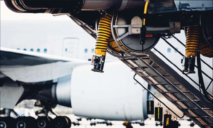
SOURCE: iStock.com/Fabian Gysel.
aircraft operations. In addition to physically connecting and operating the equipment, ground crews communicate with pilots and airport staff regarding the status and functionality of PCA units. However, airport and airline stakeholders report that high turnover among ground crew employees is common. The frequent turnover can result in a workforce with less overall experience and limited familiarity with the proper operation of specialized equipment. One of the most frequently cited challenges to optimal system usage is the misuse of, and subsequent damage to, PCA units by users (NASEM, 2019). Such misuse—often stemming from inadequate training or lack of experience—can lead to equipment unavailability and operational disruptions.
Long delays in obtaining spare parts—whether due to low inventory or the discontinuation of component production—can contribute to system unavailability and hinder the use of PCA units. This issue is particularly pronounced at airports with aging PCA units and ground power equipment, where sourcing compatible parts may be especially challenging (NASEM, 2019).
A study from the Airport Cooperative Research Program of the National Academies Transportation Research Board identified both challenges and opportunities for improvements in the use of PCA units during ground operations. One suggested solution for addressing PCA unit usage challenges was the development and implementation of a real-time monitoring
system to track the operational status of the gate equipment—including whether equipment is actively in use, faulty, undergoing maintenance, or idle. Such a system would provide valuable, actionable information to airport and airline operators, enabling more effective system optimization and improved management of the cabin thermal environment (NASEM, 2019).
Even when PCA units are available and functional, there may be inherent limitations in their cooling capacity, which can affect their ability to deliver the necessary volume of airflow at the required temperature. These limitations are often exacerbated on larger aircraft with higher passenger densities and during periods of hot and humid weather. One of the more frequently reported challenges to effective PCA unit usage—according to both airport and airline staff—occurs when ambient temperatures exceed the design standards of the PCA system (NASEM, 2019). In such cases, the PCA unit may be unable to sufficiently condition the aircraft cabin, whether the outside air is too hot or too cold for the system’s capabilities. This underscores the importance of designing, sizing, and maintaining PCA units to accommodate typical climatic conditions (NASEM, 2019), taking into consideration changing temperature norms and the frequencies of extreme temperature events.
Specifications for PCA units are available through industry organizations (e.g., the International Air Transport Association’s Air Handling Manual 974) and can inform both the design of equipment as well as requirements for procurement purposes. The provision by aircraft manufacturers of detailed specifications for PCA unit sizing for a given aircraft model—for example, through airport planning manuals (see, for instance, The Boeing Company, 2024)—can also help airports and airlines procure PCA units that meet thermal control needs during ground operations.
SAE’s Aircraft Ground Support Equipment committee is actively investigating potential improvements to PCA procedures and performance during ground operations. Its current efforts include the development of aircraft recommended practices documentation (ARP6986) that will address minimum performance requirements and design parameters for PCA units to guide PCA manufacturers, the International Air Transport Association, and airline operators. Although this committee was unable to review the draft standard, the SAE website reports that it will cover performance and maintenance requirements for PCA filtration and hose assemblies and digital communication between PCA units and the aircraft cabin (SAE, 2026). Additionally, ARP6986 will address the interface installation requirements for a sensor unit that can be installed on aircraft to measure temperature, relative humidity, and other relevant parameters and provide real-time feedback to PCA units.
CONCLUDING REMARKS
In summary, this chapter has outlined the key factors influencing thermal control in the aircraft cabin both during ground operations and in flight, described the governing ECS design requirements and standards, detailed the configuration and operation of ECS components relevant to thermal management, and examined the role of ground-based air conditioning systems in maintaining cabin conditions during ground operations. The chapter also reviewed the primary challenges associated with temperature control across operational phases and highlighted airline and airport practices that promote effective thermal regulation. These considerations provide the foundation for the following conclusions:
Conclusion 2-1: In the vast majority of circumstances, aircraft ECS, as currently designed, can maintain comfortable cabin temperature both in flight and during ground operations when the ECS and APU are fully operational and used appropriately. During periods of extreme ambient temperatures, maintaining comfortable cabin temperatures during ground operations may require temporary operational adjustments, such as preconditioning the cabin, turning off IFE systems, and closing window shades.
Conclusion 2-2: The selection of conditioned air supply during ground operations is influenced by such factors as equipment availability, aircraft ground time, ambient conditions, and local constraints. Reliance on APUs and high-pressure ground air carts is generally less desirable than the use of PCA units because of higher fuel consumption, noise, maintenance impacts, and, in some settings, regulatory limitations. This underscores the importance of adequate PCA sizing for both airflow and cooling capacity as well as of the reliability and proper use of PCA when employed for thermal control.
Conclusion 2-3: Thermal issues may arise in flight when an ECS system component (e.g., air conditioning pack, bleed system) fails and the aircraft is dispatched in accordance with the air carrier’s MEL. On the ground, cold or hot cabin temperatures can also occur when the APU is inoperative or not operated, either due to the absence of authorized operators or to restrictive airport rules that prevent its use. Additionally, when an aircraft is relying on a PCA unit, factors such as insufficient heating or cooling capacity, equipment outages, damaged hoses, or improper hookup can all contribute to inadequate cabin heating or cooling. Operational best practices can help address these common contributors to cabin temperature issues.
Conclusion 2-4: Allowances to operate aircraft with an inoperative APU or air conditioning pack in accordance with an air carrier’s MEL are commonly described in safety and complaint reports as contributing to challenges with hot or cold aircraft cabins, particularly during periods of extreme ambient temperatures.
Conclusion 2-5: Across both ground and in-flight phases, challenges related to excessively hot or cold cabin temperatures often reflect not a single failure, but a combination of environmental conditions, equipment limitations, and operational practices. Understanding these interacting factors is essential for identifying opportunities to prevent temperature-related health and safety impacts and for informing strategies to improve thermal management in aircraft cabins.
REFERENCES
A4A (Airlines for America). 2026. Information request for airlines: NASEM Study on Health and Safety Impacts of Aircraft Cabin Temperatures. Document provided to the Committee on Health and Safety Impacts of Aircraft Cabin Temperatures on February 4, 2026. Available by request through the National Academies’ Public Access Records Office.
AFA (Association of Flight Attendants). 2025. 2HOT2COLD data through 2025-07-31 redacted for NAS. Document provided to the Committee on Health and Safety Impacts of Aircraft Cabin Temperature on September 9, 2025. Available by request through the National Academies’ Public Access Records Office.
Ahmed, U., F. Ali, and I. Jennions. 2021. A review of aircraft auxiliary power unit faults, diagnostics and acoustic measurements. Progress in Aerospace Sciences 124:100721.
ANSI/ASHRAE (American National Standards Institute/American Society of Heating, Refrigerating and Air-Conditioning Engineers). 2021. Guideline 28-2021. Air quality within commercial aircraft. Peachtree Corners, GA: ANSI/ASHRAE. https://pdfbooksite.com/wp-content/uploads/2026/02/ashrae-guideline-28-2021-free.pdf (accessed March 16, 2026).
ANSI/ASHRAE. 2023a. Standard 161-2023: Air quality within commercial aircraft. Peachtree Corners, GA: ANSI/ASHRAE.
ANSI/ASHRAE. 2023b. Standard 55-2023: Thermal environmental conditions for human occupancy. Peachtree Corners, GA: ANSI/ASHRAE.
ASHRAE. 2023. Chapter 13: Aircraft. https://www.ashrae.org/file%20library/technical%20resources/covid-19/si_a19_ch13.pdf (accessed March 11, 2026).
ASTM (American Society for Testing and Materials). 2000. Air quality and comfort in airliner cabins. ASTM STP 1393. West Conshocken, PA: ASTM.
AVA (Association of Value Airlines). 2026. Information request for airlines: NASEM Study on Health and Safety Impacts of Aircraft Cabin Temperatures. Document provided to the Committee on Health and Safety Impacts of Aircraft Cabin Temperatures on February 6, 2026. Available by request through the National Academies’ Public Access Records Office.
Bezold, A. 2021. Cabin air quality—Key to a comfortable flight. https://www.aircraft.airbus.com/sites/g/files/jlcbta126/files/2021-08/FAST-article-Cabin-air-Jan-2021.pdf (accessed May 7, 2025).
The Boeing Company. 2001. Schematic representation of a typical aircraft engine bleed-air system.
The Boeing Company. 2020. Airplanes 201: The airplane cabin environment. https://ir.enterair.pl/wp-content/uploads/2020/05/Boeing-Airplane-Cabin-Recirculation.pdf (accessed May 20, 2026).
The Boeing Company. 2024. 757-200/-300 airplane characteristics for airport planning. https://www.boeing.com/content/dam/boeing/v2/airports/acaps/757_Rev_H.pdf (accessed May 1, 2026).
The Boeing Company. 2026. Representative flight-deck interfaces from Boeing 737 aircraft showing flight crew controls for cabin and flight-deck temperature setpoints used to manage thermal comfort.
Cramer, M. N., D. Gagnon, O. Laitano, and C. G. Crandall. 2022. Human temperature regulation under heat stress in health, disease, and injury. Physiological Reviews 102(4):1907–1989.
DOD (Department of Defense). 1997. Department of Defense handbook: Global climatic data for developing military products. MIL-HDBK-310. June 23. https://cvgstrategy.com/wp-content/uploads/2013/08/MIL-HDBK-310.pdf (accessed May 1, 2026).
FAA (Federal Aviation Administration). 1996. Pressurization, ventilation, and oxygen systems assessment for subsonic flight including high altitude operation. Advisory circular no. 25-20. https://www.faa.gov/documentLibrary/media/Advisory_Circular/AC_25-20.pdf (accessed March 12, 2026).
FAA. 2010. Voluntary airport low emission program technical report. DOT/FAA/AR-04/37. Office of Airports, Airport Planning and Programming. https://www.faa.gov/sites/faa.gov/files/airports/resources/publications/reports/vale_techreport_v7.pdf (accessed March 16, 2026).
FAA. 2011. System safety analysis and assessment for Part 23 airplanes. Advisory circular no. 23.1309-1E. https://www.faa.gov/documentLibrary/media/Advisory_Circular/AC%2023.1309-1E.pdf (accessed March 11, 2026).
FAA. 2016. Air carrier maintenance programs. Advisory circular no. 120-16G. https://www.faa.gov/regulations_policies/advisory_circulars/index.cfm/go/document.information/documentID/1028859 (accessed May 7, 2026).
FAA. 2017. Use of portable electronic devices aboard aircraft. Advisory circular no. 91.21-1D. https://www.faa.gov/regulations_policies/advisory_circulars/index.cfm/go/document.information/documentid/1032206 (accessed May 7, 2026).
FAA. 2018. Reliability program methods—Standards for determining time limitations. Advisory circular no. 120-17B. https://www.faa.gov/regulations_policies/advisory_circulars/index.cfm/go/document.information/documentid/1035253 (accessed May 7, 2026).
FAA. 2023. Development and use of an operator’s MEL, NEF program, and CDL for operations under 14 CFR Parts 91K, 121, 125, and 135. Advisory circular no. 120-125. https://www.faa.gov/documentLibrary/media/Advisory_Circular/AC_120-125.pdf (accessed March 6, 2026).
FAA. 2026. Summary of Service Difficulty Reporting System (SDRS) database. Document provided to the Committee on Health and Safety Impacts of Aircraft Cabin Temperatures on January 14, 2026. Available by request through the National Academies’ Public Access Records Office.
Giuffrè, A., P. Colonna, and C. De Servi. 2024. Dynamic thermal model of passenger aircraft for the estimation of the cabin cooling and heating requirements. Applied Thermal Engineering 244:122641.
Heiple, S. 2025. Presentation at Committee on Health and Safety Impacts of Aircraft Cabin Temperature meeting 2 (virtual), August 21. Guidance for requesting available at https://www8.nationalacademies.org/pa/managerequest.aspx?key=HMD-HSP-24-18.
Levenson, M. 2024. Amid oppressive heat, broiling airplane cabins add to travelers’ woes. The New York Times, July 12, A13. https://www.nytimes.com/2024/07/11/weather/extremeheat-planes-flying-airlines.html (accessed March 17, 2026).
Mickeviciute, R. 2023. Auxiliary power unit (APU): The unsung hero of aviation safety. AeroTime. July 1. https://www.aerotime.aero/articles/apu-the-unsung-hero-of-aviation-safety (accessed April 6, 2026).
Nagda, N. L., and M. Hodgson. 2001. Low relative humidity and aircraft cabin air quality. Indoor Air 11(3):200–214.
NASA (National Aeronautics and Space Administration). 2025. ASRS database online. https://asrs.arc.nasa.gov/search/database.html (accessed March 11, 2026).
NASEM (National Academies of Sciences, Engineering, and Medicine). 2012. Airport ground support equipment (GSE): Emission reduction strategies, inventory, and tutorial. Washington, DC: The National Academies Press.
NASEM. 2019. Optimizing the use of electric preconditioned air (PCA) and ground power systems for airports. Washington, DC: The National Academies Press.
NCEI (National Centers for Environmental Information). n.d. Global hourly—Integrated Surface Database (ISD). National Oceanographic and Atmospheric Administration. https://www.ncei.noaa.gov/products/land-based-station/integrated-surface-database (accessed May 1, 2026).
NRC (National Research Council). 1997. Aviation safety and pilot control: Understanding and preventing unfavorable pilot–vehicle interactions. Washington, DC: National Academy Press.
NRC. 2002. The airliner cabin environment and the health of passengers and crew. Washington, DC: The National Academies Press.
OAT (Online Aviation Training). 2023. Boeing 777 air systems. https://oat.aero/2023/11/28/boeing-777-air-systems/ (accessed March 6, 2026).
OEM (Original Equipment Manufacturers). 2025. Aggregated and deidentified manufacturer responses: Documents provided to and compiled by the Committee on Health and Safety Impacts of Aircraft Cabin Temperatures. Available by request through the National Academies’ Public Access Records Office.
Pilot Institute. 2025. What is the minimum equipment list (MEL)? https://pilotinstitute.com/what-is-mel/ (accessed March 6, 2026).
RDU (Raleigh-Durham International Airport). 2014. Where the planes park: Ramp vs. tarmac vs. apron. https://www.rdu.com/where-the-planes-park-ramp-vs-tarmac-vs-apron/ (accessed March 6, 2026).
SAE (SAE International). 2024a. ARP85G—Air Conditioning Systems for Subsonic Airplanes. https://www.sae.org/standards/arp85g-air-conditioning-systems-subsonic-airplanes (accessed May 15, 2026).
SAE. 2024b. AIR4766—Air Quality for Commercial Aircraft Cabins. https://www.sae.org/standards/air4766-air-quality-commercial-aircraft-cabins (accessed May 15, 2026).
SAE. 2026. ARP6986—Aircraft ground support requirement for maintenance and operation of preconditioned air units (PCA) and passenger boarding bridge (PBB) supplying air to the cabin. https://www.sae.org/standards/arp6986-aircraft-ground-support-requirement-maintenance-operation-preconditioned-air-units-pca-passenger-boarding-bridge-pbb-supplying-air-cabin (accessed March 6, 2026).
Scorsone, A.-M. 2025 (unpublished). ALPA Health and Environment Working Group (HEWG), Cabin Air Quality SME. Air Line Pilots Association, International. Guidance for requesting available at https://www8.nationalacademies.org/pa/managerequest.aspx?key=HMD-HSP-24-18.
Subramanya, S., J. Aleksandar, C. Xavier, S. Rebholz, and F. Tong-Yette. 2024. 2024–01–08, 2024–01–12. Review of the commercial aircraft environmental control systems: Historical developments to the current state of the art. Paper presented at AIAA SCITECH 2024 Forum, Orlando, USA. https://arc.aiaa.org/doi/abs/10.2514/6.2024-2815 (accessed March 16, 2026).
Wignall, A. 2022. How it works: The aircraft turnaround. AeroTime. https://www.aerotime.aero/articles/32767-how-it-works-the-aircraft-turnaround (accessed April 6, 2026).
Wyon, D. P., L. Fang, L. Lagercrantz, and P. O. Fanger. 2006. Experimental determination of the limiting criteria for human exposure to low winter humidity indoors (RP-1160). HVAC&R Research 12(2):201–213.
Zhang, X., J. Liu, X. Liu, C. Liu, and Q. Chen. 2022. HEPA filters for airliner cabins: State of the art and future development. Indoor Air 32(9):13103.


