Improving Information for Social Policy Decisions -- The Uses of Microsimulation Modeling: Volume II, Technical Papers (1991)
Chapter: Model Specification
the context of building microanalytic simulation systems: CASE (computer-assisted software engineering) and object-oriented programming.59 Both have direct applicability to the issue of model specification. Several other examples of how current software engineering can assist in building the next generation of microanalytic simulation modeling systems are discussed below.
Model Specification
Model specification is at the heart of using microanalytic simulation models. Indeed, in reviewing the history of the TRIM2 system as well as others such as MASH, model specification soon becomes the major software issue as the models simulated evolve and become more complex. Increasing complexity of the model is a necessary and useful development in that real world administrative rules and policy proposals are complex; models that represent reality must track the existing or proposed complexity in order to be useful.
Unfortunately, complexity increases over time, and the resulting computer programs that represent the substance of the model can become quite difficult to manage. While such a computer code may have been well structured during the model’s initial development, it often loses such structure as layers of changes are made. This can lead to a situation in which the program cannot be understood without the cadre of technical intermediaries that have developed, refined, and modified the model over its lifetime. Thus, while a computer simulation system may have all of the operating characteristics and alternatives in it that are needed, it may be unusable by someone who is new to the system. Such a condition of dependence stymies the system’s growth and makes it unlikely that it will be usable in any location other than its original home.
To some extent TRIM2 has undergone such a process. The Urban Institute maintains a staff of technical people who understand the inner workings of the model and who are called on to make any necessary modifications and perform many of the experiments for which TRIM2 is used. This position of a near monopoly of knowledge was not purposely created; rather, it is the result of an initial design that did not foresee a need for an easily exportable product and easy-to-use interface that would allow the model to be modified and used easily by others. The situation was exacerbated by a pattern of external funding that emphasized investments on the margin rather than allowing more general redesign; in such circumstances the model grew over time by accretion rather than by periodic restructuring when appropriate. In this sense a microanalytic simulation system may be regarded as a piece of embodied vintage capital; it
represents the software technology available at the time of its construction and suffers increasingly from the limitations of that technology over time.
Microanalytic models of the TRIM2, DYNASIM, and SPSD/M class are complex in that a significant part of their value derives from the wealth of institutional detail that they contain.60 Such models evolve over time and extend their usefulness by incorporating the code for simulating new administrative and policy proposals and new legislation as it is approved. Since the older legislation and policy initiatives form a baseline for analysis of the changes, the old code is retained, leading to a moderate but continuous process of growth in the overall computer-based system.
Programs implementing microanalytic models for simulation are efficient in specifying such models to the extent that changes in the models can be made relatively easily and preferably by persons who are not computer specialists.61 Thus, changes in input data, generally in the form of parameters, are preferred to changes in the computer program itself, which can be quite complex with substantial interdependencies that are not apparent to the casual user.
Extensive parameterization of computer-based simulation systems has been an effective solution in providing flexibility in specializing models within the context of a more general system for simulation.62 In addition to allowing specific numbers such as tax rates to be specified at simulation start time, binary (0–1) parameters can be used to specify the structure of a model by allowing certain modules or subprograms to be executed while inhibiting the execution of others. These binary parameters act as on-off switches embedded in the flow of control of the simulation program. The extent to which such a strategy can work depends on the extent to which the need for such switches is recognized at the time the program is written.
Present simulation systems implementing microanalytic models do not provide substantial flexibility at the user or black box level for modification of model structures. At the programming or glass box level, such flexibility may exist; however, as simulation systems grow in size and complexity, such changes become much trickier and more dangerous to attempt. Such limitations on model specification at the user level limit interest in and demand for the use of such current models.
Current microanalytic simulation models use a subroutine, or line-oriented
code paradigm, for their construction and structure. We suggest that a visual paradigm is more appropriate in that it would allow the model builder and user to construct, observe, and manipulate the model at levels that are more intuitive and understandable.
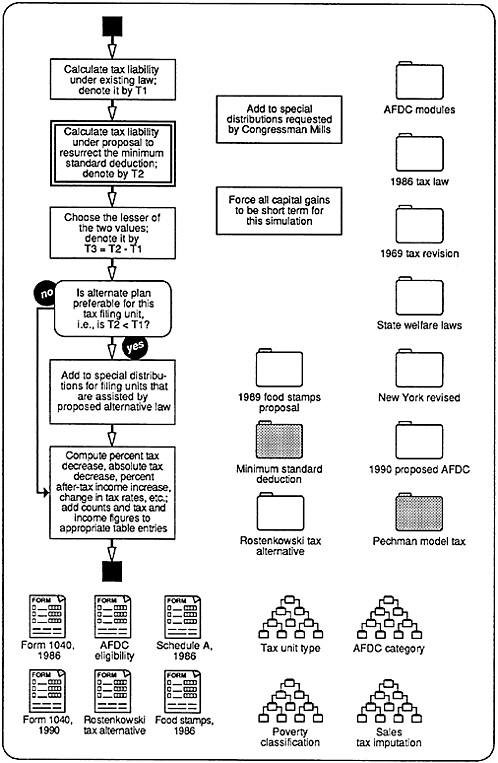
Recently developed CASE techniques should be able to provide substantial assistance in the near future.63 For example, consider the possibility of building a microanalytic simulation model graphically, using a flow chart paradigm for all levels except the bottom layer for actual code and control information. Further, suppose that the purpose of the simulation model is to ascertain the effect of a new minimum standard deduction in the U.S. federal individual income tax structure and to compute the distribution of taxes under existing law and proposed altered law. The overall flow chart for the simulation might appear as in Figure 2.
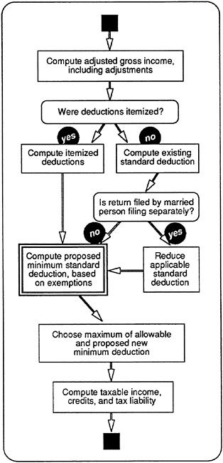
Suppose now that the flow chart could be constructed from objects that appear on a modeler’s palette of icons or, alternatively, are stored in similar form in a modeler’s library.64 Further suppose that each of the higher-level icons could be expanded into a flow chart using lower-level icons by, say, the click of a mouse and that such a procedure could be performed recursively until the bottom layer is reached. Thus, in this example, clicking on the box in Figure 2 with the thick outline would result in the screen displayed in Figure 3. Note the additional modules and other icons on the desktop; any of them could be invoked by dragging them into the flow chart and attaching appropriate connectors. In fact, Figure 3 illustrates the process of model construction proceeding upon what might be regarded as a microsimulator’s workbench. Similarly, the heavily outlined box in Figure 3 could be exploded at the click of a mouse to yield Figure 4.
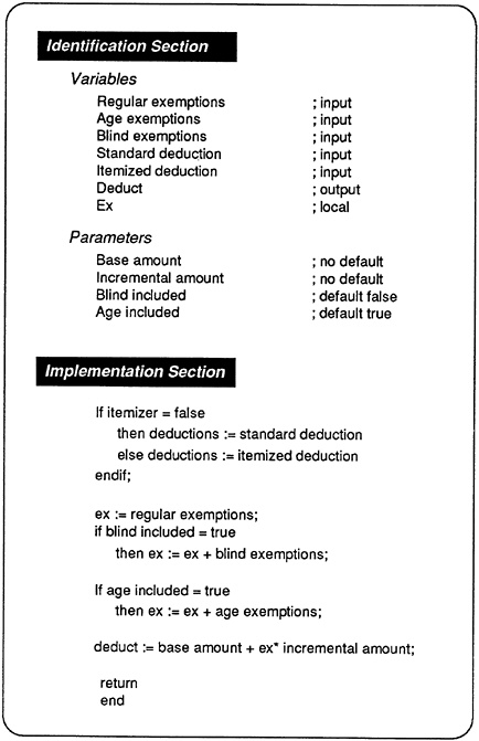
The final or bottom layer is different. It would contain two sections: identification information used to ensure consistent linking of the module to other modules in the model and the actual code representing semantic meaning of the box description one level up. Thus, in this example, clicking on the box in Figure 4 with the heavy outline would lead to a display such as Figure 5.

FIGURE 2 Overall flow chart for a microsimulation tax model.
All windows, including the code window, would be modifiable by a user with appropriate privileges.65,66
When an appropriate model has been put together, a user could invoke it by means of a command that would assemble the appropriate code fragments, using the nested flow charts as the basis for what gets assembled in what order and incorporating the tools corresponding to the different objects available for model construction.67 Libraries of routines for housekeeping and the more technical aspects of the simulation process would be built by professional programmers associated with model development, which less sophisticated users could take for granted in their use of the model structure.68
This is basically a construction kit approach to the creation of microanalytic simulation models but embedded in a more general environment. The environment includes a library function set in a windowing environment, specialized objects that can be used to advantage in constructing models, the ability to modify objects at various depths, and the ability to hide information through nesting for simplicity as appropriate.69
The approach to supporting microanalytic simulation activities is hypothetical only in that it shows all of the pieces of such an environment functioning together as a coherent whole. In fact, most if not all of the individual pieces required exist today in moderately sophisticated forms. While the existing pieces were produced independently and would be difficult if not impossible to integrate now, it is not difficult to conceive of near-term software developments that would make such an integrated system feasible within a few years and certainly by 1995.
It is interesting to note that the construction-kit-oriented approach is already being used in a variety of applications, both serious and for entertainment. For example:
Music Works70 and similar computer-based music composition systems provide a kit of elements or objects with which to create scores. The objects have visual meaning to the user (notes of various duration, sharps, flats, rests)
and can be placed within other objects having substantive meaning (scores, measures, keys). Once the kit has been used to construct the model, it can be activated (or simulated), resulting in music.
National Systems Lab View software provides a kit of objects that are laboratory instruments simulated on the computer. Instruments can include analog-digital converters that interface the computer-based experiment control with external instrumentation. The user configures the instruments and connections appropriately for the experiment and can then activate (or perform simulations) using the system.71
The Pinball Construction Set72 provides a user with a set of elements, or objects, with which to create different pinball machines. The objects have visual meaning and are familiar (flippers, bumpers, traps). Characteristics of the physical environment may be changed (acceleration constant, gravity, weight of ball), and the activated simulation obeys the current environmental settings.73
MacInTax74 provides a model of the individual income tax filing process. The user is presented with a set of dynamic forms and underlying pop-up worksheets that continuously recompute tax liability as new information is entered. The user is given a comprehensive set of form objects corresponding to current law and can create auxiliary objects as required.75
The simulation language Simscript II, which originated in the 1960s, now has a graphical user interface with which to define queuing models.
Stella and Extend, both programs for defining simulation models, use a building block approach and graphical object representations for defining stocks and flows and for activating simulations using the models thus defined.
NextStep provides a set of objects for input and output associated with a NeXT process (sliders, numerical dials or potentiometers, gauges, strip recorders). These objects can be “wired” and manipulated to execute tasks directly. These tasks can display a graphic portrait of their activity as they execute.


