Stainless Steel Strands for Prestressed Concrete Bridge Elements (2025)
Chapter: 5 Research Findings and Products

CHAPTER 5
Research Findings and Products
5.1 Stainless Steel Prestressing Strand Characteristics
Properties of low-relaxation SS prestressing strands used for design may be taken as the minimum properties specified in ASTM A1114/A1114M, which include the following:
- Minimum tensile strength, fpu: 240 ksi based on the nominal area of the strand.
- Nominal diameter: 0.52 or 0.62 in. with nominal areas of 0.167 and 0.231 in.2, respectively.
- Minimum yield strength, fpy: 90% of fpu.
- Minimum ultimate tensile strain, εpu: 0.014.
- If more precise data are not available, the modulus of elasticity for stainless steel prestressing strand, based on the nominal cross-sectional area of the strand, may be taken as Ep = 24,000 ksi.
Where the properties of the SS prestressing strands are known for a project, the properties reported by the manufacturer may be used.
5.1.1 Deviation of Pretensioned Strands
Based on tests and analyses performed as part of this study, pretensioned SS prestressing strands may be deviated using devices that have been successfully used for conventional carbon steel prestressing strands.
5.2 Stress Limitations for Stainless Steel Prestressing Strands
Based on the experimental results and analysis of the bridges in the reliability design space performed for this project, the stresses in the SS prestressing strand immediately prior to the transfer of prestress and at the service limit state shall not exceed the values specified in Table 17.
Pretensioned members with SS prestressing strands may be designed for a prestressing strand tensile stress immediately prior to transfer of up to 0.75 fpu if all limit states are satisfied and it can be demonstrated that the member exhibits adequate ductility.
5.3 Prestress Losses
5.3.1 Prestress Relaxation Loss
The relaxation of SS prestressing strands was determined from tests conducted in this study. Based on the results of one million-hour tests, equations for relaxation at different prestress levels have been determined in Table 18.
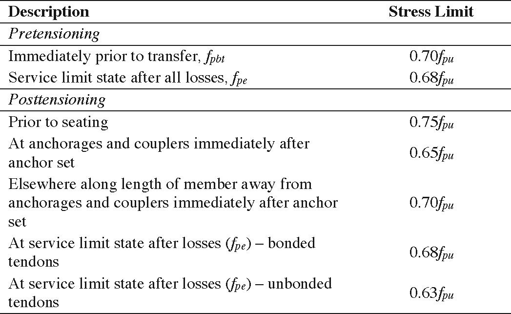
Long Description.
The table presents stress limits for stainless steel prestressing strands under pretensioning and post-tensioning conditions. Under pretensioning, the stress limit is 0.70 times f sub p u immediately prior to transfer, labeled as f sub p b t, and 0.68 times f sub p u at the service limit state after all losses, labeled as f sub p e. Under post-tensioning, the stress limit prior to seating is 0.75 times f sub p u. At anchorages and couplers immediately after anchor set, it is 0.65 times f sub p u. Elsewhere along the length of the member away from anchorages and couplers, it is 0.70 times f sub p u immediately after anchor set. At the service limit state after losses, the stress is 0.68 times f sub p u for bonded tendons, labeled as f sub p e, and 0.63 times f sub p u for unbonded tendons, labeled as f sub p e.
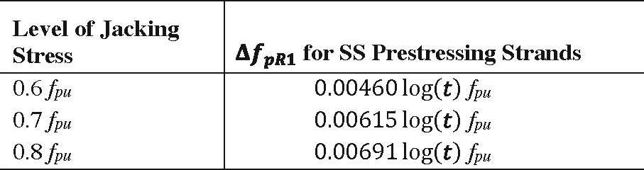
Long Description.
The table presents equations for relaxation losses, denoted as delta f sub p R 1, for stainless steel prestressing strands tensioned to three different jacking stress levels. For a level of 0.6 times f sub p u, the relaxation loss is 0.00460 times log of t times f sub p u. For a level of 0.7 times f sub p u, it is 0.00615 times log of t times f sub p u. For a level of 0.8 times f sub p u, it is 0.00691 times log of t times f sub p u.
A general equation was also developed to predict the relaxation loss for SS prestressing strands for initial prestress levels from 0.6fpu to 0.8fpu based on the measured tensile strength of the strand. The total prestress loss from relaxation of the SS strand (ΔfpR1) may be determined as:

Long Description.
delta f sub p R 1 equals open parenthesis 0.0114 times f sub pt over f sub p u minus 0.0021 close parenthesis times log of t times f sub p u.
where
fpt = stress in prestressing strands immediately after transfer,
fpu = ultimate tensile strength of SS prestressing strands, and
t = time between strand tensioning and deck placement (day).
Test results from NCHRP Project 12-120 showed that for an initial stress of 70% of the measured tensile strength, fpu, of the strand, the relaxation at 1,000 hours averaged 1.4 ksi. The 1,000 hour time period is about 1.4 months, or close to a typical time between strand tensioning and deck placement. Therefore, it is reasonable to assume that ΔfpR1 can be taken as equal to 1.4 ksi.
The equation for relaxation losses as shown in the LRFD BDS for conventional carbon steel prestressing strands between the time of transfer and deck placement, ΔfpR1, as shown below, can be used for SS prestressing strands:

Long Description.
delta f sub p R 1 equals f sub p t over k sub L times open parenthesis f sub p t over f sub p y minus 0.55 close parenthesis.
where
fpy = the yield strength of SS prestressing strand, taken as 0.9fpu;
fpt = stress in prestressing strands immediately after transfer, taken as not less than 0.55fpy in LRFD BDS Eq. 5.9.3.4.2c-1; and
KL = factor accounting for type of steel taken as 30 for low-relaxation SS prestressing strands, unless more accurate data are available from the strand manufacturer.
The prestress loss due to relaxation of prestressing strands in composite section between time of deck placement and final time, ∆fpR2, can be determined as: ∆fpR2 = ∆fpR1.
5.3.2 Friction Loss
Losses in posttensioned tendons due to friction between the internal prestressing strands and the duct wall may be calculated as specified in LRFD BDS Article 5.9.3.2.2b, using values in Table 1.9.3.2.2b-1 in the proposed language for Guide Specifications for Design. These values, based on tests performed for this project, may be used if the contract documents do not provide values of the friction factor, μ, and the wobble friction coefficient, K. Based on the experimental investigation using single-strand tendons with polyethylene ducts, a value for K was obtained as 0.0127, and a value for µ was obtained as 0.21. The researchers expect that the wobble coefficient experimental results are outside the range of the value proposed in the table because of the small changes in tendon force that resulted from the relatively short specimen length (about 40 ft). It should also be noted that the wobble coefficient influences the experimental determination of the friction coefficient.
5.4 Flexural Design
5.4.1 Prestressed Beams with Bonded Prestressed SS Strands
The objective of this design approach is to provide a sufficient number of SS strands to satisfy the strength requirement. The flexural design of beams prestressed with SS strands is required to ensure that the beams have sufficient factored flexural resistance (Mr) to resist the factored moment (Mu). The factored flexural resistance (Mr) is defined as nominal flexural resistance (Mn) multiplied by the resistance factor (ϕ). The nominal flexural resistance (Mn) depends on many factors such as cross-section, concrete compressive strength, number of strands, and failure mode; those factors also influence the determination of the resistance factor (ϕ), which is based on the net tensile strain in the bottom layer of strands. The nominal flexural resistance (Mn) of a prestressed beam occurs under the condition of either the concrete in the compression zone reaching its ultimate compressive strain limit of 0.003 in./in. (LRFD BDS) or the SS strand in the tension zone reaching its ultimate tensile strain limit of 0.014 in./in. (ASTM A1114). Note that the specified ultimate strain of SS strands is less than 0.035 in./in. value for CS strands (ASTM A416). Thus, two failure modes are feasible when designing with SS strands: concrete crushing and strand rupture. Both are discussed in the following sections.
Designers are familiar with the concrete crushing failure mode (as is mostly the case when designing with CS strands), which means that the concrete strain in the ultimate compression fiber reaches its ultimate value of 0.003 in./in. Thus, the use of Whitneyʼs stress block and AASHTO concrete stress block parameters, α1 and β1, are appropriate for approximating the concrete compressive force in the compression zone. The concrete stress block parameters
(α1 and β1) are given in the following equations, where f′c_s is the concrete compressive strength of the slab in ksi units.
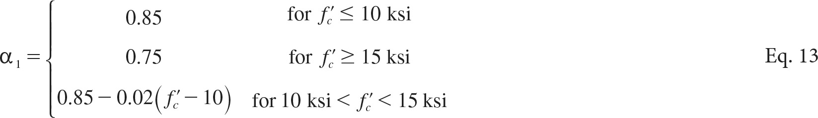
Long Description.
alpha sub 1 equals 0.85 for f prime sub c less than or equal to 10 k s i, 0.75 for f prime sub c greater than or equal to 15 k s i, and 0.85 minus 0.02 times open parenthesis f prime sub c minus 10 close parenthesis for 10 k s i less than f prime sub c less than 15 k s i.
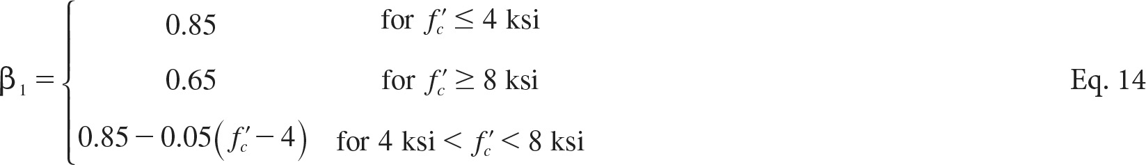
Long Description.
beta sub 1 equals 0.85 for f prime sub c less than or equal to 4 k s i, 0.65 for f prime sub c greater than or equal to 8 k s i, and 0.85 minus 0.05 times f prime sub c minus 4 for values between.
Strand rupture failure occurs when the bottom layer of SS strands reaches its specified ultimate strain value before the concrete strain in the extreme compression fiber reaches the ultimate strain of 0.003 in./in. Thus, the use of AASHTO equations for the stress block parameters (α1 and β1) is inappropriate in determining the total concrete compressive force. Stainless steel strands and CFRP strands share a similar mechanical property of limited ultimate tensile strain. NCHRP Project 12-97 (Belarbi et al., 2019) investigated the use of CFRP strands in prestressed concrete bridge beams and concluded that rupture of CFRP strands is a feasible failure mode. Therefore, NCHRP Project 12-97 proposed equations for stress block parameters, α1 and β1, for any concrete strain value in the extreme compression fiber (i.e., <0.003 in./in.), and those equations follow.

Long Description.
epsilon prime sub c equals f prime sub c over 11 plus 1.6, all multiplied by 10 to the power of negative 3.

Long Description.
beta sub 1 equals 4 minus open parenthesis epsilon sub c c over epsilon prime sub c close parenthesis over 6 minus 1 open parenthesis epsilon sub c c over epsilon prime sub c close parenthesis times open parenthesis minus f prime sub c over 50 plus 1.1 close parenthesis is greater than or equal to 0.65.

Long Description.
alpha sub 1 equals 1 over beta sub 1 times open parenthesis epsilon sub c c over epsilon prime sub c minus 1 over 3 times open parenthesis epsilon sub c c over epsilon prime sub c close parenthesis the whole squared close parenthesis times open parenthesis minus f prime sub c over 60 plus 1.0 close parenthesis.
where
εcc = strain in extreme compression fiber at failure (<0.003) (in./in.), and
ε′c = strain in concrete when the compression stress reaches f ′c as given in Eq. 15.
The total tensile force in the SS strands in the tension zone is determined from equilibrium and strain compatibility by assuming perfect bond between the SS strands and the surrounding concrete. For concrete crushing failure, an iterative approach is used to determine the nominal flexural resistance (Mn) where the neutral axis depth (c) is the only unknown parameter; once c is determined by achieving equilibrium of forces, the stress in the SS prestressing strands at each layer (fpx) can be determined. Then, the nominal flexural resistance (Mn) can be calculated.
For strand rupture failure, an iterative approach with double loops is proposed. The reason for double loops is that there are two unknowns, namely concrete strain in the extreme compression fiber (εcc) and the neutral axis depth (c). The process starts with assuming εcc (e.g., 0.001 in./in.),
then the neutral axis depth is determined through iterations to achieve equilibrium of forces. Afterward, the strain or the stress in the bottom layer of SS strands is checked, and if it reaches the ultimate strain of 0.014 in./in. or a stress of 240 ksi, then the nominal flexural resistance (Mn) can be calculated. Otherwise, the value of εcc is changed, and the process is repeated.
The steps to determine the nominal flexural resistance (Mn) are explained and discussed here in detail. A rectangular section means the neutral axis depth (c) is within the thickness of the slab (ts). Otherwise, it is considered a flanged section, in which case equations presented in the following sections are only applicable if the neutral axis lies within the top flange of the beam. In cases where the neutral axis depth is greater than the summation of the slab thickness and beam top flange thickness, it is recommended to determine the nominal flexural resistance using a nonlinear iterative sectional analysis where the stress-strain laws for the concrete are also considered.
For a rectangular section, equilibrium of forces is achieved using the following equations:
![]()
Long Description.
T equals C.

Long Description.
The summation from x equals 1 to n p of capital A sub p x times f sub p x equals alpha sub 1 times f prime sub c times beta sub 1 times c times b.
where:
T = total tensile force (kip);
C = total compressive force (kip);
np = total number of layers of prestressed tension reinforcement;
x = prestressed reinforcement layer number, starting with 1 closest to the tension face;
Apx = area of SS prestressing strand in layer x (in.2);
fpx = stress in layer x of the prestressed tension reinforcement (ksi);
c = distance from the extreme compression fiber to the neutral axis (in.); and
b = width of the compression face of the member (in.).
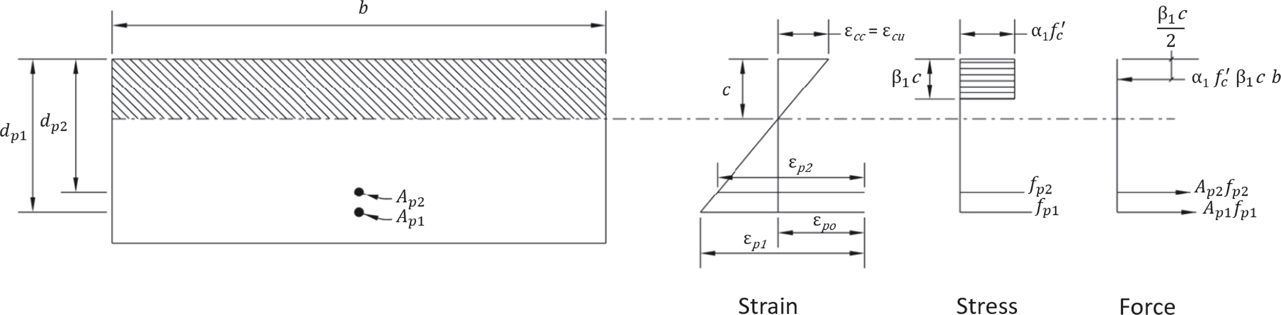
Rearranging the above equation, the neutral axis (c) can be computed from Eq. 20. For concrete crushing failure mode, α1 and β1 are known and determined using Eq. 13 and Eq. 14, respectively, where they depend on the concrete compressive strength. Figure 47 shows strain, stress and force distributions along the depth of a rectangular section failing by concrete crushing. From Figure 47, the concrete strain in the extreme compression fiber is (εcu), which is the ultimate compressive strain of concrete, while the strain in the bottom layer of strands (εp1) is less than the ultimate tensile strain of the SS strands (εpu). For strand rupture failure mode, α1 and β1 are unknown, and they depend on the concrete strain in the extreme compression
Long Description.
The illustration presents a rectangular beam section under flexure, showing strain, stress, and force distributions due to concrete crushing failure. On the left, the cross-section displays width b and two layers of prestressing strands, capital A sub p 1 at depth d sub p 1 and capital A sub p 2 at depth d sub p 2. The central diagram shows a linear strain profile from epsilon sub p 1 at the bottom to maximum strain epsilon sub c c at the top over a neutral axis depth c. The right side depicts a rectangular stress block with uniform compressive stress alpha sub 1 times f prime sub c over a depth of beta sub 1 times c, and a compressive force equal to alpha sub 1 times f prime sub c times beta sub 1 times c times b. Tensile forces from the strands are shown as capital A sub p 1 times f sub p 1 and capital A sub p 2 times f sub p 2. The stress and force diagrams align with the strain profile to represent internal force equilibrium.
fiber (εcc), which is also unknown and is determined through iterations. Once εcc is assumed, α1 and β1 can be determined using Eq. 17 and Eq. 16, respectively.

Long Description.
c equals the summation from x equals 1 to n p of capital A sub p x times f sub p x over alpha sub 1 times f prime sub c times beta sub 1 times b.
For a flanged section, equilibrium of forces is achieved by substituting the tensile and compressive forces in the flanged section in Eq. 18, and it can be written as shown in Eq. 21.

Long Description.
The summation from x equals 1 to n p of capital A sub p x times f sub p x equals alpha sub 1 times f prime sub c times beta sub 1 times c times b sub w plus alpha sub 1 times f prime sub c times t sub s times the quantity b minus b sub w.
where
ts = thickness of the slab (in.); and
bw = web width; however, used here as width of the top flange of beam (in.).
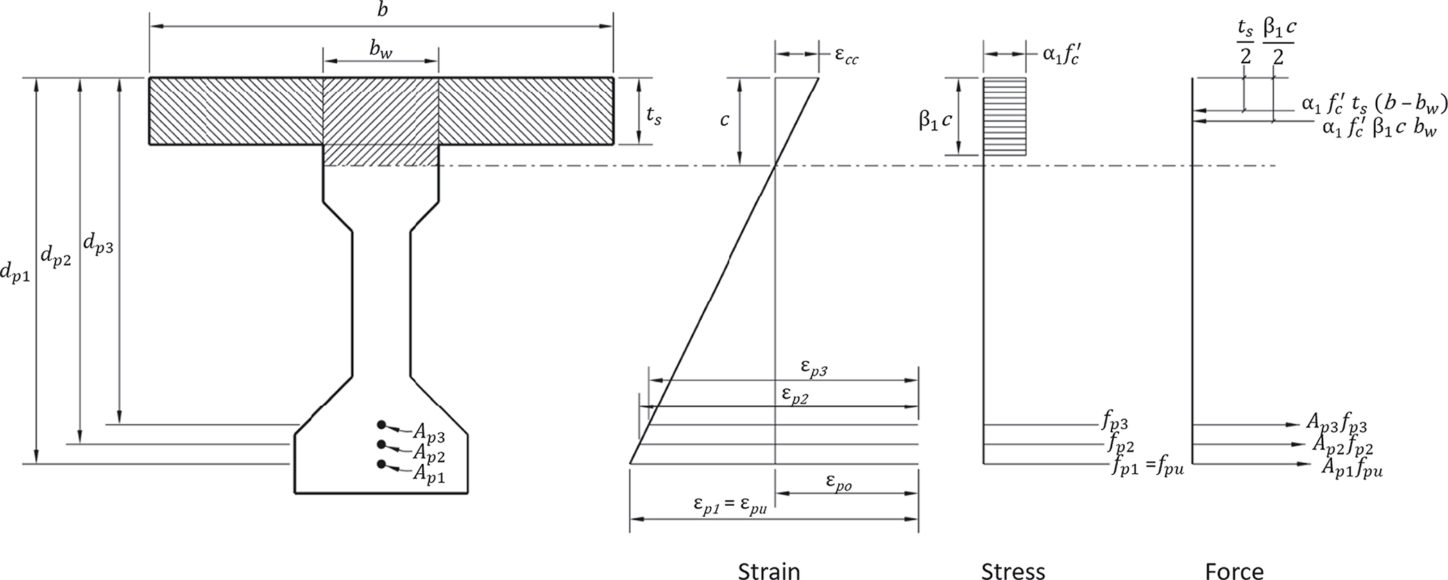
Rearranging the above equation, the neutral axis (c) can be computed from Eq. 22. For concrete crushing failure mode, α1 and β1 are known and determined using Eq. 13 and Eq. 14, respectively, where they depend on the concrete compressive strength of the slab (f′c). For strands rupture failure mode, α1 and β1 are unknown, and they depend on the concrete strain in the extreme compression fiber (εcc), which is also unknown and is determined through iterations. Once εcc is assumed, α1 and β1 can be determined using Eq. 17 and Eq. 16, respectively. Figure 48 shows strain, stress and force distributions along the depth of a flanged section (slab on top of a beam) failing by strands rupturing. From Figure 48, the strain in the bottom layer of strands is (εpu), which is the specified ultimate strain of the SS strands, while the concrete strain in the extreme compression fiber (εcc) is less than the ultimate compressive strain of concrete (εcu).

Long Description.
c equals the summation from x equals 1 to n p of capital A sub p x times f sub p x minus alpha sub 1 times f prime sub c times t sub s times the quantity b minus b sub w, all over alpha sub 1 times f prime sub c times beta sub 1 times b sub w.
Long Description.
A flange-type beam cross section with an upper slab is depicted with strain, stress, and force distributions shown across its depth. In the strain diagram, the neutral axis depth is denoted as c. The maximum concrete compressive strain epsilon sub p 2 equals epsilon sub p u. Below the neutral axis (a dash-dot line), strains in the prestressing tendons are shown as epsilon sub p 3, epsilon sub p 2, and epsilon sub p 1 equals epsilon sub p u. In the stress diagram, the stress block has a height of beta sub 1 times c and an intensity of alpha sub 1 times f prime sub c, where f prime sub c is the specified compressive strength of concrete. The prestressing tendon stress levels are labeled as f sub p 3, f sub p 2, and f sub 1 equals f sub p u. In the force diagram, the compressive force in the web is represented by alpha sub 1 times f prime sub c times beta sub 1 times c times b sub w, and the compressive force in the slab is shown as alpha sub 1 times f prime sub c times t s times open parenthesis b minus b sub w close parenthesis. The tensile forces in the tendons are A sub p 3 times f sub p 3, A sub p 2 times f sub p 2, and capital A sub p 1 times f sub p u. The layout reflects a section failing by strand rupture, with forces and stresses distributed accordingly.
For both rectangular and flanged sections, the value of c can be determined through an iterative procedure by applying compatibility equations to calculate the strain in the SS prestressing strands at each layer (εpx) for concrete crushing failure mode; or the concrete strain in the extreme compression fiber (εcc) and the strain in the SS prestressing strands at each layer (εpx) for strands rupture failure mode. For concrete crushing failure mode, the only unknown in Eq. 20 and Eq. 22 is the stress in the SS prestressing strands at each layer (fpx) where the stress in the bottom layer is less than the ultimate tensile stress of 240 ksi. For strands rupture failure mode, α1, β1 and fpx are unknown in Eq. 20 and Eq. 22, where α1 and β1 rely on the value of the concrete strain in the extreme compression zone (εcc), and fpx relies on the strain in the SS prestressing strands at each layer (εpx). The stress in the bottom layer of SS strands (fp1) is equal to the ultimate tensile stress (fpu) of 240 ksi since the failure mode is strand rupture.
The total strain in the prestressing strands at each layer (εpx) can be calculated using Eq. 23.

Long Description.
epsilon sub p x equals the sum of epsilon sub p o and epsilon sub c c times open parenthesis d sub p x over c minus 1 close parenthesis.
where εpo is the summation of εpe and εcp and they are calculated using the following equations:

Long Description.
epsilon sub p e equals f sub p e over capital E sub p.

Long Description.
epsilon sub c p equals the quantity capital P sub p t over capital A sub g plus capital P sub p t times e squared sub p g over capital I sub g, all over capital E sub c.
The stress in the SS prestressing strands at each layer (fpx) can be calculated using Eq. 26.

Long Description.
f sub p x equals capital E sub p times epsilon sub p x multiplied by the quantity capital A plus the quantity 1 minus capital A over 1 plus B times epsilon sub p x raised to the power of capital C, all raised to the power 1 over capital C.
where
εpe = strain due to effective prestress in the SS prestressing strands (in./in.);
εcp = strain in the concrete adjacent to the SS strand due to prestress for strand (in./in.);
dpx = distance from the extreme compression fiber to the centroid of SS prestressing strands in layer x, where x is replaced by the row number, with layer 1 being the layer closest to the extreme tension fiber (in.);
fpe = effective stress in SS prestressing strands after all losses (ksi);
Ep = modulus of elasticity of SS prestressing strands (ksi);
Ppt = force in SS strands immediately after transfer (kip);
Ag = gross area of beam (in.2);
epg = eccentricity of prestressing force with respect to centroid of beam at midspan (in.);
Ig = moment of inertia of the gross concrete section about the centroidal axis, neglecting the reinforcement (in.4);
Ec = modulus of elasticity of concrete in beam (ksi); and
A, B, and C = coefficients of modified Ramberg-Osgood stress-strain relationship for SS prestressing strands (A = 0.06, B = 101, and C = 6.45).
Once force equilibrium is achieved, the neutral axis depth (c) is determined, and the extreme compression fiber strain (εcc) is determined (only for strands rupture failure mode), the nominal flexural resistance (Mn) can be calculated using Eq. 27 and Eq. 28.
For a rectangular section:

Long Description.
M sub n equals the summation from x equals 1 to n p of capital A sub p x times f sub p x multiplied by the quantity d sub p x minus beta sub 1 times c over 2.
For a flanged section:

Long Description.
M sub n equals the summation from x equals 1 to n p of capital A auv p x times f p x times the quantity d auv p x minus beta sub 1 times c over 2, plus alpha sub 1 times f prime sub c times t sub s times the quantity b minus b sub w, all multiplied by the quantity beta sub 1 times c over 2 minus t sub s over 2.
In Eq. 27 and Eq. 28, for concrete crushing failure mode, use Eq. 12 and Eq. 13 for α1 and β1, respectively, and for strands rupture failure mode, use Eq. 17 and Eq. 16 for α1 and β1, respectively. More details and design examples have been provided to the AASHTO Committee on Bridges and Structures for their consideration.
5.4.2 Prestressed Beams with Unbonded Prestressed SS Strands
The design equation developed by Namaan and Alkhairi (1991) for calculating the force in unbonded prestressing tendons was utilized to formulate the proposed requirements for the SS strand. This equation incorporates a strain reduction factor (Ωu) to accommodate the absence of a bond between the tendon and the concrete. The strain reduction factor (Ωu) is defined as follows:

Long Description.
Capital omega equals 1.5 over the ratio of capital L to d sub p for single point loading.

Long Description.
Capital omega equals 3.0 over the ratio of capital L to d sub p, for two point loading, for uniform loading, or for a combination of both loadings.
The procedure used to calculate the nominal flexural resistance for bonded prestressed concrete with SS strands can also apply to unbonded prestressed concrete with SS strands. However, in this case, the strain reduction factor is utilized when calculating the total strain in the prestressing strands for each layer.
5.5 Minimum Reinforcement
According to LRFD BDS Article 5.6.3.3, concrete flexural members that are not compression-controlled should provide sufficient prestressed and non-prestressed reinforcement to develop a factored flexural resistance (Mr) greater than the lesser of 1.33Mu or Mcr, where Mu is the factored moment and Mcr is the cracking moment. A minimum reinforcement is specified to ensure that noncompression-controlled flexural members have sufficient capacity to not fail suddenly. This is achieved in concrete members with SS prestressing strands by developing new resistance factors and developing and using new compression-controlled and tension-controlled limits when determining the resistance factors.
5.6 Shear Design
The shear design of beams prestressed with SS strands is required to ensure that the beams have sufficient factored shear resistance (Vr) to resist the factored shear force (Vu). The AASHTO LRFD Bridge Design Specifications design procedure for shear can be used when SS strands are used as the main longitudinal reinforcement with the following considerations:
- The stress used for fpo in Article 5.7.3.4.2 shall be equal to 0.65fpu unless the stress immediately prior to transfer (fpbt) is less than 0.70fpu and in this case the value of fpo should be reduced accordingly.
- The effective shear depth (dv) shall be calculated using the following equation (Eq. 31); and it need not be taken to be less than the greater of 0.9de or 0.72h. Eq. 31 captures the effect of failure mode on the effective shear depth.

Long Description.
d sub v equals capital M sub n over the sum of A sub s times f sub y plus the summation from x equals 1 to n p of A sub p x times f sub p x.
where
de = effective depth from extreme compression fiber to the centroid of the tensile force in the tensile reinforcement (in.) and it shall be calculated using the equation provided in Article 5.7.2.8 in LRFD BDS 9th,
h = depth of member (in.),
As = area of nonprestressed reinforcement (in.2),
fy = yield stress in the nonprestressed reinforcement (ksi),
fpx = stress in the SS prestressing strands at layer x (ksi),
fpo = initial prestress level for SS prestressing strands (ksi), and
Apx = area of SS prestressing strand no. x (in.2).
5.7 Resistance Factors
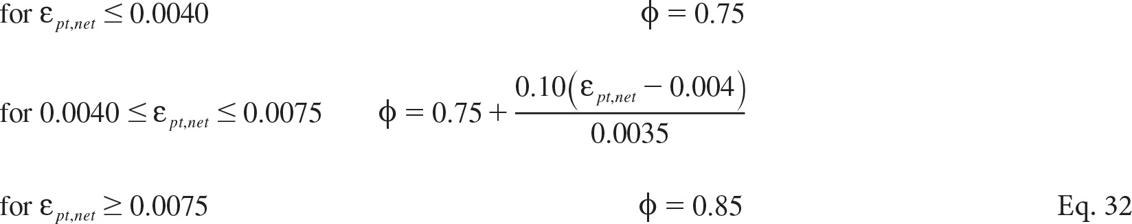
The recommended ϕ values for the flexural design of bridge elements pretensioned with SS strands or posttensioned with bonded SS tendons is proposed to be taken as follows:
Long Description.
Phi is 0.75 when epsilon p t comma net is less than or equal to 0.0040. Phi is 0.75 plus 0.10 times the quantity epsilon sub p t comma net minus 0.004 over 0.0035 when epsilon sub p t comma net is between 0.0040 and 0.0075. Phi is 0.85 when epsilon sub p t comma net is greater than or equal to 0.0075.
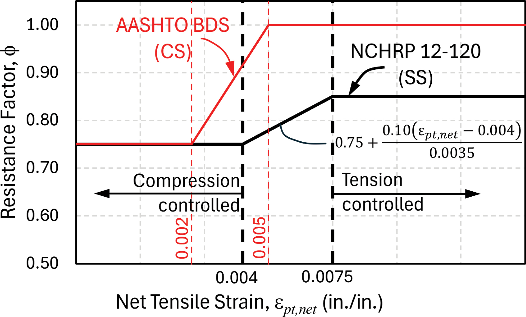
Figure 49 shows the proposed ϕ values and transition zones for the flexural design of beams pretensioned with SS strands or posttensioned with bonded SS tendons. The figure also shows the LRFD BDS ϕ – εpt,net relation for comparison between carbon steel and stainless steel requirements.
Beams posttensioned with unbonded SS tendons are susceptible to higher stress concentrations at end anchors, and therefore a constant resistance factor, ϕ, equal to 0.75 is proposed for tension- and compression-controlled sections.
Long Description.
The graph shows the relationship between resistance factor phi on the vertical axis, ranging from 0.50 to 1.00, and net tensile strain epsilon p t comma net on the horizontal axis, labeled in inches per inch. Two curves are displayed. The curve representing NCHRP 12 120, labeled as S S, starts at phi equals 0.75 for epsilon p t comma net less than or equal to 0.004, then increases linearly following the equation 0.75 plus 0.10 times the quantity epsilon p t comma net minus 0.004 over 0.0035 up to epsilon p t comma net equals 0.0075, where phi equals 0.85, and remains constant beyond that. The line for AASHTO colon BDS, labeled as CS, transitions from phi equals 0.75 to phi equals 1.00 between epsilon p t comma net values of 0.002 and 0.005. Two vertical dashed lines at epsilon p t comma net equals 0.004 and 0.0075, and 0.002 and 0.005, mark transition regions. The area to the left of 0.004 is labeled compression controlled, and the area to the right of 0.0075 is labeled tension controlled.
5.8 Proposed Language for Guide Specifications for Design and Construction
The main objective of this research project was to develop language for design and construction guide specifications in the AASHTO LRFD format for pretensioned and posttensioned concrete bridge elements prestressed with stainless steel prestressing strands. The proposed language for guide specifications provide design and construction provisions that extend the use of the LRFD BDS and the LRFD BCS for concrete bridge elements prestressed with stainless steel prestressing strands. In general, provisions in the guide specifications replace or supplement provisions in the LRFD BDS or LRFD BCS. The proposed language for guide specifications are presented as standalone documents rather than proposed revisions to the LRFD BDS and LRFD BCS because the addition of these provisions to the current design and construction specifications is expected to require some reorganization, which may also possibly involve incorporating revisions for CFRP prestressing systems.
NCHRP Project 12-120 found that concrete elements prestressed with stainless steel prestressing strands can be designed using many of the same design provisions in the LRFD BDS that apply to conventional strands conforming to ASTM A416/A416M. Where material and design properties of the SS strands differ from those for conventional CS strands, new limits or design provisions have been proposed to address the differing characteristics of stainless steel prestressing strands, which include a lower ultimate tensile strain, a lower tensile strength, and a lower modulus of elasticity, compared to the properties of conventional carbon steel prestressing strands. The reduced ultimate tensile strain of stainless steel prestressing strands was found to be the most significant difference in material properties, which resulted in a modified design approach since strand rupture is the likely failure mode. Additional attention should be given to strand tensioning operations to avoid premature spontaneous detensioning of pretensioned strands.
The findings of NCHRP Project 12-120 have been incorporated into the language for the “Proposed LRFD Guide Specifications for Design and Construction of Concrete Bridge Elements Prestressed with Stainless Steel Prestressing Strands,” which has been provided to the AASHTO Committee on Bridges and Structures for their consideration.
Designs using stainless steel prestressing strands will require a greater number of strands because of the lower tensile strength of the SS strands. The current cost of stainless steel prestressing strands is also several times greater than the cost of conventional strands. Therefore, the increased material cost combined with the greater number of strands will result in higher
costs for girders with this type of strand. However, use of stainless steel prestressing strands may be justified when the extended service life provided by these strands is considered, especially in aggressively corrosive environments.
5.9 Design Guidelines and Design Examples
To demonstrate the application of the proposed requirements for design for concrete bridge elements with stainless steel prestressing strands, design guidelines and design examples have been developed. The five design examples cover a range of span lengths and prestressed concrete bridge superstructure types and a prestressed concrete pile. Calculations in the design examples are performed in accordance with the language for “Proposed Guide Specifications for the Design of Concrete Bridge Elements Prestressed with High-Strength Stainless Steel Prestressing Strands” except for the parallel examples that use conventional CS strands, for which the calculations are performed in accordance with the LRFD BDS. The prestressed concrete bridge superstructure examples are based on examples provided in the PCI Bridge Design Manual, 4th ed. (PCI, 2023).
The five examples that are provided with the design guidelines are as follows:
- Design Examples of a Bulb-Tee (BT-72) Bridge
- Design Examples of a Box Beam (BIII-48) Bridge
- Design Examples of a Double-Tee Beam (NEXT 36D) Bridge
- Design Examples of a Florida Slab Beam (FSB) Bridge
- Design Example of a 24 in. Square Prestressed Pile
The first four design examples, which represent different prestressed concrete superstructure types, were designed for flexure considering service and strength limit states, as well as minimum reinforcement requirements. Examples 1 and 3, for the Bulb-Tee (BT-72) and Double-Tee full-depth precast beam (NEXT 36D), respectively, were also designed for shear strength using the general procedure. The designs are provided for three scenarios: SS strands with initial stress of 65% fpu; SS strands with initial stress of 70% fpu; and CS strands. For the scenarios using SS strands and CS strands with initial stress of 70% fpu, full details for all design steps and checks are provided; whereas, for the SS strands with initial stress of 65% fpu, results are included only in the summary table, which provides comparison of all final design parameters. For prestressed concrete piles, an outline provided in the design guidelines for the development of an interaction diagram for any pile prestressed with SS strands was used to prepare the design example for 24 in. square pile prestressed with 20 SS strands.


