Firepower in the Lab: Automation in the Fight Against Infectious Diseases and Bioterrorism (2001)
Chapter: New Standards and Approaches for Integrating Instruments into Laboratory Automation Systems
21
New Standards and Approaches for Integrating Instruments into Laboratory Automation Systems1
Torsten A. Staab and Gary W. Kramer
INTRODUCTION
Plug-and-play laboratory instruments are the keys to reducing integration efforts and to increasing connectivity, reuse, and scalability. This approach requires instrument manufacturers to agree on standards for controlling laboratory equipment. They also need to agree on a standardized way to describe and exchange system and device capability information. There are two approaches to interfacing standards: prescriptive and descriptive. The former approach seeks to make all devices look and behave in the same fashion to the controller. The latter concept is to employ a common way to describe the idiosyncrasies of a device and its behavior. Because it is not possible, or even desirable, to make every automation device look or behave the same, other means must be found to accommodate differences.
|
1 |
Los Alamos National Laboratory (LANL) Disclaimer of Endorsement: Reference herein to any specific commercial products, process, or service by trade name, trademark, manufacturer, or otherwise does not necessarily constitute or imply its endorsement, recommendation, or favoring by the U.S. government or the University of California. The views and opinions of authors expressed herein do not necessarily state or reflect those of the U.S. government or the University of California and shall not be used for advertising or product endorsement purposes. National Institute of Standards and Technology (NIST) Commercial Disclaimer: Certain commercial equipment, instruments, and materials are identified to describe adequately the work presented herein. Such identification does not imply recommendation or endorsement by NIST, nor does it imply that the equipment, instruments, or materials are necessarily the best available for the purpose. |
This paper describes three standardization efforts that address common instrument interfacing and integration problems. The first standardization effort discussed herein is the ASTM (American Society for Testing and Materials) E1989-98 standard, also known as LECIS (Laboratory Equipment Control Interface Specification; ASTM, 1999). LECIS defines a uniform deterministic remote control protocol for laboratory equipment. The other two standardization efforts, which are headed by the National Institute of Science and Technology (NIST), are complimentary to the ASTM LECIS standard. These efforts are known as the Device Capability Dataset (DCD; Staab and Kramer, 1998a) and the System Capability Dataset (SCD; (Piotrowski et al., 1998). The DCD defines a meta-dataset structure that captures device-specific information, such as physical dimensions, command sets, events, and resources. The SCD, on the other hand, describes the system-level capabilities. In general, these are the capabilities that are obtained by combining DCD information.
ASTM E1989-98 LECIS STANDARD
The dream of every laboratory automation engineer is to be able to integrate laboratory equipment with the plug-and-play ease of most of today's computer printers. Toward this end, the ASTM E1989-98 LECIS was developed to standardize equipment control. LECIS was developed as a generic standard that is applicable to a wide variety of equipment, from simple electronic balances to complex analytical instruments. The LECIS-defined instrument control protocol standardizes the application layer (see Figure 21.1), which is equivalent to the application layer in the OSI (Open Systems Interconnection) reference model. This standard has the advantage of being independent of low-level message-passing communications protocols. Typically, instrument message passing is accomplished by protocols such as RS-232 or TCP/IP. In the future, instruments may also be equipped with a USB (Universal Serial Bus) or an IEEE 1394 (Firewire) interface. The application layer approach has the advantage that it does not matter whether instruments and controllers are connected via a network, RS-232, or any other low-level interfacing standard.
ORIGINS OF ASTM E1989-98 LECIS
The LECIS was developed as a result of years of work by the NIST Consortium on Automated Analytical Laboratory Systems (CAALS; Kingston, 1989; Salit et al., 1994; Salit and Griesmeyer, 1997). One of the products of this industry consortium was the definition of a standard Common Command Set (Staab et al., 2000). This recommended command set was formalized into the LECIS standard by the ASTM E-49-52 Subcommittee
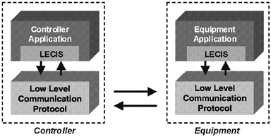
FIGURE 21.1 Protocol hierarchy.
on Computerization of Analytical Sciences Data of the ASTM E-49 Committee on Computerization of Material and Chemical Property Data (ASTM, 1999). The LECIS defines the standard equipment behavior and the messages that coordinate them in terms of the interaction model described in part by the General Equipment Interface Specification (GEIS; Griesmeyer, 1997) and in part by CAALS (Staab and Kramer, 2000). The GEIS was developed by the Intelligent Systems and Robotics Center at Sandia National Laboratory.
Control Paradigm
The LECIS instrument control concept is based on the following interactions:
-
States (discrete operational equipment states).
-
Commands (controller messages).
-
Events (equipment messages).
The standard LECIS interactions are described in the form of state diagrams, which standardize the sequence of equipment behaviors, in terms of states, and the message passing that synchronizes the execution of these behaviors, in terms of transitions between states. Figure 21.2 shows the basic elements of an interaction state diagram. ASTM E1989-98 LECIS standard-compliant instruments must support every interaction defined by the standard. The interaction models provide defined behaviors by “falling through” states that are not appropriate for individual
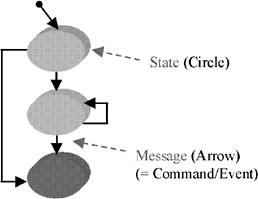
FIGURE 21.2 Interaction state diagram example.
equipment. This requirement allows the instrument controller to follow a standard control model regardless of equipment type.
Interaction Categories
The ASTM E1989-98 LECIS standard specifies required interactions only. Required interactions are interactions that all instruments must support. Equipment manufacturers can also use the LECIS interaction model to delineate equipment-specific behaviors. Equipment-specific interactions are optional interactions (see Figure 21.3).
Primary Interactions
The LECIS standard differentiates between primary and secondary interactions. Primary interactions are interactions that are started when an instrument is turned on and do not terminate until the instrument is powered down. Only one instance of a primary interaction can exist at any time. An analogy to a primary interaction is the old single-user MS-DOS operating system. When a personal computer is booted, the MS-DOS command interpreter is loaded and invoked and remains running until the PC is turned off. There can be only one command interpreter running at any time.
The ASTM E1989-98 standard defines the following two primary interactions:
-
Control flow (regulates instrument initialization, configuration, and regular operations; see Figure 21.4).
-
Local/remote control mode (manages instrument's local/remote control mode transitions).
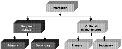
FIGURE 21.3 Interaction categories.
The primary control flow interaction, depicted in Figure 21.4, has three levels. The top level represents the regular instrument control flow. For example, after the instrument has been powered up and its communications link to the controller established, the instrument will be in a state called “powered up.” After receiving the standard INIT command, the instrument transitions from the “powered-up” state to the “initializing” state. After completion of the initialization behavior, the instrument sends a standardized event notification to the controller and transitions to the “idle” state. In the “idle” state the instrument waits for the SETUP command to start the configuration process. With the remaining standard messages, the instrument proceeds through “configuring” to “normal OPS” (OPS = Operational State), where it remains until commanded to clear itself and reenter “idle.”
States at the intermediate level of the control flow interaction define standard behaviors to pause (i.e., temporarily hold operations) and resume an instrument. If the controller commands the instrument to pause, the instrument remains in the current state in the central level while entering the “pausing” state.
The outermost level of the primary control flow interaction, shown in Figure 21.4, contains only the “Estopped” state. The “Estopped” state is used to represent an emergency shutdown. Note that a transition to “Estopped” is unidirectional, in accordance with standard safety requirements. Once in “Estopped” the local instrument operator must intervene to restart the instrument so that it reenters the “powered-up” state.
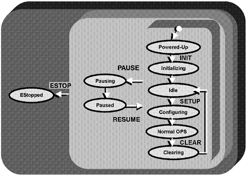
FIGURE 21.4 Control flow interaction.
Secondary Interactions
Secondary interactions are interactions that can be started and terminated at runtime. It is also possible to create multiple instances of the same interaction, allowing standard control of multitasking behavior. The ASTM E1989-98 standard defines the following required secondary interactions:
-
Processing (allows execution of instrument methods).
-
Status (retrieves status of interactions from the instrument).
-
Lock/Unlock (locks/unlocks instrument's data/material ports).
-
Item Available Notification (data/material availability notification).
-
Abort (aborts interactions).
-
Alarm (indicates instrument errors/exceptions).
-
Next Event Request (requests the next event from instrument).
ASTM E1989-98 LECIS Status and Directions
As a proof of concept, LANL successfully implemented the ASTM E1989-98 LECIS standard on an internally developed universal microtiter plate handling device.
The NCCLS (formerly the National Committee for Clinical Laboratory Standards) Area Committee on Laboratory Automation has incorporated the LECIS behavior definitions in its proposed AUTO3-P Communications with Automated Clinical Laboratory Systems, Instruments, Devices, and Information Systems standard.
LANL is currently working, with varying degrees of formality, with Bristol-Myers Squibb, CRS Robotics, Inc., ErgoTech Systems, Inc., and Pfizer to facilitate commercial adoption of the LECIS standard. Bristol-Myers Squibb intends to build standard-compliant, Active-X-based controls for its laboratory instruments. CRS Robotics, Inc., is committed to adding an ASTM E1989-98 interface to POLARA laboratory automation software. ErgoTech Systems, Inc., is developing a supported open source reference software implementation of the standard. Pfizer is currently working on a TCP/IP-based LECIS reference implementation.
The goal of this collaborative effort is also to develop CORBA (Common Request Broker Architecture) and DCOM (Distributed Component Object Model) IDL (Interface Definition Language) versions of the ASTM E1989-98 standard. The CORBA and DCOM IDL standard extensions will further simplify the development and implementation of new laboratory equipment driver software.
Many companies have expressed interest in the new ASTM E1989-98 instrument control standard. More information and progress reports on the development and implementation of the standard, as well as related projects, are available on the Web at www.lecis.org.
THE DCD
A DCD describes the idiosyncratic characteristics of laboratory equipment, such as the equipment's identity, physical dimensions, location, supported command set, generated events, input/output (I/O) ports, and other resources. The DCD concept provides a means for standardizing the interfacing of laboratory automation devices in a descriptive rather than prescriptive manner.
DCD Origins
The first steps toward the definition of a standard DCD were taken by participants of the Consortium on Automated Analytical Laboratory Sys
tems Modularity Working Group at NIST in 1994. Since then, research on the DCD topic has continued at NIST and the Fachhochschule Wiesbaden (FHW) University of Applied Sciences (Giegel, 1996; Hagemeier, 1998; Schäfer, 1996). Initial results of this joint research effort were presented at the LabAutomation'98 conference in San Diego in January 1998. The SCD, a further extension of the DCD idea that accommodates individual DCDs as well as interactions, roles, and dependencies between devices in a system, is described later in this paper. Figure 21.5 depicts the generic CAALS logical control architecture (Salit et al., 1994) showing the relationship of the DCDs and the SCD.
Structure of DCDs
A DCD, comprised of various types of information about the device, its operations, and its resources, can be organized into the following categories:
-
Identification
-
Communications
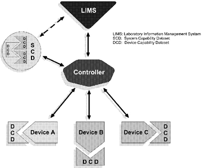
FIGURE 21.5 CAALS logic control architecture.
-
Physical characteristics
-
I/O ports
-
Commands
-
Events
-
Exceptions
-
Errors
-
Resources
-
Maintenance
In programming language terminology, such categories are the equivalent of classes or structures. Representative data and their data types contained in these DCD categories are detailed elsewhere (Staab and Kramer, 1998a, 1998b). The above DCD categories are still under development and therefore are neither final nor complete.
Static Versus Nonstatic Device Capability Data
Not all the data in DCD categories have the same temporal nature. Some information, such as the device manufacturer's name, will not change throughout the lifetime of the device and so can be considered static. Other facts, such as resource amounts and consumables, change during the operation of the device and must be accounted for dynamically. There are cases between these two extremes that range from semistatic to semidynamic data. Analytical method names could be an example of semistatic data, while a device's initial fill level might constitute semidynamic data. The exact temporal attributes assigned are less important than the concept that data in a DCD can vary in both time of inclusion and longevity. A multiauthored, multisession creation DCD process is implicit in this notion. A DCD is created along a multistep path beginning with the instrument manufacturer, who imparts much of the static data. The system integrator and methods developer supply additional static, semistatic, and semidynamic data. And the system itself, during run time, updates many of the dynamic data.
DCD Representation and Access
Currently, no consensus exists regarding the format for the storage and representation of DCDs. Whichever format is ultimately chosen for the DCD representation, the standard should be flexible, extensible, machine interpretable, and computing platform independent. To make the DCD idea work, we will either have to standardize on a single abstract metadata representation scheme or utilize compatible schemes that can be reliably interconverted electronically. (Metadata are data about data;
for example, the metadata description of a field in your address book would include the maximum length of the field, acceptable fonts to be used, etc.). Data and interface modeling languages such as the Extensible Markup Language (XML; www.w3.org/XML), the IDL (www.omg.org), or EXPRESS (ISO/TR, 1997; Schenck and Wilson, 1994; ISO 1994a, 1994b) are all current contenders for the abstract representation of a DCD.
DCD Access and Location
DCDs can be stored in anything from a simple ASCII file to a high-performance relational or object-oriented database. An entire DCD need not be constrained to a single type of storage representation—the static and dynamic DCD information could reside in different locations on different media. For example, the static parts of the DCD information might be stored in an instrument's ROM (read-only memory), on disk, or even on a networked server provided by the device manufacturer. The dynamic part could reside either in flash memory, on disc, or in random access memory.
It is crucial for the controller to have access at run time to the DCDs of all devices under its control. A controller could access a device's DCD either directly using special data commands or indirectly through normal control channel communications.
Dynamic DCD information is more likely to reside in the instrument 's local controller. The system-level device controller could retrieve such information either on demand or as a result of receiving an event message. On demand means that the controller explicitly asks the device for DCD information, and this request initiates a download of the static and dynamic DCD information from the instrument. In the event-driven model the device informs the controller each time a DCD characteristic changes by sending an event message.
DCD Status and Directions
NIST recently published its initial DCD specification (Staab and Kramer, 1998b). The Fachhochschule Wiesbaden in Germany and NIST are currently working on the first CORBA IDL-based DCD prototype implementations. Pharmaceutical companies, such as Pfizer, are working on XML-based implementations of the DCD concept. The trend toward plug-and-play instruments and component-oriented software will further foster the DCD adoption process.
THE SCD
At the system level, a controller needs to know the characteristics of the devices that it controls. However, providing the controller with access to the DCD of each instrument is not sufficient. Another construct that accounts for interdevice relationships, dependencies, and resources that are shared among devices but not part of any particular device is needed. This construct is called the SCD (Richter et al., 2000a, 2000b).
A system is more than just the sum of its parts. The system controller must have a means to account for the independent devices or SLMs (Standard Laboratory Modules; Salit et al., 1994), support devices or SSMs (System Support Modules, such as a robot or system-wide machine vision system), and system-level resources such as samples, common reagents, and storage areas (Schäfer et al., 1998). To be robust, the system controller must provide sample and resource tracking, deal with result data, and handle errors. The system controller needs a mechanism to provide its capabilities to the LIMS or the next higher level of control. Extending the DCD concept to the system level can provide all these features. As with a DCD, the SCD is comprised of building blocks, as shown in Figure 21.6. The capability dataset “puzzle” shown there is not complete—the missing piece(s) represent our current lack of understanding of what will ultimately be required to adequately represent the device or system being described in the capability dataset.
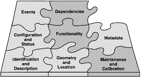
FIGURE 21.6 Components of a capability dataset.
SCD Components
Identification and Description
The identification components are used for configuration management and audit information for devices in the laboratory automation system, including the manufacturer's name, device name, device software version, and so forth.
Geometry and Location
This block holds the descriptions of physical size, shape, and location of objects and their accessible parts. Robotic paths or curves for accessing the device's ports are also parts of this block. At the system level this information is used for robot collision avoidance.
Maintenance and Calibration
Information about maintenance and calibration is used for validation and quality assurance purposes.
Configuration and Status
Both hardware and software configurations are stored in a capability dataset. The capability dataset contains configuration constraints as well as the current configuration of the objects. These data ease the configuration of a device and reduce the chances for incorrectly configuring a device. Configuration parameters are needed to set the proper functionality of a device via user methods. Status information is usually used to monitor the actions of the devices on the workbench.
Functionality
This block describes commands and their functions along with the types and ranges of any associated command data. This information enables the controller software to interact with the device because the software can both know the commands and how to use them.
Metadata
Capability datasets contain metadata for any data that can be sent from a device and that must be processed by the system. These metadata
include results data as well as status data, maintenance data, and calibration data. Metadata describe both the type and the structure of data.
Events
Device events are messages sent from the device to the controller. They are categorized into different classes such as warning, alarm, error, and data.
Dependencies
This block represents concepts such as ownership management—who can access which resource and when. Also, dependencies between different devices are stored here. For example, if the system treats a chromatograph and its autosampler as two devices, the chromatograph is dependent on the autosampler for its operation and may become useless if the autosampler fails, even though the chromatograph itself is still operable.
Static and Dynamic SCD Contents
Information enters the SCD at differing times. Some of the data are available at the time the system is designed and never change. This static part includes capabilities of the system's devices such as command sets, events, and geometry. Other SCD information is dynamic and is not known until run time—for example, sample locations, actual status of instruments, and current amounts of reagents on the workbench. Device configurations can change constantly, and even the current position of some components on the workbench can change. It is essential that the SCD provide a means for keeping track of components and their positions on the workbench. The SCD must track which device has permission to use a shared resource or port.
SCD Creation
Figure 21.7 shows a time line for the creation of an SCD. First, the device manufacturers provide the information that describes the identification, functionalities, and general behavior of the devices. This information forms the core of the DCDs for the devices. Next, the system integrator combines all of the DCDs and adds system-specific information about each device's role, position in the system, error handling, error mapping, and ownership of resources. “Superusers,” who develop analytical methods, set up the system with analytical procedures and add the information about them. Thus far, most of the information incorporated into the SCD
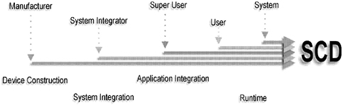
FIGURE 21.7 SCD creation timeline.
is static. Application users enter the parameters for specific runs, such as the number of samples or a specific temperature for a device. This sort of information is considered semistatic because although it is known when the run starts, the values can change as the run progresses. Finally, during run time the system supplies information to the SCD about its current state. These dynamic characteristics are primarily used for process monitoring.
SCD Representation
To construct a capability dataset that is easily reusable from system to system without significant reconstruction, device characteristics must be described as abstractly as possible. The representational scheme should be independent of the device being described, and the device/system description must be completely independent from the implementation or the platform used. Once created in this way, device information can be used as long as the device itself is used. Even when the implementation changes, the device description is not lost. To achieve the implementation independence of the capability dataset, a neutral mechanism that is capable of describing product data is needed. The information modeling language EXPRESS, contained in ISO 10313 (STEP), fulfills this requirement (ISO/TR, 1997). It is an international standard for computer-interpretable representation and exchange of product data. It is very important to note that STEP focuses not only on what the data are but also on what they mean and how they relate to one another. Originally, STEP grew out of a need to exchange product data among different computer-aided design systems. However, now it is being used in a variety of applications from metal parts fabrication to chemical plant design. The wide scope of STEP
applications means that many elements of STEP have already been invented by others. It is possible to utilize these elements, such as two-and three-dimensional geometric description schemes and tolerancing mechanisms that have already been developed and tested, without having to reinvent them. Conversely, elements specifically created for the SCD and DCD concept may be useful to others who want to utilize device characterizations and, perhaps more importantly, the descriptions of result data. This reusability of models is a big advantage to this approach.
SCD Implementation
The capability dataset approach purposefully isolates the description of the device and system from the implementation. EXPRESS, for example, provides a stable international standard for representing the SCD without worry about databases, types of databases (relational, object-oriented), or other implementation tools (ISO/TR, 1997). Furthermore, the SCD should be transparently accessible via a network in a distributed laboratory computing environment. This can be done by creating a standard interface for the SCD. NIST's current SCD approach defines the interfaces in CORBA-IDL (www.omg.org). CORBA provides the desired vendor, operating system, and programming language independence and functionality, and it is widely used in industry for the implementation of distributed systems. However, CORBA is not the only way to realize this interface. Other distributed component technologies such as Microsoft's DCOM also could be used. DCOM and CORBA are closely related system architectures and allow communication over software bridges. Since DCOM clients can easily access CORBA servers and CORBA is an independent standard, the interface definition is preferably done in CORBA-IDL.
SCD Status and Directions
The abstract EXPRESS data definitions of the SCD should eventually become part of an international standard, perhaps STEP, and should be flexible enough to allow a device manufacturer to describe all device properties and behaviors. An instrument manufacturer provides descriptions of the devices and components in STEP-like files using the SCD EXPRESS data definitions. This information is converted into transfer structures that can be understood by the capability dataset interface. These transfer structures are then stored in the underlying database in an implementation-specific format.
NIST's initial version of the SCD data definitions is complete (Staab and Kramer, 1998b). The next step, to implement the SCD concept for real devices, is currently under way at NIST in collaboration with the Wiesbaden
Computer Integrated Laboratory (WICIL) at the Fachhochschule Wiesbaden University of Applied Science (Tauber et al., 2000; Borchert et al., 2000).
CONCLUSION
In general, laboratory automation system integration is getting easier. The technologies presented here represent crucial building block technologies for the uniform, standardized, device-independent control of laboratory equipment. ASTM E1989-98 LECIS, DCD, and SCD are designed to foster the plug-and-play of laboratory instruments. Automated systems created by integrating equipment that follows these control and behavior models can be controlled more robustly and scheduled more effectively, increasing the reliability, usability, and throughput of automated systems.
Implementation projects that focus on these new technologies are currently under way at LANL, NIST, CRS Robotics, ErgoTech Systems, Pfizer, BMS, and FHW; elsewhere others are now being planned. The main purpose of these projects is to demonstrate the feasibility and real-world benefits of the ASTM LECIS, the DCD, and the SCD.
ACKNOWLEDGMENTS
The authors would like to acknowledge the work of the participants of the CAALS modularity workshops, who established the basis for standardization efforts—in particular, James R. DeVoe, Lawrence G. Falkenau, J. Michael Griesmeyer, Franklin R. Guenther, David R. Hawk, Richard S. Lysakowski, Marc L. Salit, Brian D. Seiler, William J. Sonnefeld, and John Upham. Furthermore, we are grateful for the valuable contributions of Anthony J. Day, Uwe Bernhöft, Peter J. Grandsard, Christian Piotrowski, Thorsten Richter, Thomas Tauber, Oliver Borchert, Mark F. Russo, John W. Elling, Tony J. Beugelsdijk, Robert M. Hollen, and Reinhold Schäfer.
This project is funded (in part) by NIST's Systems Integration for Manufacturing Applications (SIMA) Program. Initiated in 1994 under the federal government's high-performance computing and communications effort, SIMA addresses manufacturing systems integration problems through applications of information technologies and development of standards-based solutions. With technical activities in all of NIST's laboratories covering a broad spectrum of engineering and manufacturing domains, SIMA is making information interpretable among systems and people within and across networked enterprises.
REFERENCES
American Society for Testing and Materials. 1999. Standard Specification for Laboratory Equipment Control Interface (LECIS), ASTM E1989-98, ASTM Annual Book of ASTM Standards, 14.01, 915-939.
Borchert, O., R. Schäfer, and G. W. Kramer. 2000. Interface Definition of the System Capability Dataset Data Stream Schema. NIST Interagency Report. Washington, D.C.: U.S. Department of Commerce.
Giegel, B. 1996. Entwurf und Implementierung verteilter, objektorientierter Laborger äteschnittstellen auf der Basis des CORBA-Standards. Diploma thesis, Computer Science Department, Fachhochschule Wiesbaden Weisbaden Germany (wwwvs.informatik.fh-wiesbaden.de/publications.html).
Griesmeyer, J. M. 1997. General Equipment Interface Definition. Appendix A in Final Report: An Enabling Architecture for Information Driven Manufacturing. SAND97-2067, August 1997 (infoserve.sandia.gov/sand_doc/1997/972076.pdf).
Hagemeier, M. K. 1998. Entwurf und Implementierung einer generischen, objektorientierten Ansteuerung von Analyseautomaten unter Verwendung des CORBA-Standards Diploma thesis, Computer Science Department, Fachhochschule Wiesbaden Weisbaden Germany.
ISO. 1994a. Industrial automation systems and integration—Product data representation and exchange—STEP Part 1: Overview and fundamental principles, pp. 10303-10317.
ISO. 1994b. Industrial automation systems and integration—Product data representation and exchange—STEP Part 21: Implementation methods: Clear text encoding of the exchange structure pp.10303-12157.
ISO/TR. 1997. Industrial automation systems and integration—Product data representation and exchange—STEP Part 12: Description methods: The EXPRESS-I language reference manual, pp. 10303-10312.
Kingston, H. M. 1989. Consortium on automated analytical laboratory systems. Analytical Chemistry, 61:1381A-1384A.
Piotrowski, C., T. Richter, R. Schäfer, and G. W. Kramer. 1998. The system capability dataset for laboratory automation system integration Journal of the Association for Laboratory Automation, 3:51-55.
Richter, T., C. Piotrowski, R. Schäfer, and G. W. Kramer. 2000a. Interface Definition of Capability Datasets, Version 1.44. NIST Interagency Report. Washington, D.C.: U.S. Department of Commerce.
Richter, T., C. Piotrowski, R. Schäfer, and G. W. Kramer. 2000b. Implementation Guide to the System Capability Dataset, Version 1.15. NIST Interagency Report. Washington, D.C.: U.S. Department of Commerce.
Salit, M. L., F. R. Guenther, G. W. Kramer, and J. M. Griesmeyer. 1994. Integrating automated systems with modular architecture. Analytical Chemistry, 66:361A-367A.
Salit, M. L., and J. M. Griesmeyer. 1997. System ready behaviors for integration. Laboratory Robotics and Automation, 9:113-118.
Schäfer, R. 1996. Wiesbadener Computerintegriertes Labor (WICIL)—Entwicklung von Informatikmethoden zur Automatisierung Chemischer Analysen, Fachhochschule Wiesbaden, Germany, Ergebnisse aus Forschung und Entwicklung 27, ISBN 3-92306827-1 (www.informatik.fh-wiesbaden.de/labors/wicil.html).
Schäfer, R., T. J. Beugelsdijk, and J. W. Elling. 1998. Architectural issues for total lab automation. Presented at the International Laboratory Automation 98 Conference San Diego, Calif.
Schenck, D. A., and P. R. Wilson. 1994. Information Modeling: The EXPRESS Way. New York: Oxford University Press.
Staab, T. A., and G. W. Kramer. 1998a. The device capability dataset: A descriptive approach to laboratory automation system integration standards. Journal of the Association for Laboratory Automation, 3:45-50.
Staab, T. A., and G. W. Kramer. 1998b. Initial CAALS Device Capability Dataset, Version 1.07. NIST Interagency Report 6294 (www.lecis.org).
Staab, T. A., P. J. Grandsard, and G. W. Kramer. 2000. CAALS Common Command Set. NIST Interagency Report. Washington, D.C.: U.S. Department of Commerce.
Staab, T. A., and G. W. Kramer. 2000. CAALS High-Level Communication Protocol. NIST Interagency Report. Washington, D.C.: U.S. Department of Commerce.
Tauber, T., R. Schäfer, and G. W. Kramer. 2000. Device Communication Principles for Automation Systems Using a System Capability Dataset. NIST Interagency Report. Washington, D.C.: U.S. Department of Commerce.