Pile Design for Downdrag: Examples and Supporting Materials (2024)
Chapter: Appendix J: Design Example 8 - Embankment Over Clay Over Rock Using PileAXL
APPENDIX J
Design Example 8 — Embankment Over Clay Over Rock Using PileAXL
Table J1. Budge and Dasenbrock (2016) MN 74551 data.
| Pile Material | Steel |
| Pile Shape | H-Pile (HP12x53) |
| Pile Width [in] | 12 |
| Pile Height [in] | 11.8 |
| Pile Web and Flange Thickness [in] | 0.435 |
| Pile Area [in2] | 15.19 |
| Pile Embedded Length [ft] | 52 |
| Pile Modulus [ksi] | 29000 |
| Top Load on Pile [lb] | 0 |
| Number of Pile Increments | 52 |
| Soil Compression Ratio (Rc) | 0.033 |
| Soil Recompression Ratio (Rr) | 0.005 |
| Depositional Environment | Normally Consolidated |
| Ground Water Table Depth [ft] | 0 |
| Fill Height [ft] | 29 |
| Fill Unit Weight [pcf] | 120 |
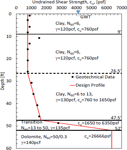
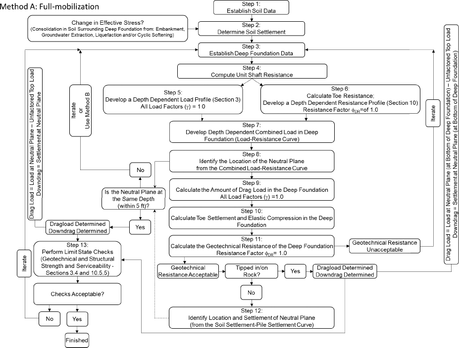
The data for the design example that is contained herein were obtained from Budge and Dasenbrock (2016). Specific information related to the piles for the Minnesota 74551 bridge is included in Table J1. The MN 74551 bridge was constructed as a grade separation/overpass for an existing railway line. The soils at the site were normally consolidated and the settlement resulting from the overpass fill was of concern for drag load and downdrag development on the abutment piles. The piles that were driven at the site were HP12x53 H-piles (width=12in, web thickness=0.435in, pile area=15.19in2). The piles were driven to an embedded length of 52 feet with an additional 30 feet of stickup to protrude through the embankment fill. At 52 feet, the piles were expected to encounter a rock bearing layer (Figure J1). Downdrag and drag load prevention methods in the form of corrugated metal pile sleeves within the fill were used. Several of the piles were also instrumented to investigate the amount of reduction attributed to the prevention methods. Method A (flow chart provided on next page) as proposed by the NCHRP12-116A team was employed.
Step 1: Establish oil data
The undrained shear strength was correlated with the N60 corrected blow count values using the atmospheric pressure, pa=2116psf (Equation 1). The soil layering was developed based on the observed SPT blow count values and the obtained moisture content profile. An undrained shear strength value is presented for the rock layer below 52 feet instead of an unconfined compression strength because the Ensoft TZPILE(Ensoft 2021) program does contain pre-programmed t-z and q-w curves for rock.
| Eqn. 1 (Kulhawy and Mayne, 1990) |
Step 2: Determine soil settlement
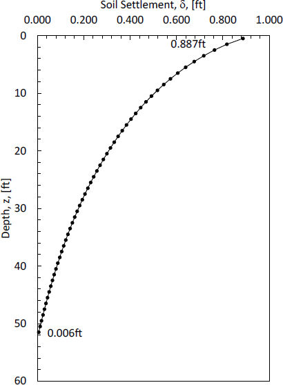
Similar to Design Example 1, the amount of expected soil settlement is determined using consolidation theory. The soil settlement profile shown in Figure J2 was created by discretizing the soil into sublayers (52, 1ft thick layers) and then calculating the amount of settlement within each sublayer resulting from a non-symmetric 29ft thick, 28.7ft crest, 59ft base embankment fill (Figure J3), with a unit weight of 120pcf, being placed on top of the two-layer clay soil profile overlaying the weathered rock layer and parent rock. The irregular shape of the embankment was attributed to the existing railway right-of-way on the left side of the embankment shown in Figure J3. Equations similar to those used in Design Example 1 were used to determine the soil settlement. Two differences were observed between the soil settlement calculations contained herein and the soil settlement calculations in Design Example 1. These include: 1) the embankment is not symmetric about the center therefore influence factors for both the left and the right side of the embankment must be determined as a function of depth, and 2) the compression and recompression ratios were used for the settlement calculations instead of soil modulus values. The equations used to find the influence factor (I) are presented in Equations 2 through 4. The variables required in Equations 2 through 4 are presented in Figure J3. The amount of settlement was determined for each sublayer using Equations 5 and 6. The z, σzo′, α, I, ∆σ, σzf’, and δ are presented in Table J2.
| Eqn. 2 |
| Eqn. 3 |
| Eqn. 4 |
| Eqn. 5 |
| Eqn. 6 |
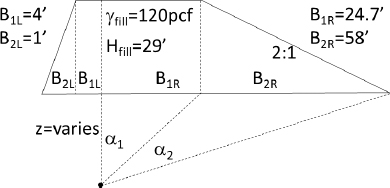
Table J2. Parameters used to find soil settlement.
| Layer Depth | z | σzo′ | α1,L | α1,L | IL | α1,R | α1,R | IR | Σ(I) | ∆σ | σ′zf | δinc | Σδ | ||
| 0 | - | 1 | 0.5 | 28.8 | 0.025 | 1.446 | 0.500 | 0.014 | 1.551 | 0.500 | 1.000 | 3479 | 3508 | 0.069 | 0.069 |
| 1 | - | 2 | 1.5 | 86.4 | 0.067 | 1.212 | 0.493 | 0.043 | 1.510 | 0.500 | 0.993 | 3455 | 3542 | 0.054 | 0.123 |
| 2 | - | 3 | 2.5 | 144 | 0.095 | 1.012 | 0.473 | 0.071 | 1.470 | 0.500 | 0.973 | 3387 | 3531 | 0.046 | 0.169 |
| 3 | - | 4 | 3.5 | 201.6 | 0.108 | 0.852 | 0.443 | 0.099 | 1.430 | 0.500 | 0.943 | 3282 | 3484 | 0.041 | 0.210 |
| 4 | - | 5 | 4.5 | 259.2 | 0.111 | 0.727 | 0.408 | 0.126 | 1.390 | 0.500 | 0.908 | 3161 | 3420 | 0.037 | 0.247 |
| 5 | - | 6 | 5.5 | 316.8 | 0.109 | 0.629 | 0.374 | 0.153 | 1.351 | 0.500 | 0.873 | 3039 | 3356 | 0.034 | 0.281 |
| 6 | - | 7 | 6.5 | 374.4 | 0.104 | 0.552 | 0.341 | 0.179 | 1.313 | 0.499 | 0.840 | 2925 | 3299 | 0.031 | 0.313 |
| 7 | - | 8 | 7.5 | 432 | 0.098 | 0.490 | 0.312 | 0.205 | 1.275 | 0.499 | 0.811 | 2822 | 3254 | 0.029 | 0.342 |
| 8 | - | 9 | 8.5 | 489.6 | 0.092 | 0.440 | 0.286 | 0.230 | 1.239 | 0.498 | 0.785 | 2731 | 3220 | 0.027 | 0.369 |
| 9 | - | 10 | 9.5 | 547.2 | 0.086 | 0.399 | 0.264 | 0.253 | 1.203 | 0.498 | 0.762 | 2650 | 3197 | 0.025 | 0.395 |
| 10 | - | 11 | 10.5 | 604.8 | 0.080 | 0.364 | 0.244 | 0.276 | 1.168 | 0.497 | 0.741 | 2579 | 3184 | 0.024 | 0.419 |
| 11 | - | 12 | 11.5 | 662.4 | 0.075 | 0.335 | 0.227 | 0.298 | 1.134 | 0.496 | 0.723 | 2516 | 3178 | 0.023 | 0.441 |
| 12 | - | 13 | 12.5 | 720 | 0.071 | 0.310 | 0.211 | 0.319 | 1.101 | 0.495 | 0.707 | 2459 | 3179 | 0.021 | 0.463 |
| 13 | - | 14 | 13.5 | 777.6 | 0.067 | 0.288 | 0.198 | 0.339 | 1.070 | 0.494 | 0.692 | 2409 | 3186 | 0.020 | 0.483 |
| 14 | - | 15 | 14.5 | 835.2 | 0.063 | 0.269 | 0.186 | 0.358 | 1.039 | 0.493 | 0.679 | 2363 | 3198 | 0.019 | 0.502 |
| 15 | - | 16 | 15.5 | 892.8 | 0.059 | 0.253 | 0.175 | 0.376 | 1.009 | 0.492 | 0.667 | 2321 | 3214 | 0.018 | 0.521 |
| 16 | - | 17 | 16.5 | 950.4 | 0.056 | 0.238 | 0.165 | 0.393 | 0.981 | 0.490 | 0.656 | 2282 | 3233 | 0.018 | 0.538 |
| 17 | - | 18 | 17.5 | 1008 | 0.054 | 0.225 | 0.157 | 0.409 | 0.953 | 0.489 | 0.646 | 2247 | 3255 | 0.017 | 0.555 |
| 18 | - | 19 | 18.5 | 1065.6 | 0.051 | 0.213 | 0.149 | 0.424 | 0.927 | 0.487 | 0.636 | 2214 | 3280 | 0.016 | 0.572 |
| 19 | - | 20 | 19.5 | 1123.2 | 0.049 | 0.202 | 0.142 | 0.438 | 0.902 | 0.485 | 0.627 | 2183 | 3306 | 0.016 | 0.587 |
| 20 | - | 21 | 20.5 | 1180.8 | 0.047 | 0.193 | 0.135 | 0.451 | 0.877 | 0.484 | 0.619 | 2154 | 3335 | 0.015 | 0.602 |
| 21 | - | 22 | 21.5 | 1238.4 | 0.045 | 0.184 | 0.129 | 0.463 | 0.854 | 0.482 | 0.611 | 2126 | 3365 | 0.014 | 0.617 |
| 22 | - | 23 | 22.5 | 1296 | 0.043 | 0.176 | 0.124 | 0.474 | 0.831 | 0.480 | 0.604 | 2100 | 3396 | 0.014 | 0.630 |
| 23 | - | 24 | 23.5 | 1353.6 | 0.041 | 0.169 | 0.119 | 0.484 | 0.809 | 0.477 | 0.596 | 2075 | 3429 | 0.013 | 0.644 |
| 24 | - | 25 | 24.5 | 1411.2 | 0.039 | 0.162 | 0.114 | 0.494 | 0.788 | 0.475 | 0.589 | 2051 | 3463 | 0.013 | 0.657 |
| 25 | - | 26 | 25.5 | 1468.8 | 0.038 | 0.156 | 0.110 | 0.503 | 0.768 | 0.473 | 0.583 | 2028 | 3497 | 0.013 | 0.669 |
| 26 | - | 27 | 26.5 | 1526.4 | 0.037 | 0.150 | 0.106 | 0.511 | 0.749 | 0.470 | 0.576 | 2006 | 3532 | 0.012 | 0.681 |
| 27 | - | 28 | 27.5 | 1594 | 0.035 | 0.144 | 0.102 | 0.519 | 0.731 | 0.468 | 0.570 | 1985 | 3579 | 0.012 | 0.693 |
| 28 | - | 29 | 28.5 | 1661.6 | 0.034 | 0.139 | 0.099 | 0.526 | 0.713 | 0.465 | 0.564 | 1964 | 3625 | 0.011 | 0.704 |
| 29 | - | 30 | 29.5 | 1729.2 | 0.033 | 0.135 | 0.096 | 0.532 | 0.696 | 0.463 | 0.558 | 1943 | 3673 | 0.011 | 0.715 |
| 30 | - | 31 | 30.5 | 1796.8 | 0.032 | 0.130 | 0.093 | 0.538 | 0.680 | 0.460 | 0.553 | 1924 | 3720 | 0.011 | 0.726 |
| 31 | - | 32 | 31.5 | 1864.4 | 0.031 | 0.126 | 0.090 | 0.543 | 0.664 | 0.458 | 0.547 | 1904 | 3769 | 0.010 | 0.736 |
| 32 | - | 33 | 32.5 | 1932 | 0.030 | 0.122 | 0.087 | 0.547 | 0.649 | 0.455 | 0.542 | 1885 | 3817 | 0.010 | 0.746 |
| 33 | - | 34 | 33.5 | 1999.6 | 0.029 | 0.119 | 0.084 | 0.551 | 0.634 | 0.452 | 0.537 | 1867 | 3867 | 0.010 | 0.755 |
| 34 | - | 35 | 34.5 | 2067.2 | 0.028 | 0.115 | 0.082 | 0.555 | 0.620 | 0.449 | 0.531 | 1849 | 3916 | 0.009 | 0.764 |
| 35 | - | 36 | 35.5 | 2134.8 | 0.028 | 0.112 | 0.080 | 0.558 | 0.607 | 0.446 | 0.526 | 1831 | 3966 | 0.009 | 0.773 |
| 36 | - | 37 | 36.5 | 2202.4 | 0.027 | 0.109 | 0.078 | 0.561 | 0.594 | 0.444 | 0.521 | 1814 | 4016 | 0.009 | 0.782 |
| 37 | - | 38 | 37.5 | 2270 | 0.026 | 0.106 | 0.076 | 0.563 | 0.582 | 0.441 | 0.516 | 1797 | 4067 | 0.008 | 0.790 |
| 38 | - | 39 | 38.5 | 2337.6 | 0.026 | 0.104 | 0.074 | 0.565 | 0.569 | 0.438 | 0.511 | 1780 | 4117 | 0.008 | 0.799 |
| 39 | - | 40 | 39.5 | 2405.2 | 0.025 | 0.101 | 0.072 | 0.567 | 0.558 | 0.435 | 0.507 | 1763 | 4169 | 0.008 | 0.807 |
| 40 | - | 41 | 40.5 | 2472.8 | 0.024 | 0.098 | 0.070 | 0.568 | 0.547 | 0.432 | 0.502 | 1747 | 4220 | 0.008 | 0.814 |
| 41 | - | 42 | 41.5 | 2540.4 | 0.024 | 0.096 | 0.068 | 0.569 | 0.536 | 0.429 | 0.497 | 1731 | 4271 | 0.007 | 0.822 |
| 42 | - | 43 | 42.5 | 2608 | 0.023 | 0.094 | 0.067 | 0.570 | 0.526 | 0.426 | 0.493 | 1715 | 4323 | 0.007 | 0.829 |
| 43 | - | 44 | 43.5 | 2675.6 | 0.023 | 0.092 | 0.065 | 0.571 | 0.516 | 0.423 | 0.488 | 1700 | 4375 | 0.007 | 0.836 |
| 44 | - | 45 | 44.5 | 2743.2 | 0.022 | 0.090 | 0.064 | 0.571 | 0.506 | 0.420 | 0.484 | 1684 | 4427 | 0.007 | 0.843 |
| 45 | - | 46 | 45.5 | 2810.8 | 0.022 | 0.088 | 0.063 | 0.571 | 0.496 | 0.417 | 0.480 | 1669 | 4480 | 0.007 | 0.850 |
| 46 | - | 47 | 46.5 | 2878.4 | 0.021 | 0.086 | 0.061 | 0.571 | 0.487 | 0.414 | 0.475 | 1654 | 4533 | 0.007 | 0.856 |
| 47 | - | 48 | 47.5 | 2946 | 0.021 | 0.084 | 0.060 | 0.570 | 0.479 | 0.411 | 0.471 | 1639 | 4585 | 0.006 | 0.863 |
| 48 | - | 49 | 48.5 | 3018.6 | 0.020 | 0.082 | 0.059 | 0.570 | 0.470 | 0.408 | 0.467 | 1625 | 4643 | 0.006 | 0.869 |
| 49 | - | 50 | 49.5 | 3091.2 | 0.020 | 0.081 | 0.058 | 0.569 | 0.462 | 0.405 | 0.463 | 1610 | 4702 | 0.006 | 0.875 |
| 50 | - | 51 | 50.5 | 3163.8 | 0.020 | 0.079 | 0.056 | 0.568 | 0.454 | 0.402 | 0.459 | 1596 | 4760 | 0.006 | 0.881 |
| 51 | - | 52 | 51.5 | 3236.4 | 0.019 | 0.078 | 0.055 | 0.567 | 0.446 | 0.399 | 0.455 | 1582 | 4819 | 0.006 | 0.887 |
| z=layer midpoint depth [ft], σ′z=vertical effective stress [psf], α1 and α2=angles [radians] from Figure J3, I=influence factor, ∆σ=change in stress [psf], δinc=settlement of sublayer [ft], Σδ (from bottom to top) = soil settlement profile (Figure J2). L=left, R=right, o=initial, f=final. | |||||||||||||||
Step 3: Establish pile data
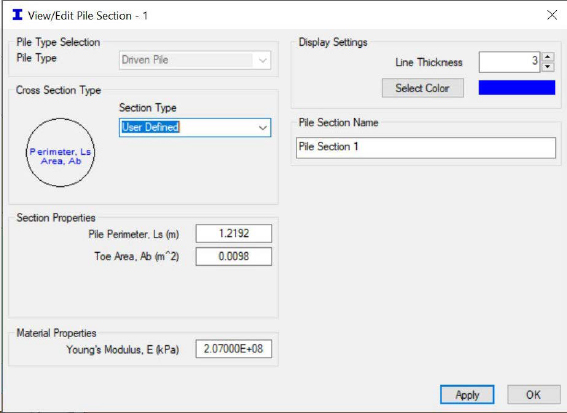
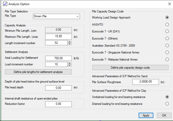
The pile data was loaded into the Innovative Geotechnics (2023) PileAXL program (Version 2.5). As mentioned in the description of the previous design examples that used the Innovative Geotechnics programs, the programs only accept metric units. Therefore, many of the parameters were converted between imperial units and metric units. The input data, within the PileAXL program, are shown in Figures J4 through J12. The pile section properties and analysis options are shown in Figures J4 and J5, respectively. As recommended by Innovative Geotechnics, the User Defined option was selected to prevent the use of the gross area of the pile.
Step 4: Compute unit side resistance
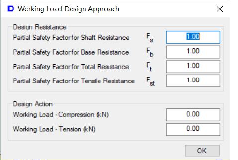
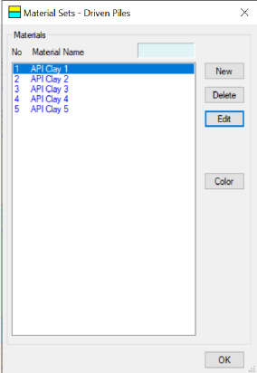
The working load design approach that was utilized is presented in Figure J6. As with all of the other design examples, all of the used loads were unfactored loads and all of the determined resistances were unfactored resistances. Therefore, the factors of safety values in Figure J6 were set to unity. The different soil layer materials were created using the Material Sets, as shown in Figure J7. Each of the materials was created and then modified by selecting the Edit button to enable input of the various soil parameters (material type, material name, total unit weight, undrained shear strength, and undrained shear strength increase) as shown in Figure J8. Although the bearing layer was rock and there is a rock option in the PileAXL software, the PileAXL software required unconfined compressive strength that was not available. Therefore, clay parameters were used for the rock layer; the undrained shear strength (1276kPa) was selected from back-analyzing nominal unit tip resistance values for dolomite (240ksf) that were recommended by the Illinois Department of Transportation (2009). After assigning material properties to the respective layers (Figure J9), all of the maximum unit end bearing and maximum unit side resistance values remained at the default values (Figure J10). All of the required information was available within the program at the end of the definition of soil layers stage (Figure J11). The program was then executed to obtain the desired results that are presented in Figure J12 and Table J3. The discretized side resistance is represented as ∆Q in Table J3.
Steps 5 and 6: Develop the depth-dependent load profile anddepth-dependent resistance profile
The depth-dependent load profile and resistance profile data are presented in Table J3. Specifically, the load data are represented by the variable Q in Table J3 and the resistance data are represented as R in Table J3.
Steps 7, 8, and 9: Develop the depth-dependent combined load-resistance curve, identify the location of the neutral plane, and calculate the drag load in the pile
The depth-dependent combined load-resistance curve is plotted in Figure J13. The combined curve was developed by plotting the minimum value of load and resistance at each depth, as a function of depth (Figure J13). The location of the neutral plane was identified as the depth at which the maximum value of the load-resistance value occurred. From the load-resistance curve, the neutral plane was identified
to occur at a depth of 43ft below the existing ground surface. The drag load was determined to be 44.0tons.
Steps 10 and 11: Calculate the toe movement and elastic compression in the pile; determine geotechnical resistance of the pile
As shown in Figure J14, a calculated pile head movement of 0.441in and a geotechnical resistance of 88.8kN were obtained. For completeness, the data contained in Figure J14 are also tabulated in Table J4. According to the NCHRP12-116A Method A flowchart, the soil settlement-pile settlement data (Step 12) are not required because the pile is tipped into rock. Although toe movement and elastic compression were obtained, these values are not presented because Step 12 was not needed.
Step 13: Perform limit state checks
Limit state checks were performed to determine if the pile size was suitable for the design loads. For the structural strength limit state, the determined drag load (44tons) was multiplied by the drag load factor (γDR=1.1) to obtain a factored drag load of 48tons. The unfactored and factored top load deadload were 0tons. The combined total factored load was 48tons. The yield stress for the steel pile was assumed to be 45ksi resulting in a factored structural stress of 40.5ksi (0.9*45ksi) and a factored structural strength of 308tons when the stress was multiplied by the cross-sectional area of the pile wall (15.19in2). If Grade 3 A-252 HP12x53 H-piles were used then the piles are adequately sized; the factored structural strength was determined to be greater than the combined total factored load.
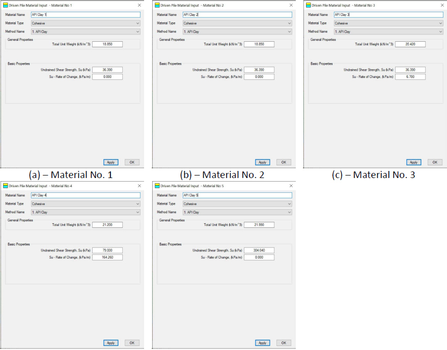

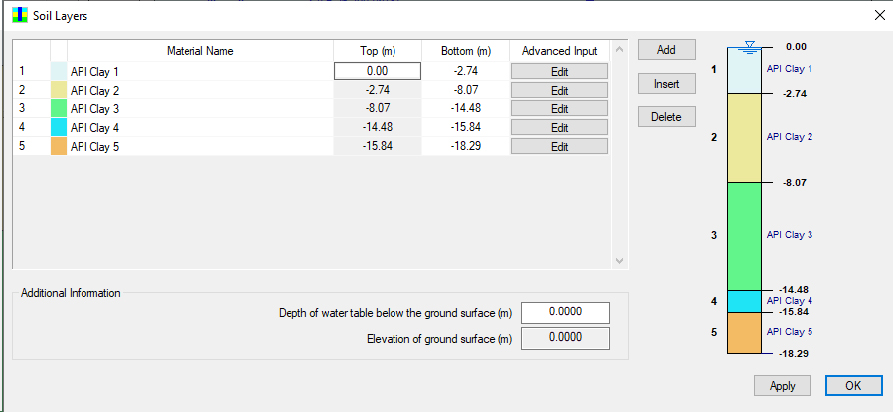
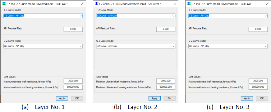
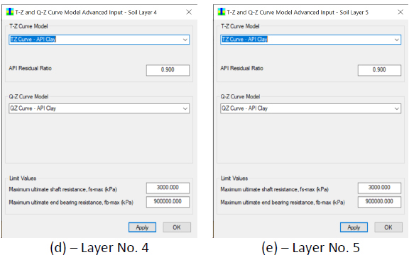
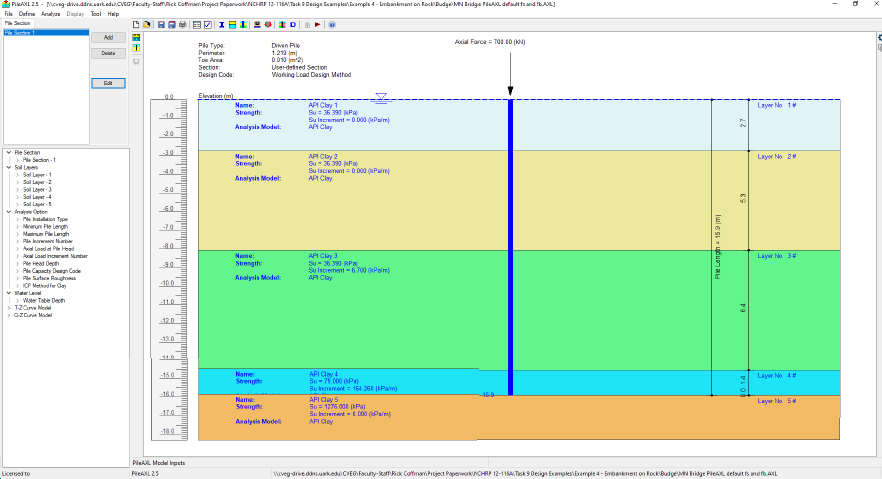
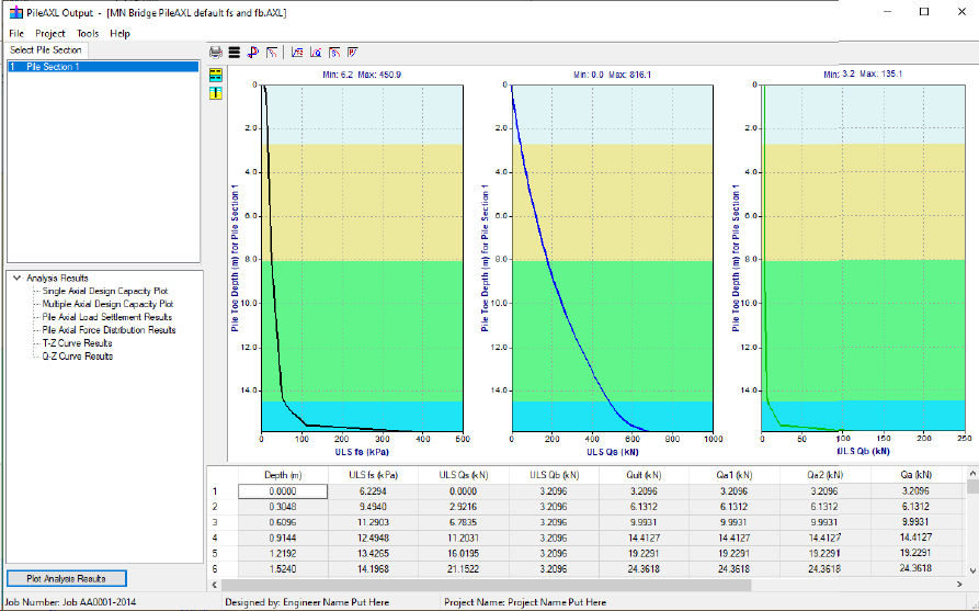
Table J3. PileAXL output for the MN 74551 bridge abutment piles.
| Depth | ULS fs | ULS Qs | ULS Qb | ∆Q | Q | R | min(Q,R) | δpile | Comments: ULS fs = Ultimate unit side resistance (PileAXL output), ULS Qs = Ultimate total side resistance (PileAXL output), ULS Qb = Ultimate bearing resistance (PileAXL output), ∆Q = discretized side resistance (Excel calculation), Q = cumulative load in the pile (Excel calculation), R= resistance from soil surrounding pile; resistance values are calculated at the top of each sublayer (Excel calculation), min(Q,R) = minimum of Q and R for each depth (Excel calculation), δpile=Settlement of pile obtained by determining the pile head movement from the PileAXL load-settlement curve (Figure J13) and the elastic compression. |
| [ft] | [tsf] | [tons] | [tons] | [tons] | [tons] | [tons] | [tons] | [in] | |
| 0.000 | 0.700 | 0.000 | 0.361 | 0.328 | 0.000 | 89.099 | 0.000 | 0.441 | |
| 1.000 | 1.067 | 0.328 | 0.361 | 0.434 | 0.328 | 88.770 | 0.328 | 0.441 | |
| 2.000 | 1.269 | 0.762 | 0.361 | 0.497 | 0.762 | 88.336 | 0.762 | 0.441 | |
| 3.000 | 1.404 | 1.259 | 0.361 | 0.541 | 1.259 | 87.840 | 1.259 | 0.441 | |
| 4.000 | 1.509 | 1.801 | 0.361 | 0.577 | 1.801 | 87.298 | 1.801 | 0.441 | |
| 5.000 | 1.596 | 2.378 | 0.361 | 0.607 | 2.378 | 86.721 | 2.378 | 0.441 | |
| 6.000 | 1.670 | 2.984 | 0.361 | 0.633 | 2.984 | 86.114 | 2.984 | 0.441 | |
| 7.000 | 1.736 | 3.617 | 0.361 | 0.656 | 3.617 | 85.481 | 3.617 | 0.441 | |
| 8.000 | 1.795 | 4.273 | 0.361 | 0.677 | 4.273 | 84.825 | 4.273 | 0.441 | |
| 9.000 | 1.848 | 4.950 | 0.361 | 0.696 | 4.950 | 84.149 | 4.950 | 0.441 | |
| 10.000 | 1.898 | 5.646 | 0.361 | 0.714 | 5.646 | 83.452 | 5.646 | 0.441 | |
| 11.000 | 1.943 | 6.360 | 0.361 | 0.730 | 6.360 | 82.739 | 6.360 | 0.441 | |
| 12.000 | 1.986 | 7.090 | 0.361 | 0.746 | 7.090 | 82.009 | 7.090 | 0.441 | |
| 13.000 | 2.026 | 7.836 | 0.361 | 0.764 | 7.836 | 81.263 | 7.836 | 0.441 | |
| 14.000 | 2.083 | 8.600 | 0.361 | 0.788 | 8.600 | 80.499 | 8.600 | 0.441 | |
| 15.000 | 2.157 | 9.387 | 0.361 | 0.815 | 9.387 | 79.711 | 9.387 | 0.441 | |
| 16.000 | 2.227 | 10.202 | 0.361 | 0.840 | 10.202 | 78.897 | 10.202 | 0.441 | |
| 17.000 | 2.296 | 11.042 | 0.361 | 0.866 | 11.042 | 78.056 | 11.042 | 0.441 | |
| 18.000 | 2.362 | 11.908 | 0.361 | 0.890 | 11.908 | 77.191 | 11.908 | 0.441 | |
| 19.000 | 2.427 | 12.798 | 0.361 | 0.914 | 12.798 | 76.301 | 12.798 | 0.441 | |
| 20.001 | 2.490 | 13.712 | 0.361 | 0.937 | 13.712 | 75.387 | 13.712 | 0.441 | |
| 21.001 | 2.552 | 14.649 | 0.361 | 0.959 | 14.649 | 74.450 | 14.649 | 0.441 | |
| 22.001 | 2.612 | 15.608 | 0.361 | 0.982 | 15.608 | 73.491 | 15.608 | 0.441 | |
| 23.001 | 2.671 | 16.590 | 0.361 | 1.003 | 16.590 | 72.509 | 16.590 | 0.440 | |
| 24.001 | 2.728 | 17.593 | 0.361 | 1.024 | 17.593 | 71.506 | 17.593 | 0.440 | |
| 25.001 | 2.784 | 18.617 | 0.361 | 1.045 | 18.617 | 70.482 | 18.617 | 0.440 | |
| 26.001 | 2.839 | 19.662 | 0.361 | 1.074 | 19.662 | 69.437 | 19.662 | 0.440 | |
| 27.001 | 2.941 | 20.736 | 0.371 | 1.120 | 20.736 | 68.363 | 20.736 | 0.440 | |
| 28.001 | 3.085 | 21.855 | 0.392 | 1.173 | 21.855 | 67.244 | 21.855 | 0.440 | |
| 29.001 | 3.229 | 23.028 | 0.412 | 1.227 | 23.028 | 66.070 | 23.028 | 0.440 | |
| 30.001 | 3.373 | 24.255 | 0.432 | 1.280 | 24.255 | 64.844 | 24.255 | 0.440 | |
| 31.001 | 3.516 | 25.535 | 0.452 | 1.333 | 25.535 | 63.564 | 25.535 | 0.439 | |
| 32.001 | 3.660 | 26.869 | 0.473 | 1.387 | 26.869 | 62.230 | 26.869 | 0.439 | |
| 33.001 | 3.804 | 28.255 | 0.493 | 1.440 | 28.255 | 60.843 | 28.255 | 0.439 | |
| 34.001 | 3.947 | 29.696 | 0.513 | 1.494 | 29.696 | 59.403 | 29.696 | 0.439 | |
| 35.001 | 4.091 | 31.189 | 0.533 | 1.547 | 31.189 | 57.910 | 31.189 | 0.439 | |
| 36.001 | 4.235 | 32.736 | 0.554 | 1.600 | 32.736 | 56.362 | 32.736 | 0.439 | |
| 37.001 | 4.378 | 34.337 | 0.574 | 1.654 | 34.337 | 54.762 | 34.337 | 0.438 | |
| 38.001 | 4.522 | 35.990 | 0.594 | 1.707 | 35.990 | 53.108 | 35.990 | 0.438 | |
| 39.001 | 4.665 | 37.698 | 0.614 | 1.760 | 37.698 | 51.401 | 37.698 | 0.438 | |
| 40.001 | 4.809 | 39.458 | 0.635 | 1.814 | 39.458 | 49.641 | 39.458 | 0.438 | |
| 41.001 | 4.952 | 41.272 | 0.655 | 1.867 | 41.272 | 47.827 | 41.272 | 0.438 | |
| 42.001 | 5.096 | 43.139 | 0.675 | 1.920 | 43.139 | 45.960 | 43.139 | 0.437 | |
| 43.001 | 5.239 | 45.059 | 0.695 | 1.974 | 45.059 | 44.040 | 44.040 | 0.437 | |
| 44.001 | 5.383 | 47.033 | 0.716 | 2.027 | 47.033 | 42.066 | 42.066 | 0.437 | |
| 45.001 | 5.526 | 49.060 | 0.736 | 2.080 | 49.060 | 40.039 | 40.039 | 0.437 | |
| 46.001 | 5.669 | 51.140 | 0.756 | 2.134 | 51.140 | 37.959 | 37.959 | 0.436 | |
| 47.001 | 5.813 | 53.273 | 0.776 | 2.338 | 53.273 | 35.825 | 35.825 | 0.436 | |
| 48.001 | 6.772 | 55.612 | 1.029 | 2.837 | 55.612 | 33.487 | 33.487 | 0.436 | |
| 49.001 | 8.494 | 58.448 | 1.525 | 3.539 | 58.448 | 30.651 | 30.651 | 0.436 | |
| 50.001 | 10.555 | 61.988 | 2.021 | 4.287 | 61.988 | 27.111 | 27.111 | 0.436 | |
| 51.001 | 12.516 | 66.274 | 2.518 | 10.174 | 66.274 | 22.824 | 22.824 | 0.435 |
| 52.001 | 42.239 | 76.448 | 12.650 | 76.448 | 12.650 | 12.650 | 0.435 |
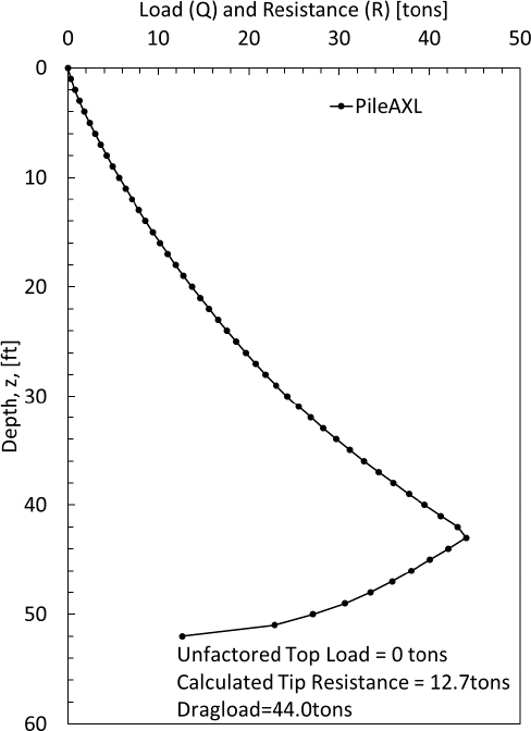
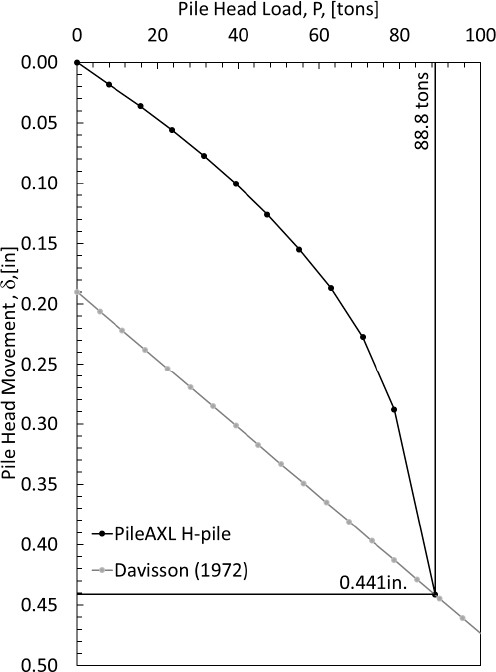
Table J4. Load-settlement curve data.
| δhead | Qhead | Comments: δhead=Pile head movement, Qhead=Pile head load |
| [in] | [tons] | |
| 0.000 | 0.0 | |
| 0.018 | 7.9 | |
| 0.036 | 15.7 | |
| 0.056 | 23.6 | |
| 0.077 | 31.5 | |
| 0.100 | 39.3 | |
| 0.126 | 47.2 | |
| 0.155 | 55.1 | |
| 0.187 | 62.9 | |
| 0.227 | 70.8 | |
| 0.288 | 78.7 | |
| 0.441 | 88.8 |
Conclusion:
The influence of the hard layer that the pile was tipped into caused the neutral plane to be located closer to the tip of the pile. Inputs for the maximum end bearing resistance and maximum unit side for dolomite obtained from the Illinois Department of Transportation (2009) were input for the analyses. From the PileAXL analyses, the neutral plane was determined to occur at a depth of 43 feet, a drag load of 44 tons.
References
Budge, A.S. Dasenbrock, D.D. (2016). “The Downdrag Response of a Driven Pile Bridge Foundation in Minnesota.” Proceedings of GeoVancouver 2016, Vancouver, British Columbia, Canada, October.
Ensoft (2021). “TZPILE v. 2021”. Software Program.
Illinois Department of Transportation. (2009). “Axial Geotechnical Resistance of Driven Piles.” 10 pgs.
Innovative Geotechnics Pty Ltd. (2023). “PileAXL 2.5: A Program for Single Piles Under Axial Loading”. Software Program.
Kulhawy, F.H. and Mayne, P.W. (1990). Manual on Estimating Soil Properties for Foundation Design. Electric Power Research Institute EL-6800, Project 1493-6, Electric Power Research Institute, Palo Alto, CA


