Investigation and Mitigation of Insulated Joint Electrical Failure: A Guide (2025)
Chapter: Appendix B: Proposed Solutions

APPENDIX B
Proposed Solutions
Purpose
One objective of the TRB TCRP Project D-20, “Investigation and Mitigation of Insulated Joint Electrical Failure” was to determine the best mitigation of insulated joint (IJ) electrical failures. This appendix summarizes some of the innovative solutions found during the development of this report, Investigation and Mitigation of Insulated Joint Electrical Failure: A Guide. The conditions that can lead to IJ arcing can have more than one root cause and may require extensive modifications and efforts to implement. There is no single solution to mitigate IJ arcing.
Background
IJs are special rail splices that mechanically connect rail ends and electrically isolate the connected rails. The electrical separation in rails provided by IJs is required for the train control (signaling) systems that govern train operations and prevent conflicts in the movements of trains. IJs are also used to isolate traction power negative return (TPNR) in adjacent track segments. Different devices and strategies used to allow TPNR to bypass the IJs should still provide electrical isolation between the rail ends required for the train control systems.
Electrified railways experiencing the IJ arcing covered in this study distribute the electric traction power as direct current (DC) using either contact (third) rail or overhead contact wire/catenary (OHC) systems. Some properties have trains that use alternating-current (AC) traction motors. On these trains, the DC power collected from the traction power system is converted to AC power onboard the trains to power the AC traction motors that drive the trains. Any power drawn by trains from a particular traction power substation (TPSS) must be returned to that same TPSS. Traction power is returned to TPSSs primarily using the running rails of the tracks, in addition to cables and bonding (cable connections). This return circuit is called TPNR.
TPNR is not the same as an electrical earth ground; it is a separate electrical circuit. Electrical potential difference exists between the TPNR and earth, and the difference in electrical energy can be significant at tens of volts and thousands of amps or more. TPNR systems are electrically isolated from earth ground to control stray currents that can damage the rail and adjacent electrically conductive infrastructure.
After the introduction of new vehicle fleets with AC traction motors, some DC electric railways noted IJ failures due to electrical arcing. Electrical arcing is not normal in electrified railways and is indicative of other underlying issues. Typically, IJ arcing and associated rail damage are caused by symptoms of other issues that create excessive TPNR electrical potential differences at the rails joined by the IJs, by a mechanical or insulation failure in the IJ assemblies.
Where arcing occurs at IJs, the running rails, IJs, train control systems, and equipment on trains can be damaged, and the impacts are further compounded by delays to train operations caused by the arcing damage. While IJ arcing can occur on electrified railways with AC power distribution systems, the mitigation efforts are very different from those for DC systems and are outside the scope of this work.
Proposed Solutions
Table B-1 lists proposed solutions for IJ arcing mitigation. There is no common solution for all locations where IJ arcing may occur. In some cases, the resolution may involve extensive modifications or generate impacts to operations. Some of the solutions did not make it past the proposal stage and have never been implemented, while other proposed solutions required nonexistent technology to implement. The suggested solutions are provided to provide ideas on how to resolve or prevent IJ arcing in their situation. At a minimum, the information presented in this appendix may lead users of this guide to solutions for their unique situations and operating environments.
In Table B-1, proposed solutions are grouped by category; however, no assumptions should be made regarding how effective the solutions may be for mitigating IJ arcing in any given situation, based on the order presented. Each location is unique, and in some cases, multiple different solutions may be required to mitigate IJ arcing at a particular location. The underlying issues can be different at each location and may require other solutions. The proposed solution categories used are the following:
- Successful: Successfully implemented to mitigate IJ arcing.
- Proposed: Technically feasible but has not been implemented.
- Theoretical: Theoretical proposal that may not be feasible with existing technology or knowledge.
- Unsuccessful: Implementation did not mitigate IJ arcing.

(continued on next page)
Long Description.
The column headers are Item, Category, Proposed Solution, Description, and Notes. The data given in the table rows are as follows:
Row 1: 1; Successful; Additional Bond Cables; Increase the capacity (size or number) of bonding cables at existing bond locations. This includes bonding rail to rail, at rail ends, through special trackwork, intertrack cross-bonds, impedance bonds, and between track and TPSS. Typically, this mitigation can be easily implemented. No modifications to the train control system are required since the existing design is not changed, only enhanced. Since the installation may change the electrical properties of the track circuits, train control testing may be required after installation; adjustments may be required. Systems Possibly Impacted: None. Benefits: Reduced electrical resistance of the TPNR system in the track. Reduced rail-to-rail and track-to-track TPNR imbalances. Implementation Challenges: Cost.
Row 2: 2; Successful; Higher-Capacity Impedance Bonds; Replace existing impedance bonds with higher-capacity units; Impedance bonds have current carrying capacity limits based on their design. This option replaces existing impedance bonds with higher-capacity units. Systems Possibly Impacted: Train Control. Benefits: Reduced electrical resistance of the TPNR system in the track that can result in IJ arcing. Reduced rail-to-rail and track-to-track TPNR imbalances that can result in IJ arcing. Implementation Challenges: Cost.
Row 3: 3; Successful; Additional Impedance Bonds; Add additional impedance bonds at IJ locations; This option adds additional impedance bonds at IJ locations where they are not currently used. It also provides additional pathways for the TPNR circuit reducing imbalances in the TPNR system that can lead to arcing. This may also allow additional track-to-track cross-bonds that can further reduce the potential of IJ arcing. Systems Possibly Impacted: Train Control, Traction Power. Benefits: Reduced electrical resistance of the TPNR system in the track that can result in IJ arcing. Reduced rail-to-rail and track-to-track TPNR imbalances that can result in IJ arcing. Implementation Challenges: Cost. May not be possible with existing train control design. Possible alternate electrical (sneak) paths for train control circuit signals that can bypass safety functions and interfere with broken rail protection.
Row 4: 4; Successful; Separate Traction Power Negative Return Cable; A separate high-capacity cable that connects the TPNR busses is run along the trackway between adjacent TPSSs. Cables (taps) are connected periodically between the TPNR cable and running rails of the adjacent tracks; This option can be prohibitively expensive but has been used to address TPNR issues successfully. One transit used scrap running rails run alongside the track in lieu of cables to reduce costs. Systems Possibly Impacted: Train Control, Traction Power. Benefits: Significant reduction of electrical resistance of the TPNR system in the track that can result in IJ arcing. Reduced rail-to-rail and track-to-track TPNR imbalances that can result in IJ arcing. Implementation Challenges: Cost: requires significant capital investment. Possible alternate electrical (sneak) paths for train control circuit signals that can bypass safety functions and interfere with broken rail protection. Possible generation of radio frequency (RF) interference to neighbors, radio systems, and train control signals. Potential induced currents in other adjacent conductors. Metal conductors used may provide a lucrative target for trespassing thieves.
Row 5: 5; Successful; Increased Insulated Rail Joint End Post Thickness (Li et al. 2023.); Use three-eighths of an inch wide end posts; Typical IJ end Posts widths are as little as one-eighth inch. Three-eighths of an inch wide end posts have been used in the transit environment successfully. This solution proposed the specification and adoption of three-eighths of an inch end posts. Systems Possibly Impacted: Track. Benefits: Can increase IJs ability to resist arcing. Little or no additional cost for new IJs. Can improve IJs ability to resist IJ arcing. Implementation Challenges: IJ arcing may still occur where there is a significant difference in electrical potential between adjacent rails. Would likely require replacement of IJs at existing locations.
(continued on next page)
Long Description.
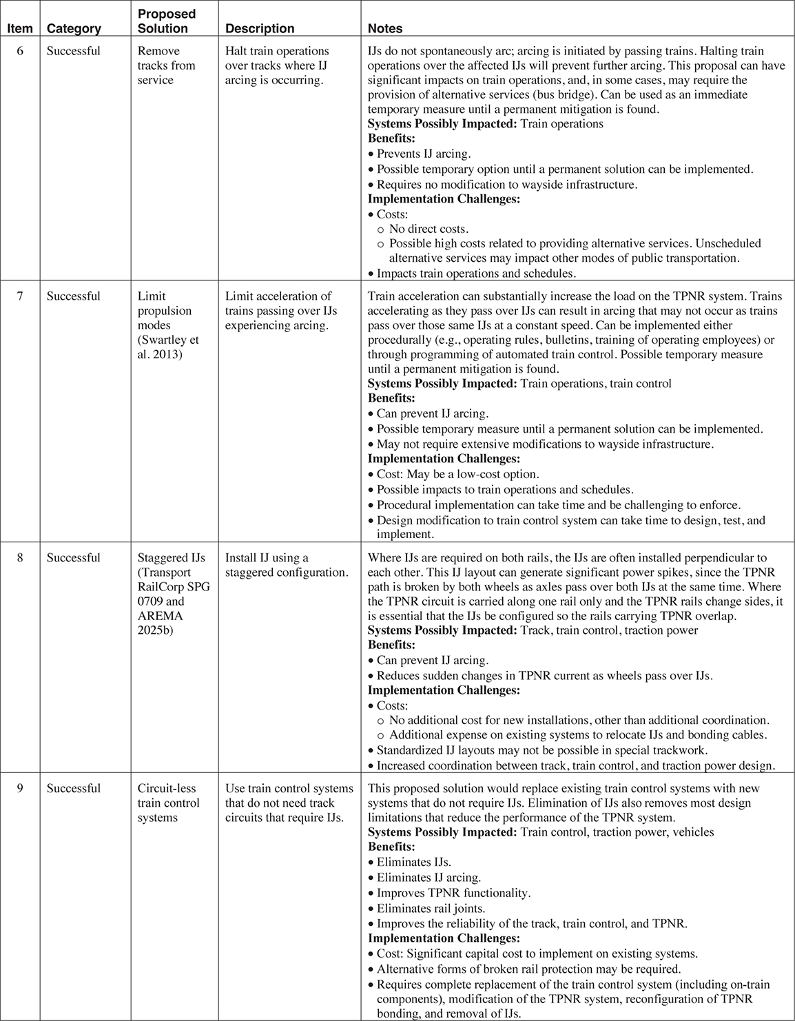
Row 6: 6; Successful; Remove Tracks from Service; Halt train operations over tracks where IJ arcing is occurring; IJs do not spontaneously arc; arcing is initiated by passing trains. Halting train operations over the affected IJs will prevent further arcing. This proposal can have significant impacts on train operations, and, in some cases, may require the provision of that alternative services (bus bridge). Can be used as an immediate temporary measure until a permanent mitigation is found. Systems Possibly Impacted: Train Operations. Benefits: Prevents IJ arcing. Possible temporary option until a permanent solution can be implemented. Requires no modification to wayside infrastructure. Implementation Challenges: Costs: No direct costs. Possible high costs related to providing alternative services. Unscheduled alternative services may impact other modes of public transportation. Impacts train operations and schedules.
Row 7: 7; Successful; Limit Propulsion Modes (Swartley et al. 2013); Limit acceleration of trains passing over IJs experiencing arcing; Train acceleration can substantially increase the load on the TPNR system. Trains accelerating as they pass over IJs can result in arcing that may not occur as trains pass over those same IJs at a constant speed. Can be implemented either procedurally (example, operating rules, bulletins, training of operating employees) or through programming of automated train control. Possible temporary measure until a permanent mitigation is found. Systems Possibly Impacted: Train Operations, Train Control. Benefits: Can prevent IJ arcing. Possible temporary measure until a permanent solution can be implemented. May not require extensive modifications to wayside infrastructure. Implementation Challenges: Cost: May be a low-cost option. Possible impacts to train operations and schedules. Procedural implementation can take time and be challenging to enforce. Design modification to train control system can take time to design, test, and implement.
Row 8: 8; Successful: Staggered Insulated Rail Joints (Transport RailCorp SPG 0709 and AREMA C and S Manual.); Install IJ using a staggered configuration; Where IJs are required on both rails, the IJs are often installed perpendicular to each other. This IJ layout can generate significant power spikes, since the TPNR path is broken by both wheels as axles pass over both IJs at the same time. Where the TPNR circuit is only carried along one rail and the TPNR rails change sides, it is essential that the IJs be configured so the rails carrying TPNR overlap. Systems Possibly Impacted: Track, Train Control, Traction Power. Benefits: Can prevent IJ arcing. Reduces sudden changes in TPNR current as wheels pass over IJs. Implementation Challenges: Costs: No additional cost for new installations, other than additional coordination. Additional expense on existing systems to relocate IJs and bonding cables. Standardized IJ layouts may not be possible in special trackwork. Increased coordination between track, train control, and traction power design.
Row 9: 9; Successful; Circuit-less Train Control Systems; Use train control system(s) that do not require track circuits that require IJs; This proposed solution would replace existing train control systems with new systems that do not require IJs. Elimination of IJs also removes the majority of design limitations that reduce the performance of the TPNR system. Systems Possibly Impacted: Train Control, Traction Power, Vehicles. Benefits: Eliminates IJs. Eliminates IJ arcing. Improves TPNR functionality. Eliminates rail joints. Improves the reliability of the track, train control, and TPNR. Implementation Challenges: Cost: Significant capital cost to implement on existing systems. Alternative forms of broken rail protection may be required. Requires complete replacement of the train control system (including on-train components), modification of the TPNR system, reconfiguration of TPNR bonding, and removal of IJs.

(continued on next page)
Long Description.
Row 10: 10; Successful; 4th Rail; Use 4th rail for TPNR; 4th rail systems use an additional rail for the TPNR. Trains receive power from the 3rd rail or OHC and the TPNR is returned to the TPSS using a 4th rail. This design is used on the London Underground. A similar concept was used on some early trolley systems, and later trolley buses, where a two-wire OHC was used, one wire for traction power and a second wire for TPNR. One proposed application (Swartley et al. 2013) was to install 4th rail only through areas where IJ arcing is occurring. Systems Possibly Impacted: Track, Train Control Traction Power, Vehicles. Benefits: Eliminates IJs. Separates train control and TPNR systems, eliminating conflicts and compromises between the two systems. Implementation Challenges: Cost: Significant capital costs for implementation. Transit vehicles must also be modified. Eliminates interfaces between train control and TPNR. Track design is more complex, 4th rail adds additional impediments to wayside maintenance. Additional wayside and on-vehicle systems to install and maintain. Arcing, same that occurs on collector shoes at the ends of 3rd rail, will still occur at the ends of the 4th rail segment when train return paddles drop off.
Row 11: 11; Successful; Larger Rail; Replace running rails with a larger rail section; The current carrying capacity of the rail is related to its size (weight per yard divided by cross section). Increased rail size will reduce the in-track resistance that can result in imbalances in the TPNR system and lead to IJ arcing. See Appendix D. Systems Possibly Impacted: Benefits: Reduction in the electrical resistance of the TPNR system in the track. Reduced rail-to-rail and track-to-track TPNR imbalances. Reduction in track maintenance cycles. Improved track reliability. Implementation Challenges: Cost: The cost of replacing existing rail can be expensive. May also require replacement of ties and fastening systems. Larger rail will increase initial costs for new systems. May not be feasible where large rail sections are already used.
Row 12: 12; Successful; CWR; Use continuously welded rail (CWR), in lieu of jointed rail; Each rail joint in the track impedes the flow of TPNR through the running rails. While rail joints are bonded, these bonds add resistance in the rail can result in imbalances in the TPNR system that can lead to IJ arcing. Rail joints also impact the reliability of the train control and TPNR systems since the additional bonding required at each rail joint can fail resulting in performance and reliability issues. The use of CWR is the current industry best practice and is generally used on new systems. On existing systems, replacing the existing jointed rail with CWR may reduce the incidence of IJ arcing. Systems Possibly Impacted: Track. Benefits: Reduced resistance of the TPNR system in the track. Reduced rail to rail and track to track TPNR imbalances. Reduction in track maintenance cycles. Improved track reliability. Can be implemented during planned rail replacement activities. Implementation Challenges: Cost: Replacing rail or welding of existing rail joints can be a significant capital cost.

(continued on next page)
Long Description.
Row 13: 13; Proposed; Limit Number of Trains; Reduce the number of trains passing through areas experiencing IJ arcing; The loads on TPNR system are increased where more trains are simultaneously operated. The increased loads may create imbalances in the TPNR system that can lead to arcing at IJs. Reducing the number of trains operating simultaneously in the area where IJ arcing is occurring can reduce the load on the TPNR system, possibly eliminating scenarios where IJ arcing can occur. Can be implemented either procedurally (example, through operating rules, bulletins, training of operating employees) or through programming of automated train control. Possible temporary measure until permanent mitigation can be implemented. Systems Possibly Impacted: Train Operations, Train Control. Benefits: Can provide immediate mitigation for IJ arcing. Possible temporary option until a permanent solution can be implemented. Implementation Challenges: Cost: May be a low-cost option. Impacts on schedule and overall system capacity. Design modification to train control system can take time to design, test, and implement.
Row 14: 14; Proposed; Reduce Consist Lengths; Reduce the length of train consists passing over, and or simultaneously operating in the area of, IJs experiencing arcing; The train length increases the loads on the TPNR system. Longer trains can generate higher electrical imbalances in the TPNR system that can lead to IJ arcing. Reducing the lengths of the consists operating over affected IJs may mitigate arcing and might be easily implemented. Can be used as a temporary measure until a permanent mitigation is found. Systems Possibly Impacted: Train Operations. Benefits: Can provide immediate mitigation to IJ arcing. Possible temporary option until a permanent solution can be implemented. Implementation Challenges: Cost: May be a low-cost option. Impacts schedule and overall system capacity. Can impact comfort of riders because of overcrowding.
Row 15: 15; Proposed; Restrict Movement Over IJs; Restrict operation of trains over IJs experiencing arcing, when there are other trains in the area; This option proposes reducing the TPNR system loads that contribute to IJ arcing by restricting the movement of trains over IJs when there are other trains in the area, possibly eliminating scenarios where IJ arcing can occur. Can be implemented either procedurally (example, through operating rules, bulletins, training of operating employees) or through programing of automated train control. Possible temporary measure until a permanent mitigation is found. Systems Possibly Impacted: Train Operations. Benefits: Can provide immediate mitigation to IJ arcing. Possible temporary option until a permanent solution can be implemented. Implementation Challenges: Cost: May be a low-cost option. Impacts on schedule and overall system capacity. Design modification to train control system can take time to design, test, and implement.
Row 16: 16; Proposed; Reduce Train Speeds; Reduce the speed of trains in the vicinity of IJs experiencing arcing; Higher train speeds increase the loads that can contribute to the arcing of IJs on the TPNR system. This option proposes reducing the TPNR system loads that contribute to IJ arcing by reducing the speed of trains operating in the vicinity of the arcing IJs. Can be implemented either procedurally (example, through operating rules, bulletins, training of operating employees) or through programing of automated train control. Possible temporary measure until a permanent mitigation is found. Systems Possibly Impacted: Train Operations. Benefits: Can provide immediate mitigation to IJ arcing. Possible temporary option until a permanent solution can be implemented. Implementation Challenges: Cost: May be a low-cost option. Impacts on schedule and overall system capacity.
(continued on next page)
Long Description.
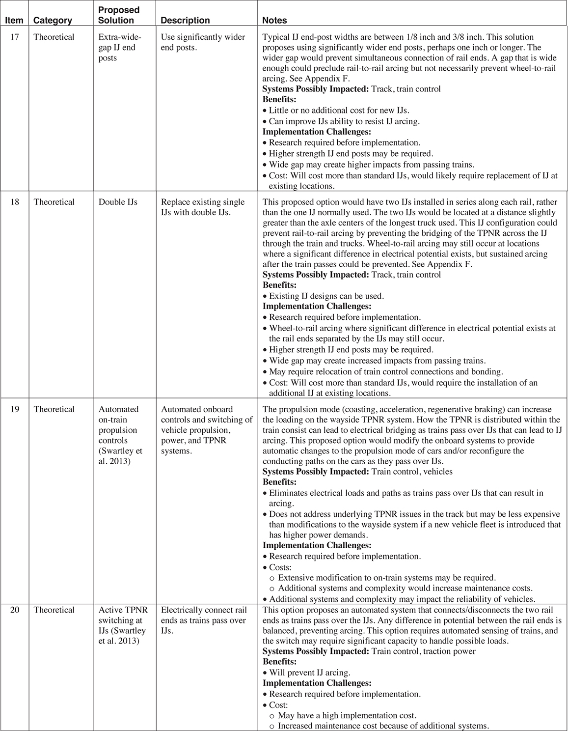
Row 17: 17; Theoretical; Extra-Wide-Gap IJ End Posts; Use significantly wider end posts; Typical IJ end posts widths are between 1 by 8 inch and 3 by 8 inch. This solution proposes using significantly wider end posts, perhaps 1 inch or longer. The wider gap would prevent simultaneous connection of rail ends. A wide-enough gap could preclude rail-to-rail arcing but not necessarily prevent wheel-to-rail arcing. See Appendix F. Systems Possibly Impacted: Track, Train Control. Benefits: Little or no additional cost for new IJs. Can improve IJs ability to resist IJ arcing. Implementation Challenges: Research required prior to implementation. Higher strength IJ end posts may be required. Wide gap may create higher impacts from passing trains. Cost: Will cost more than standard IJs, would likely require replacement of IJ at existing locations.
Row 18:18; Theoretical; Double IJs; Replace existing single IJs with double IJs; This proposed option would have two IJs installed in series along each rail, rather than the one IJ normally used. The two IJs would be located at a distance slightly greater than the axle centers of the longest truck used. This IJ configuration could prevent rail-to-rail arcing by preventing the bridging of the TPNR across the IJ through the train and trucks. Wheel-to-rail arcing may still occur at locations where a significant difference in electrical potential exists, but sustained arcing after the train passes could be prevented. See Appendix F. Systems Possibly Impacted: Track, Train Control. Benefits: Existing IJ designs can be used. Implementation Challenges: Research required prior to implementation. Wheel-to-rail arcing where significant difference in electrical potential exists at the rail ends separated by the IJs may still occur. Higher strength IJ end posts may be required. Wide gap may create increased impacts from passing trains. May require relocation of train control connections and bonding. Cost: Will cost more than standard IJs, would require the installation of an additional IJ at existing locations.
Row 19: 19; Theoretical; Automated On-Train Propulsion Controls (Swartley et al. 2013.); Automated onboard controls and switching of vehicle propulsion, power, and TPNR systems; The propulsion mode (coasting, acceleration, regenerative braking) can increase the loading on the wayside TPNR system. How the TPNR is distributed within the train consist can lead to electrical bridging as trains pass over IJs that can lead to IJ arcing. This proposed option would modify the on-board systems to provide automatic changes to the propulsion mode of cars and or reconfigure the conducting paths on the cars as they pass over IJs. Systems Possibly Impacted: Train Control, Vehicles. Benefits: Eliminates electrical loads and paths as trains pass over IJs that can result in arcing. Does not address underlying TPNR issues in the track but may be less expensive than modifications to the wayside system if a new vehicle fleet is introduced that has higher power demands. Implementation Challenges: Research required prior to implementation. Costs: Extensive modification to on-train systems may be required. Additional systems and complexity would increase maintenance costs. Additional systems and complexity may impact the reliability of vehicles.
Row 20: 20; Theoretical; Active TPNR Switching at IJs (Swartley et al. 2013.); Electrically connect rail ends as trains pass over IJs; This option proposes an automated system that connects or disconnects the two rail ends as trains pass over the IJs. Any difference in potential between the rail ends is balanced, preventing arcing. This option requires automated sensing of trains, and the switch may require significant capacity to handle possible loads. Systems Possibly Impacted: Train Control, Traction Power. Benefits: Will prevent IJ arcing. Implementation Challenges: Research required prior to implementation. Cost: May have a high implementation cost. Increased maintenance cost because of additional systems.

(continued on next page)
Long Description.
Row 21: 21; Theoretical; Passive IJ Shunts IJs (Swartley et al. 2013.); Passive electrical circuit between the rail ends at IJs; This option proposes an electrical circuit that senses the voltage differential between the rail ends at IJs and electrically connects the rail ends when excessive voltage levels exist as trains pass. This concept is similar to the “Active TPNR Switching” option but differs by using a solid state (non-mechanical) system. Systems Possibly Impacted: Train Control, Traction Power. Benefits: Will prevent IJ arcing. Implementation Challenges: Research required prior to implementation. May have negative impacts on train control system. May require additional circuitry and logic to coordinate with the train control system. Cost: May have a high implementation cost. Increased maintenance cost because of additional systems.
Row 22: 22; Theoretical; Variable Resistance IJs (Swartley et al. 2013.); Use special materials that have variable electrical resistance properties for the running rails; This option proposes replacing the steel running rails at IJs with rails made of special materials whose properties would provide for variable electrical resistance based on the distance from the ends of the running rails at IJs. These special materials might prevent the sudden break in the TPNR circuit that occurs when train wheels pass over an IJ with excessive electrical potential differences between the rail ends. This gradual change may prevent arcing between the train wheels and provide time for the current loads to move to alternate paths. Systems Possibly Impacted: Track. Benefits: May prevent I J arcing. Implementation Challenges: Research required prior to implementation. Materials with the required properties may not currently exist that can withstand the high wheel rail contact forces and train loads. Costs: May have a high implementation cost. Would require the replacement of existing IJs.
Row 23: 23; Theoretical; Mechanical Bridging at IJs (Swartley et al. 2013 and Bi et al. 2013); Use a mechanical system that electrically connects the rail ends, through the train wheels, as the trains pass over IJs; This concept uses a mechanism or assembly that allows passing train wheels to electrically connect the two rail ends at IJs. One end of this assembly would be connected to one of the rail ends and isolated from the adjoining rail end. As trains pass, the connection between the rail ends would still occur through the train wheels but would be provided through the mechanism, not the running surface of the rail. Arcing would still occur when the connection is broken, but this concept would move the arcing off the running surface of the rail, thereby preventing destructive arcing that impacts the integrity of the running rail. Since this mechanism is not carrying the train loads, materials that can provide a variable resistance that could possibly dampen or prevent arcing may exist. Systems Possibly Impacted: Train Control, Traction Power. Benefits: May prevent IJ arcing. Implementation Challenges: Research required prior to implementation. Costs: May have a high implementation cost. May require the replacement of existing IJs. Increased maintenance cost because of additional systems.
Long Description.
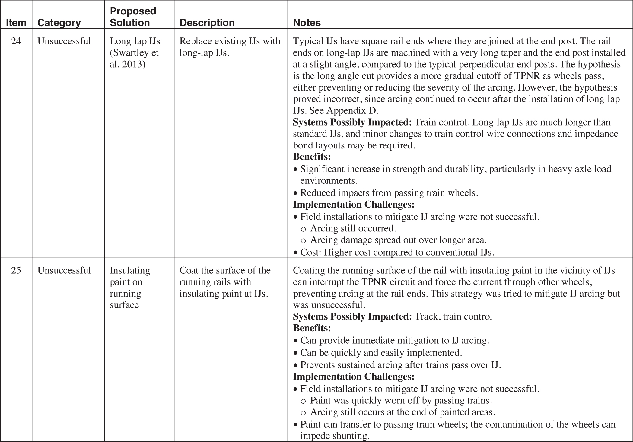
Row 24: 24; Unsuccessful; Long-Lap Insulated Rail Joint (Swartley et al. 2013); Replace existing IJs with long-lap IJs; Typical IJs have square rail ends where they are joined at the end post. The rail ends on long-lap IJs are machined with a very long taper and the end post installed at a slight angle, compared to the typical perpendicular end posts. The hypothesis is the long angle cut provides a more gradual cutoff of TPNR as wheels pass, either preventing or reducing the severity of the arcing. However, the hypothesis proved incorrect, since arcing continued to occur after the installation of long-lap IJs. See Appendix D. Systems Possibly Impacted: Train Control. Long-lap IJs are much longer than standard IJs, and minor changes to train control wire connections and impedance bond layouts may be required. Benefits: Significant increase in strength and durability, particularly in heavy axle load environments. Reduced impacts from passing train wheels. Implementation Challenges: Field installations to mitigate IJ arcing were not successful. Arcing still occurred. Arcing damage spread out over longer area. Cost: Higher cost compared to conventional IJs.
Row 25: 25; Unsuccessful; Insulating Paint on Running Surface; Coat the surface of the running rails with insulating paint at IJs; Coating the running surface of the rail with insulating paint in the vicinity of IJs can interrupt the TPNR circuit and force the current through other wheels, preventing arcing at the rail ends. This strategy was tried in an attempt to mitigate IJ arcing but was unsuccessful. Systems Possibly Impacted: Track, Train Control. Benefits: Can provide immediate mitigation to IJ arcing. Can be quickly and easily implemented. Prevents sustained arcing after trains pass over IJ. Implementation Challenges: Field installations to mitigate IJ arcing were not successful. Paint was quickly worn off by passing trains. Arcing still occurs at the end of painted areas. Paint can transfer to passing train wheels; the contamination of the wheels can impede shunting.
This page intentionally left blank.


