Investigation and Mitigation of Insulated Joint Electrical Failure: A Guide (2025)
Chapter: 6 Case Studies

CHAPTER 6
Case Studies
This chapter provides a variety of examples of TPNR-induced arcing incidents experienced on electrified railways and the mitigations implemented to address the arcing. Some of the following case studies are composites of issues from multiple transits, compiled to provide clear examples of problems and mitigations. The intent is to provide insights on methods and strategies that may aid in determining the best mitigation(s) for the unique environment. It may not always be feasible to directly address the root causes of an arcing issue; however, understanding all the items contributing to the issue will provide the information needed to develop the best mitigation strategy.
The following are some key points to keep in mind when reviewing these case studies and in addressing arcing issues:
- Consider each arcing location to be unique.
- Look for similarities between multiple arcing locations only after understanding what is contributing to arcing at each location.
- Differences in TPNR electrical potential are normal at insulation locations.
- A high-enough TPNR electrical potential must exist at insulation locations to initiate destructive arcing.
- The level of damage increases as the amperage increases.
- All contributing factors should be understood.
- The best strategy may not address the root cause but can mitigate the arcing.
- TPNR is a dynamic environment—voltages, polarity, and amperage vary constantly, even under passing trains.
- The TPNR electrical environment is heavily influenced by the train traffic in the area.
By studying real-life examples of TPNR-induced arcing incidents and the corresponding mitigations, users of this guide may gain insight on how to effectively address arcing issues on their electrified railway systems. Learning from the experiences of others provides a better understanding of potential causes of arcing; users can develop the best strategies to prevent and mitigate the issues in their own specific situations. Ultimately, the goal is to find the most cost-effective mitigation that can be applied with the available resources.
This chapter provides some examples—but not necessarily an example for every possible solution—and should be used in conjunction with Appendix B. However, there will be many similarities in the steps required to determine the best solution for IJ arcing issues that guide users may encounter.
Case Study 1: Pocket Track Crossover Insulated Joint Arcing
Description
IJ arcing was discovered at one IJ location 8 years after a new line had been placed in service. Extensive dynamic testing was performed before opening the tracks, and no issues were
encountered. Because of construction activities miles away from the location of the IJ, trains were single-tracking through the area, which required them to cross over from one main line track to another through a pocket track. The track in this area uses concrete ties in open track, wood ties on turnouts, and continuously welded rail (CWR) except at IJs (see Figure 14).
Issue
Indications of IJ arcing were initially identified when train control technicians were dispatched to troubleshoot a false occupancy in the track. Their investigation identified a failed IJ, and track crews were dispatched to repair the IJ. Weeks later, a failed IJ was again identified as the cause of another false occupancy issue in the same area, and track crews were able to grind the rail ends of the IJ to correct the train control failure. After a third event, a more extensive effort was initiated to address the reoccurring issue.
Investigation
During the investigation, employees found that IJ arcing occurred only during a unique sequence of events. Normally, trains cross over on the pocket track at constant speed. However, if a train happened to stop before the crossover, it would accelerate over the IJ located on a 3 percent upgrade, and arcing would occur. Arcing would occur only with trains that had longer consists and only after the last axle of the train passed over the IJ. A combination of heavy train acceleration and trains with long consists were required for arcing to occur. In some cases, arcing between rail ends would continue after the train passed the IJ and would continue until the last axle of the train passed over the next IJ along the same rail.
The initial review of the as-built drawings showed no obvious issues that could result in IJ arcing. Field inspections found that the track, traction power, and train control drawings did not match actual field conditions. A key missing item was an intertrack cross bond shown on the drawings but not installed in the field. Later research into construction records found that the cross bond interfered with the functionality of the train control system, so the cross bond was removed. This removal occurred after the completion of the track and traction power system installations, after the submission of the as-built drawings, and after the demobilization of the track and traction power design and construction teams. Additional discrepancies found between the train control drawings had to be investigated, and the related drawings had to be updated before the final mitigation could be implemented. Unnecessary IJs that had been bonded around were found in the track, evidently because the IJ locations were shifted during construction. The abandoned IJs were simply bonded around rather than being removed, resulting in additional (unnecessary) resistance in the TPNR path. The removal of this cross bond resulted in a significantly longer
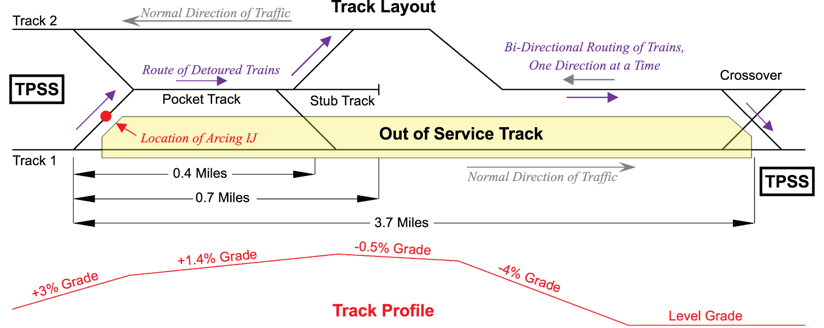
Long Description.
The track layout shows a pocket track and a stub track between Track 2 at the top (normal direction of traffic to the left) and Track 1 at the bottom (normal direction of traffic to the right). Track 1 is depicted as 3.7 miles long with a stub track to 0.7 miles and a pocket track to 0.4 miles. A location of arcing IJ is indicated on the crossover between Track 1 and the pocket track. Each track end is marked TPSS. A crossover is near the right end. The track profile at the bottom shows an upward sloping part on the left marked plus 3 percent grade followed by a part with smaller slope marked plus 1.4 percent grade, a slightly declining part marked negative 0.5 percent grade, a declining part marked negative 4 percent grade, and a horizontal line on the right marked level grade.
(higher resistance) electrical path for the TPNR on the leading rail of the IJ, compared to the trailing rail end (see Table 2 and Figure 15).
Resolution
The investigation determined that long trains accelerating from a stop generated a significant difference in TPNR voltage when passing over the IJ; this was due to the significant difference in resistance in the TPNR path on each side of the IJ. Since IJ arcing was not found at other IJs in the area, the resistance in the TPNR path on the leading end of the IJ (furthest from the TPSS) was determined not to be an issue but rather the difference in voltage created at the IJ in question.
The solution implemented was to add two rail-to-rail cross bonds at the IJ location. Additional rail-to-rail cross bonds were added on the opposite crossover, which had an identical TPNR configuration, to prevent similar IJ arcing from occurring. Required modifications to the train control system included field wiring and interlocking logic to facilitate additional cross bonds.
Before implementing the changes, operational restrictions that precluded excessive acceleration for stopped trains were placed on trains. These restrictions required a temporary 10-miles-per-hour (mph) speed limit when passing over the IJ. Figure 16 details the locations where additional cross bonding was added. After this location was mitigated, the rest of the system was surveyed for other similar situations, with a particular focus on the construction that occurred at the same time as where the arcing IJ was found.
Lessons Learned
- Changes in the TPNR design and layout should be coordinated between track, train control, and traction power.
- As-built drawings do not always reflect actual field conditions.
- Unnecessary IJs should be removed, not just bonded around, except for temporary mitigations.
- Maintenance crews were unaware that IJ arcing could not be mitigated by replacement of the IJ.
- A multidisciplinary team was required to investigate and mitigate the IJ arcing.
- A combined multidiscipline drawing was required to determine the root causes and mitigation.
- Communications with transportation operations were required to troubleshoot the conditions that caused arcing.
- TPNR layouts that have significantly different return paths, divided by an IJ, can lead to arcing.
- If IJ arcing is found at one location, then other locations should be investigated for the same conditions that led to the IJ arcing at the initial location.
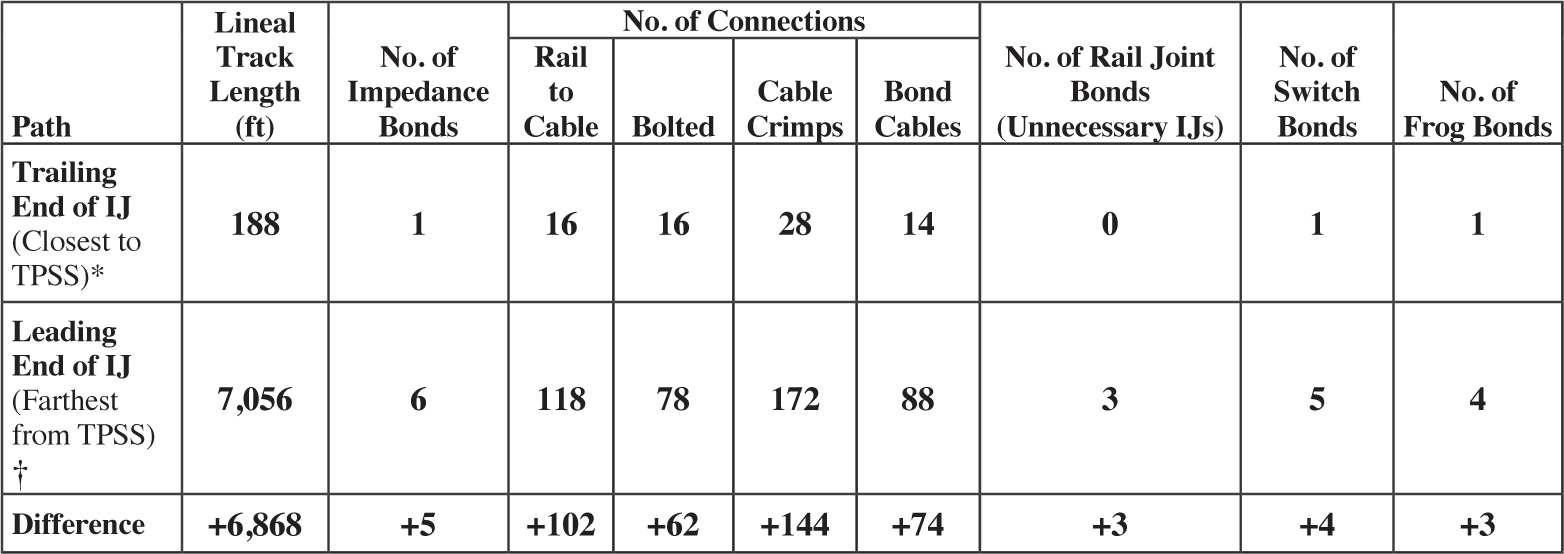
Notes: ft = feet, No. = number.
*Correlates to “Path from trailing rail end of arcing IJ to TPSS” in Figure 15.
†Correlates to “Shortest path from leading rail end of arcing IJ to TPSS” in Figure 15.
Long Description.
A table depicts distances from arcing IJ to TPSS. Two paths are shown. The first path is the trailing end of IJ (closest to TPSS, which correlates to path from trailing rail end of arcing IJ to TPSS in Figure 15). Lineal track length is 188 feet. Number of impedance bonds is 1. Number of connections, by type, is 16 rail to cable, 16 bolted, 28 cable crimps, and 14 bond cables. Number of rail joint bonds (unnecessary IJs) is zero. Number of switch bonds is 1. Number of frog bands is 1. The second path is the leading end of IJ (farthest from TPSS, which correlates to shortest path from leading rail end of arcing IJ to TPSS in Figure 15). Lineal track length is 7,056 feet. Number of impedence bonds is 6. Number of connections, by type, is 118 by rail to cable, 78 bolted, 172 cable crimps, and 88 bond cables. Number of rail joint bonds (unnecessary IJs) is 3. Number of switch bonds is 5. Number of frog bonds is 4. The difference between the two paths in each category is as follows: lineal track length, +6,868; number of impedance bonds, +5; number of connections, by type, rail to cable, +102, bolted, +62, cable crimps, +144, bond cables, +74; number of rail joint bonds (unnecessary IJs) is +3; number of switch bonds is +4; and number of frog bonds is +3.
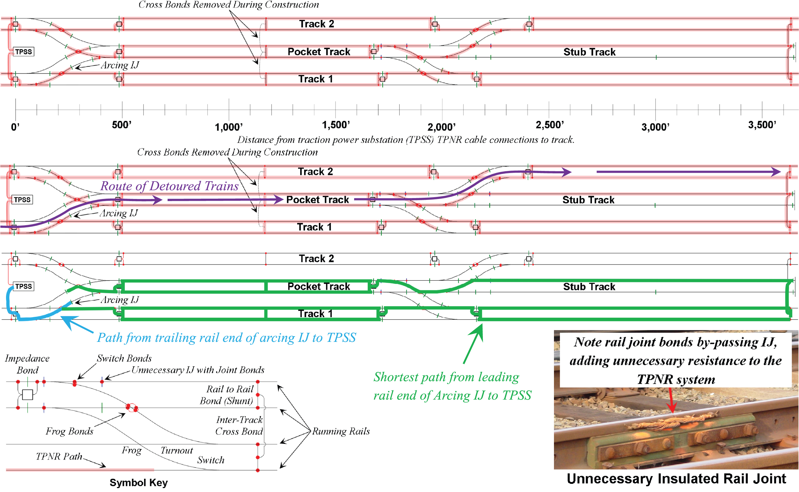
Long Description.
The illustration at the top shows a pocket track and a stub track between Track 2 at the top and Track 1 at the bottom along a horizontal axis for distance from traction power substation (TPSS) TPNR cable connections to track ranging from 0 to 3,500 feet in increments of 500 feet. The arcing IJ is on the left. The next illustration shows a similar layout with the route of detoured trains highlighted. The third illustration shows a similar layout with the path from the trailing rail end of arcing IJ to TPSS and the shortest path from the leading rail end of arcing IJ to TPSS highlighted. The next part shows key symbols as the TPNR path, frog bonds, switch bonds, impedance bond, and running rails. The photo shows an unnecessary insulated rail joint. The text reads, note rail joint bonds by-passing IJ, adding unnecessary resistance to the TPNR system.
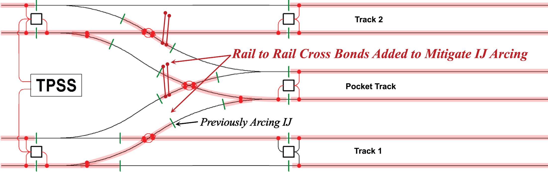
Long Description.
The illustration shows a pocket track between Track 2 at the top and Track 1 at the bottom with rail-to-rail cross bonds added to mitigate IJ arcing. The TPSS is on the left.
Case Study 2: Connections Between Electrified and Nonelectrified Railroads
Description
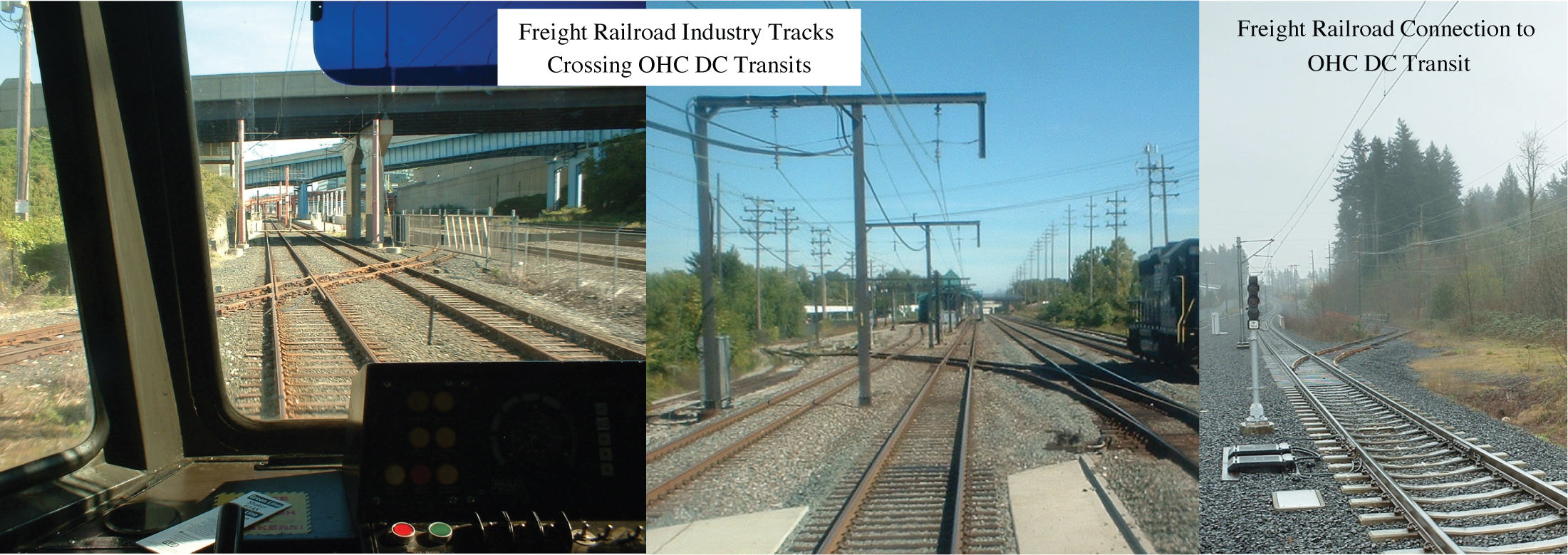
Case Study 2 highlights issues with level crossings and connections between unelectrified freight railroad industrial spurs and electrified transit tracks. The freight tracks tend to be little used industrial spurs or connecting tracks from an adjacent freight railroad to the transit for delivery of equipment and materials. Freight movements to or over electrified transit tracks are typically scheduled in advance and performed outside of the transit systemʼs regular service hours. Traction power is typically powered off during freight movements (see Figure 17).
Issue
In this case studyʼs examples, sparking is noted as freight traffic crosses over or onto the electrified railway as the wheels on the freight equipment pass over IJs. Sparking can also occur
Long Description.
The photo on the left shows the rail tracks from the interior of a rail engine with some control buttons visible in the front. The second photo shows electrified tracks. The text for these two photos reads freight railroad industry tracks crossing OHCDC transits. The third photo shows a track with side light poles and cables. The text reads, freight railroad connection to OHCDC transit.
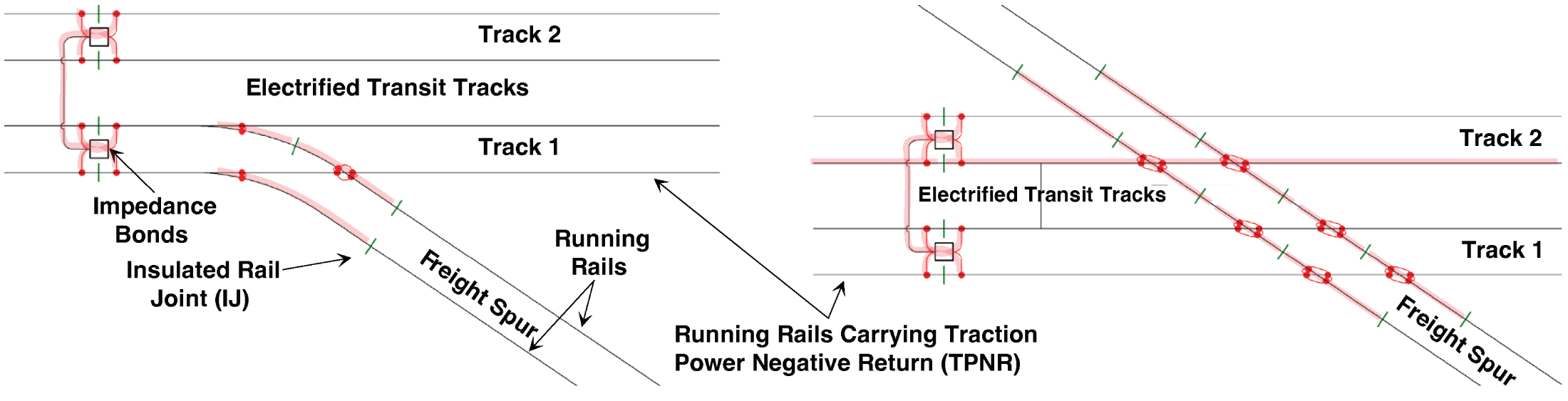
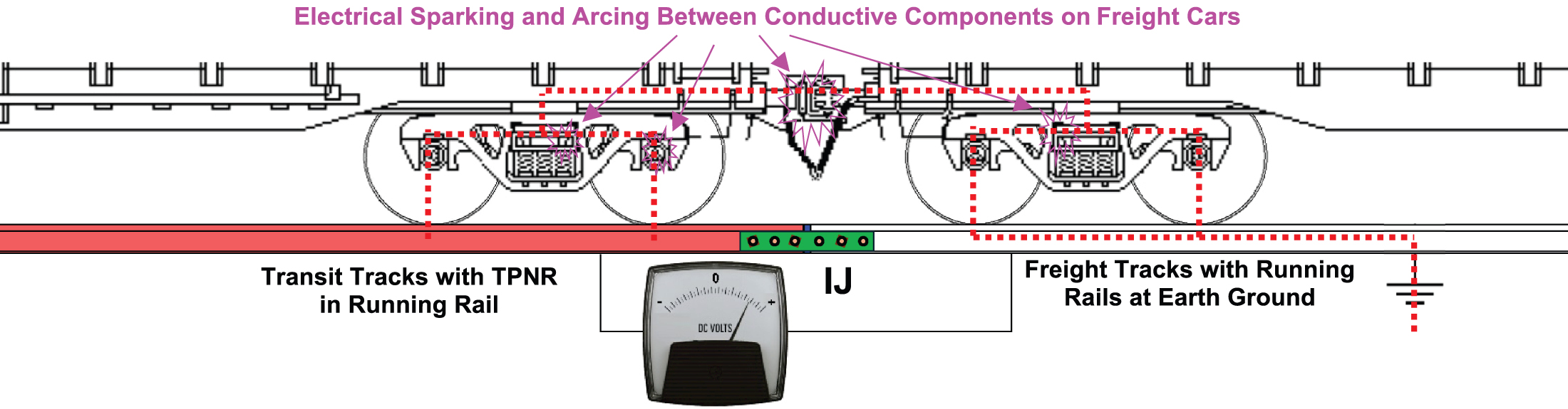
within truck assembly components, between couplers and other components on the freight cars. Because most TPNR systems are interconnected throughout wide areas on electrified railways, TPNR energy may still be present in the transit track even if electric trains are not nearby. Sparking can still occur when no transit vehicles are operating in the area and the power is turned off. The presence of TPNR can create a difference in electrical potential at the IJs separating the freight railroad and transit tracks (see Figure 18). Appendix F, Research Gaps, provides additional discussion for similar issues related to nonelectrified vehicles operating over electrified tracks.
Freight cars are electrically conductive. Typical freight cars have steel wheels that are pressed onto steel axles that provide excellent electrical conduction for shunting across the rails of the track. The axles are not electrically insulated from the truck assemblies or car-body components. However, standard freight equipment is not equipped with slip-ring systems or bonding to provide an engineered electrical path for the TPNR.
When freight equipment passes over IJs that separate the freight railroad and electrified railways, a difference in electrical potential may exist between the two rail ends, with TPNR on the transit side of the IJ and earth ground in the running rails of the freight track. A difference in TPNR potential may also exist at the IJs that separate multiple transit tracks. As the freight cars pass over these IJs, the TPNR current may attempt to go to earth ground through the freight cars, resulting in the TPNR current trying to find a pathway through the wheel bearings and truck and car components, resulting in arcing and sparking not only at the IJ but also between various freight car components. If enough TPNR current exists, freight cars may be subject to damaging arcing; wheel bearings are particularly sensitive to arcing damage (see Figure 19).
Long Description.
Each illustration shows two parallel tracks marked track 1 (bottom) and track 2 (top). The tracks are together marked as electrified transit tracks with impedance bonds to the left. The bottom rail in each illustration is marked running rails carrying traction power negative return (TPNR). In the first illustration, the running rails slope downward for the freight spur from the bottom track with an insulated rail joint (IJ). In the second illustration, a transverse running rail slopes downward for a freight spur intersecting both tracks.
Long Description.
The illustration shows transit tracks with TPNR in running rails with a meter depicting the potential difference between the rails and the ground earth. The circuit on the right shows the freight tracks with running rails at earth ground. IJ connects the transit tracks and freight tracks. Electrical sparking and arcing between conductive components on freight cars is indicated.
Potential Mitigation Considerations
While the TPNR in the running rails on electrified railways can be isolated from nonelectrified freight railroad tracks using IJs, the running rails will be electrically connected when freight cars pass over. Freight cars are electrically conductive, but most components on the freight car are neither bonded together nor designed for possible TPNR electrical loads. Each connection point between conductive freight car components can result in electrical sparking and arcing as the TPNR attempts to go to ground through the freight car. The TPNR circuit back to the TPSS can be completed through the freight equipment and running rails of the freight tracks and through stray current paths.
When dealing with such connections and crossings, TPNR leakage into the freight railroad running rails must be considered. When there are signal circuits on the adjacent freight railroad tracks, train control circuits must be protected from TPNR. Potential mitigations include the following:
- Electrical isolation sections on the freight railroad side(s) of the connection that has the freight rails well insulated from earth ground.
- Precautions must be taken if isolation sections are used, since the freight cars and freight tracks can be energized by TPNR as the freight cars pass over the transit tracks.
- Use of temporary shunts placed across rail ends at IJs when freight cars pass over the IJs.
- Temporary shunts bypass IJ insulation and balance electrical potential across the IJs.
- Care must be taken to ensure any signal systems on the freight tracks are isolated or protected from damage from TPNR that may be connected by the shunt.
- Additional shunts may be required for IJs located between rails at crossings located between multiple electrified tracks to protect them from possible differences that may exist between rails and between tracks.
- If possible, include rail-to-rail shunts on freight tracks near IJs that provide TPNR isolation to prevent possible differences in rail-to-rail electrical potential that may occur on the freight tracks.
Case Study 3: Yard Traction Power Negative Return
Description
On some electrified railways, single-rail track circuits are used in yards. Single-rail track circuits have the benefit of a single rail that, if properly configured, can provide a continuous path along one rail for TPNR, without impedance bonds. However, in this case study, the TPNR design did not provide multiple return paths for the TPNR back to the TPSS. Arcing can occur if a rail breaks or there are poor connections at bonds. Additionally, where signal and TPNR rails are transposed, IJs can be prone to arcing when not properly staggered (see Figure 20) or when the bonding scheme provides only a single path between the track and TPSS.
Issues
Electrified railways sometimes experience arcing at IJs within yards. Arcing was also noted when a broken rail occurred on the TPNR rail, when rails were removed during maintenance activities, or when rail joint bonds were broken. Additionally, there was a history of multiple water line leaks on the water lines buried within the yard.
Investigation
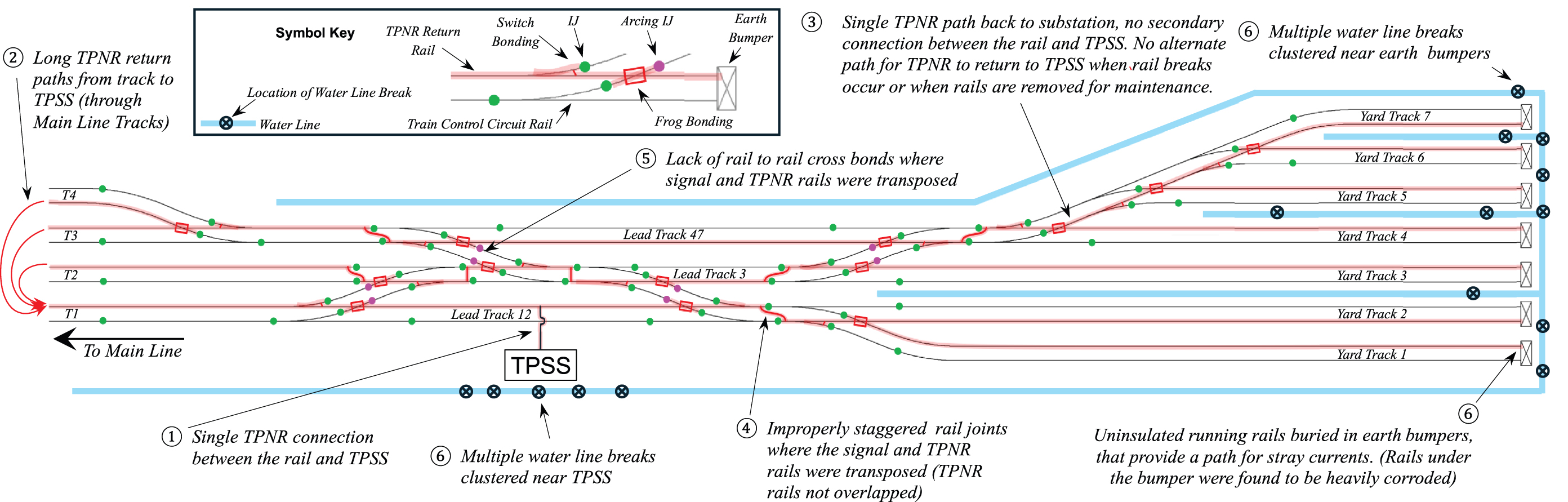
The investigation team included personnel from track, train control, traction power, and water service. A drawing was created that combined details on the layout of IJs, TPNR bonding, TPSS

Long Description.
The left photo labels are TPNR rails, TPNR rails not overlapped, rail-to-rail cross bond, and signal rails. The right photo labels are TPNR rails properly overlapped, IJ, IJ, and rail-to-rail cross bond.
TPNR return locations, TPNR rails, and signal rails (see Figure 21). The team found the following issues:
- A single TPNR connection between the rail and the TPSS.
- Long TPNR return paths between tracks and TPSS. In some cases, the only return path to the TPSS was out the main line on one yard track and back on another yard track.
- Single electrical paths in the running rails for TPNR to return to the TPSS.
- Improperly staggered rail joints where the signal and TPNR rails were transposed.
- Lack of rail-to-rail cross bonds where signal and TPNR rails were transposed.
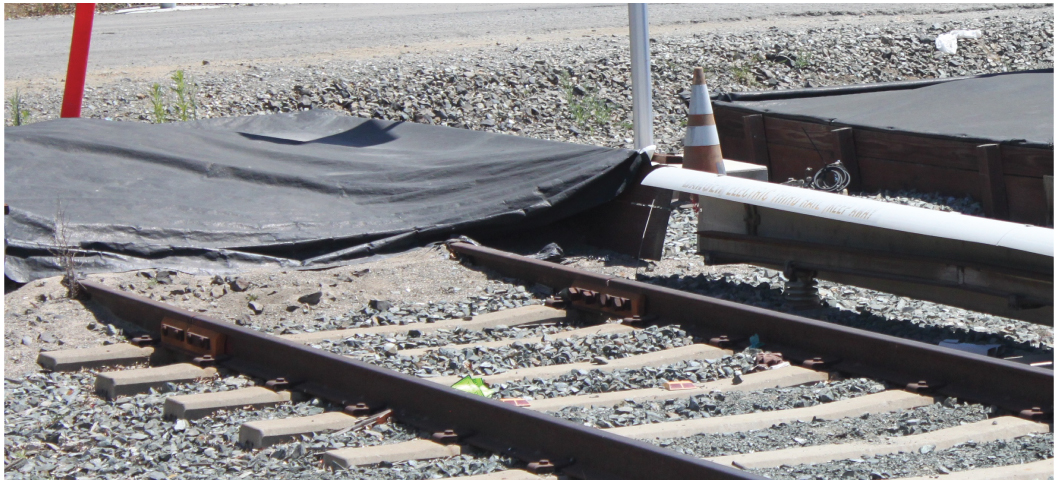
- Uninsulated running rails buried in earthen bumpers were providing a path for stray currents (see Figure 22).
The water line breaks indicated in Figure 21 were clustered around the end of track bumpers and the TPSS. The team thought that the high-resistance TPNR pathways in the running rails combined with the uninsulated TPNR running rails buried in the earthen bumpers created a situation where the easiest path for the TPNR to return to the TPSS was through the buried metal water lines. When the water lines were repaired, electrolysis corrosion was noted as the cause of the failures.
Resolution
Multiple mitigations were implemented to address the issues, including the following (see Figure 23):
- Installing IJs immediately ahead at earthen bumpers (see Figure 24).
- Staggering IJs to overlap the TPNR rails where signal and TPNR rails are transposed.
- Installing rail-to-rail bonding where signal and TPNR rails are transposed, wherever possible.
- Installing bonding between tracks to provide a minimum of two paths for the TPNR to return to the TPSS.
- Providing additional direct connections between TPNR rails and the TPSS.
Lessons Learned
- A multidisciplinary team was required to resolve the issues.
- Nonconductive pipes should be considered for buried lines near electrified railway tracks, wherever possible.
Long Description.
The illustration shows 7 parallel tracks with labels as follows. 1. Single TPNR connection between the rail and TPSS. 2. Long TPNR return paths from track to TPSS (through Main Line Tracks). 3. Single TPNR path back to substation, no secondary connection between the rail and TPSS. No alternate path for TPNR to return to TPSS when rail breaks occur or when rails are removed for maintenance. 4. Improperly staggered rail joints where the signal and TPNR rails were transposed (TPNR rail not overlapped). 5. Lack of rail-to-rail cross bonds where signal and TPNR rails were not transposed. 6. Multiple water line breaks clustered near the earth bumpers. Uninsulated running rails buried in earth bumpers that provide a path for stray currents (rails under the bumper were found to be heavily corroded). A symbol key includes indicators for location of water line, water main break, train control circuit rail, TPNR return rail, switch bonding, IJ, arcing IJ, frog bonding, and earth bumper.

- Standardized IJ layouts for turnouts and special trackwork may not always be possible to ensure proper IJ layouts to accommodate TPNR.
- The layouts of IJs must be carefully coordinated between track, train control, and traction power.
- Ideal mitigations may not be economically feasible, so less expensive alternatives must be found.
- During design and maintenance activities, ensure TPNR design and layout issues are addressed, including the following:
- Where signal and TPNR rails are transposed, the IJs should be configured to overlap the TPNR rails.
- All rails carrying TPNR should have a minimum of two pathways back to TPSS.
- Buried or embedded rails should be electrically isolated to separate the TPNR from earth ground.
Case Study 4: Maintenance Shop Insulated Joint Arcing and Touch Hazards
Description
Many vehicle maintenance facilities have the running rails in the shop buildings electrically isolated from the yard track running rails that carry TPNR. Typically, running rails in shop areas are grounded to earth to eliminate electrical touch hazards for employees working on transit vehicles and facilitate earth-grounded equipment, such as stingers (separate electrical units that provide traction power for electric vehicles in shop areas for testing), test equipment, and wheel lathes, that are grounded to earth. In this example, a third rail is used, the cars have onboard traction power, and TPNR are connected through each car but are not train-lined.
Issues
Shop employees complained of electrical shocks (touch hazards) when working on transit vehicles, reporting issues even when stingers were not in use. Additional intermittent electrical problems occurred in the shop, including tripped circuit breakers and burned wiring. The problems were attributed to failed IJs that were installed on the tracks approaching the shop facilities. Initially, shop personnel replaced IJs only on the tracks identified as problematic. The electrical issues persisted, so all IJs on tracks approaching the shop were replaced. However, the IJ replacements, unfortunately, did not mitigate the issues.
Investigation
A team was gathered that included personnel from the following areas: facility electrical, traction power, track, building maintenance, and the shop. Since the affected tracks were not signaled,
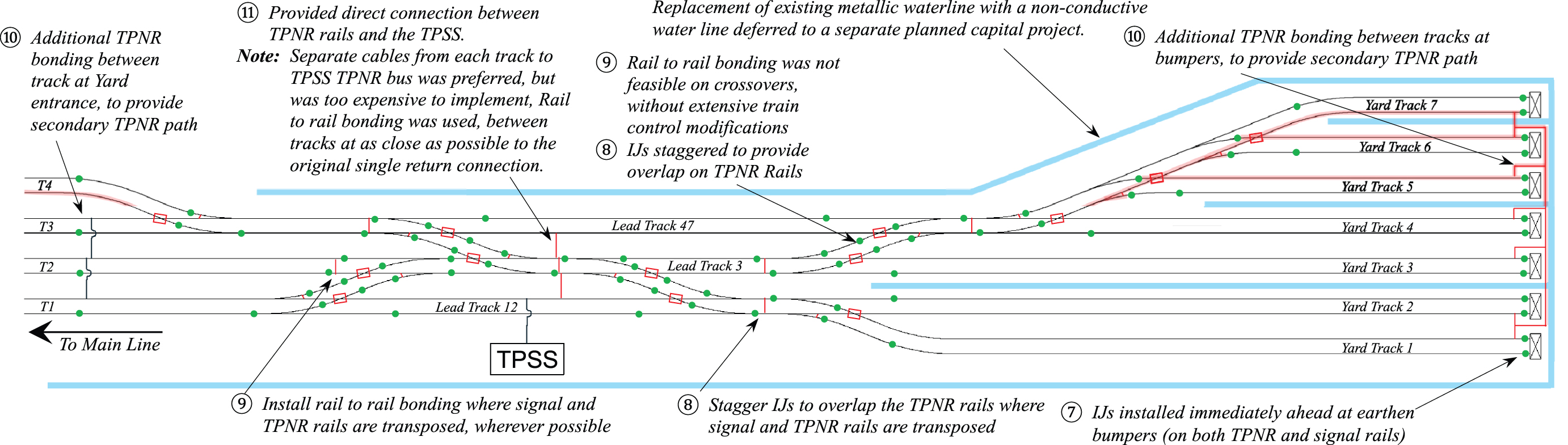
Long Description.
The illustration shows 7 parallel tracks with labels as follows. 7. IJs installed immediately ahead at earthen bumpers (on both TPNR and signal rails). 8. IJs staggered to provide overlap on TPNR rails. Stagger IJs to overlap the TPNR rails where the signal and TPNR rails are transposed. 9. Install rail-to-rail bonding where signal and TPNR rails are transposed wherever possible. Rail-to-rail bonding was not feasible on crossovers without extensive train control modifications. 10. Additional TPNR bonding between tracks at bumpers to provide a secondary TPNR path. Additional TPNR bonding between tracks at the Yard entrance to provide a secondary TPNR path. 11. Provide a direct connection between the TPNR rails and the TPSS.
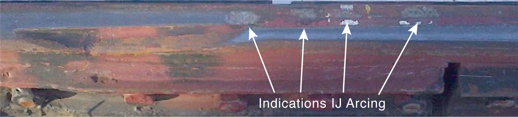
train control was not initially included. The shop facility was staffed 24 hours a day, 7 days a week, and the team scheduled multiple meetings on various days and at different times to cover all shifts and catalog all possible issues, so no shift-specific issues would be missed. During team meetings, the more-experienced shop personnel noted that previously they had experienced light electrical shocks frequently enough that getting “tingled” was considered normal and part of the job. However, it was noted that the issues had recently escalated to be almost a constant issue after the installation of a new in-floor wheel lathe that allowed wheels to be turned without dismounting the trucks. The initial consensus was that IJs were causing the issue. All the recently replaced IJs were reinspected and found to be working properly and providing good electrical isolation between the running rails; however, indications of electrical arcing were noted on some of the IJs.
The shop area was checked for grounding, and the facility grounding was found to be working well and well connected to earth ground. No breaks were found in the shop grounding grid, and a review of the original construction drawings indicated the embedded running rails in the shop area were cast directly in the concrete shop floor but not electrically bonded to the shop grounding system or to earth ground. Testing indicated that there was a weak electrical connection between the shop running rails and the shop grounding system and between the various running rails and earth ground. Poor electrical continuity also existed between the various running rails in the shop. Additional inspections found many (designed) breaks in the running rails through the shop. These breaks were located at pit swing rails, drop tables, truck turntables, the wheel lathe, and other places. Many of these components were not electrically bonded to each other or to earth ground.
The voltages between the shop and yard rails were monitored at the IJs that provided electrical isolation for the shop, and a difference in electrical potential was found across the IJs. Initially, no issues were found, but after more persistent testing, it was discovered that there would occasionally be no potential across the IJs, indicating an electrical connection between the yard TPNR and the shop rails. It was discovered that cars were being parked over the IJs, creating an electrical connection between the yard rails and shop rails, thereby allowing the TPNR to leak into the shop. While TPNR leakage may have occurred in the past, the installation of the wheel lathe changed the shop operations, and cars were more frequently parked over the IJs to facilitate the new operations.
Additionally, at some locations, the yard third rail was installed so it extended past the IJs intended for electrically isolating the shop from yard TPNR, creating situations where cars could have collector shoes on the third rail, with no electrical path for the TPNR back to the TPSS in the running rails. This connection energized the shop running rails even if the car was not moving, and TPNR was generated from auxiliary equipment on the car that was running when the car was connected to third rail. In addition to the electrical touch hazard issues, other electrical system failures attributed to the issues related to the TPNR in the shop were found (see Figure 25 and Figure 26).
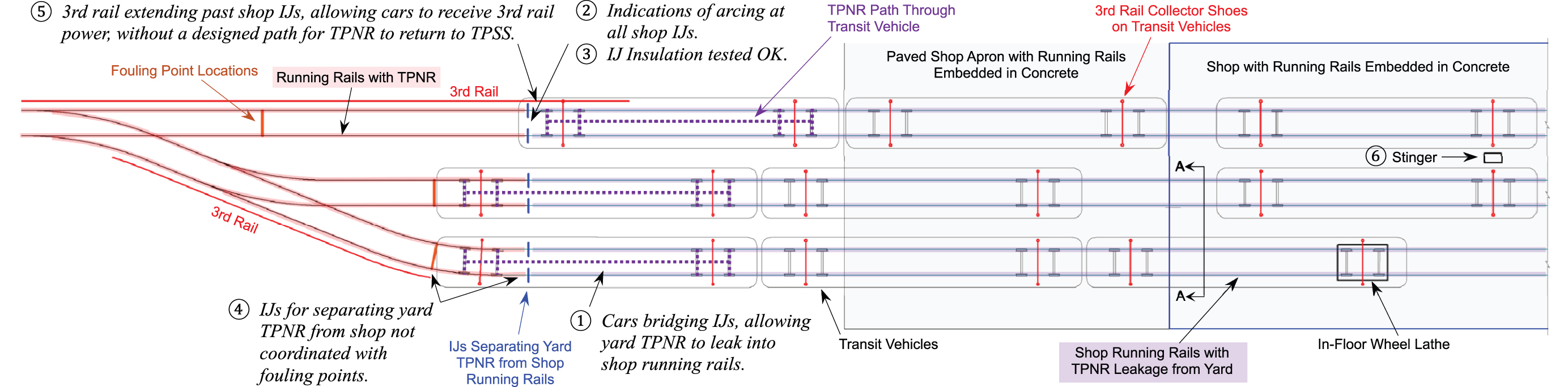
Long Description.
The illustration shows three parallel tracks with labels as follows. 1. Cars bridging IJs, allowing yard TPNR to leak into the shop running rails. 2. Indications of arcing at all shop IJs. 3. IJ installation tested OK. 4. IJs for separating yard TPNR from a shop not coordinated with fouling points. 5. Third rail extending past shop IJs, allowing cars to receive third rail power, without a designed path for TPNR to return to TPSS. 6. Stinger. The illustration also notes fouling point locations, transit vehicles, IJs separating yard TPNR from shop not coordinated with fouling points, paved shop apron with running rails embedded in concrete, shop with running rails embedded in concrete, shop running rails with TPNR leakage from yards, and in-floor wheel lathe.
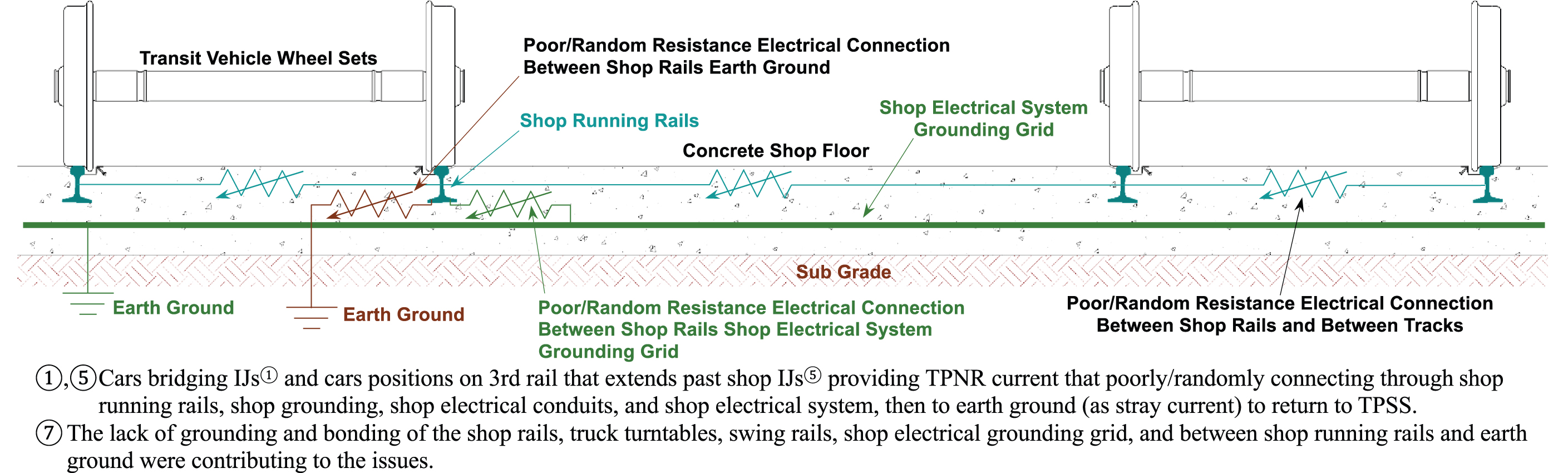
Long Description.
The illustration shows a track with transit vehicle wheel sets, each on the left and right end of the track, with a shop running rail on a concrete shop floor. The poor or random resistance electric connection between the shop rails earth ground is depicted on the left, and the poor or random resistance electric connection between the shop rails and between tracks is depicted on the right. The poor or random resistance electric connection between the shop rails shop electrical system is depicted immediately right to the first wheel sets. The circuits are earth grounded. The text reads as follows. (1), (5) Cars bridging IJs (1) and cars positions on third rail that extends past shop IJs (5) providing TPNR current that poorly or randomly connecting through shop running rails, shop grounding, shop electrical conduits, and shop electrical system, then to earth ground (as stray current) to return to TPSS. (7) The lack of grounding and bonding of the shop rails, truck turntables, swing rails, shop electrical grounding grid, and between shop running rails and earth ground were contributing to the issues.
The team determined there were multiple issues:
- Poor electrical isolation between yard TPNR and shop tracks that had existed since the shop was placed into service.
- Parked cars bridging the IJs, and thereby inadvertently creating an electrical connection between the yard TPNR and shop rails through the car. Occasionally, this had been an issue in the past, but the new operations with the wheel lathe made this a more common occurrence.
- Indications of arcing noted at IJs.
- Failed IJ insulation did not contribute to the issues.
- IJ layouts and relative locations were an issue:
- IJs for separating yard TPNR from the shop were not coordinated with fouling points. Normal locations for placing cars would force cars to be parked over IJs.
- Third-rail layouts that extended beyond the shop IJs allowed cars to receive power from the third rail with no return path back to the TPSS, creating situations where the shop rails and shop grounding system were electrically energized by cars, damaging the shop electrical system and increasing touch potentials.
- Cars parked over IJs at the same time as heavy traction power loads in the yard increased touch potential and damaged the shop electrical system.
- Stinger use contributed to the problem indirectly, not because of the stinger, but because of the lack of good electrical connection between the running rails and stinger negative connection/ground. No good electrical connection existed between the adjacent running rails and the stinger. When only a positive cable was connected to a car, the expected return was through the wheels on the car and shop running rails; the poor grounding contributed to touch hazards.
- The lack of grounding and bonding of the shop rails, truck turntables, swing rails, and shop electrical grounding grid and between shop running rails and earth ground contributed to the issues.
- Over time, modifications that electrically isolated shop running rails and did not ensure proper grounding of all components affected by the changes were made to the shop.
Initial Mitigations
The following initial mitigations were temporary operational practices implemented until permanent mitigations could be completed:
- The use of a negative jumper cable between the stinger and cars when the stinger was in use.
- Shop staff were instructed not to park cars where they could bridge the shop IJs, and affected IJs were painted for easy identification.
- Third rail that extended past IJs was temporarily isolated.
- When cars were moved over the shop IJs, personnel in the shop were warned not to touch the rail or the cars as movements over IJs occurred.
- Movements over the shop IJs were coordinated with the yard, so movements over IJs were made at times when there were few or no moves being made in the yard to reduce the possibility of excessive TPNR loads being bridged over the IJs.
Permanent Mitigations
Multiple changes were made to mitigate the issues and eliminate the need for temporary operating restrictions and practices. The approach behind the changes was to electrically interconnect all running rails in the shop and then to interconnect the shop running rails to the shop grounding grid to ensure any device within reach of the shop running rails would be equipped with a direct connection to the running rails. Priorities were to (1) eliminate touch hazards, (2) protect shop
electrical equipment from TPNR, (3) prevent cars from bridging the yard TPNR into the shop, and (4) ground all electrically conductive devices. Figure 27 includes details of these priorities:
- Stinger:
- Connection to shop grounding and earth ground verified.
- Stinger ground interconnected to rail on both adjacent tracks.
- Continued use of jumpers for negative connections to cars powered by stingers.
- Bonding shop running rails:
- Electrically connect all running rails to each other.
- Electrically connect running rails to shop grounding grid at multiple locations (i.e., a minimum of two connections, one at each end of each rail segment) to ensure no isolated section if one connection is lost.
- Bonding all movable rails, truck turntables, wheel lathe, and more, to the shop running rails. Included ensuring all electrically conductive parts of overhead crane were grounded, including a grounding tether to crane hooks.
- IJs:
- Created a nonbridgeable isolation zone between rails with yard TPNR and shop running rails. Included operational restriction of only moving one car in/out of the shop at a time so multiple car consists would not bridge TPNR through the isolation zone and into the shop.
- IJs relocated away from areas where cars are normally parked to prevent cars bridging TPNR over IJs into shop.
- IJs relocated to be coordinated with fouling points, and cars parked at fouling points no longer bridged IJs.
- Signs installed at shop IJs with warning signs not to park cars over IJs.
- Isolation zone running rails bonded together at both ends of the zone with earth ground stakes.
- Third rail approaching the shop relocated so the wheels on cars on third cannot bridge TPNR into the isolation zone.
- Running rails with yard TPNR bonded together at IJs to provide secondary path for TPNR if a broken rail occurs.
Lessons Learned
- A multidisciplinary approach was required to resolve the issues.
- Operating practices can impact TPNR and IJ arcing issues.
- Even though there was no train control on the affected tracks, the changes to IJ locations and layouts were coordinated with train control to ensure there were no unintended impacts to the train control system in the adjacent yard. As a policy, any changes to IJs should always be coordinated between track, traction power, and train control, and no assumptions should be made in determining an impact on any other disciplines.
- Where electrified tracks approach shops, the design and layout of the IJs and third rail (or OHC) must be carefully coordinated between disciplines, including those designing the shop electrical and grounding system.
- Third rail layouts must be carefully coordinated with IJ layouts to ensure cars cannot be connected to the power at the same time the trucks are isolated from rails that can carry TPNR back to the TPSS.
- An isolation section between the end of shop buildings and rails with TPNR should be provided. Those rails should be well grounded but separated from the shop.
- Shop running rails, truck turntables, stingers, and more, should be well bonded and well connected to earth ground and shop grounding.
- The locations of IJs must be coordinated:
- Fouling points at converging tracks must not be located where the normal locations for parking cars will bridge IJs separating TPNR from shop areas.
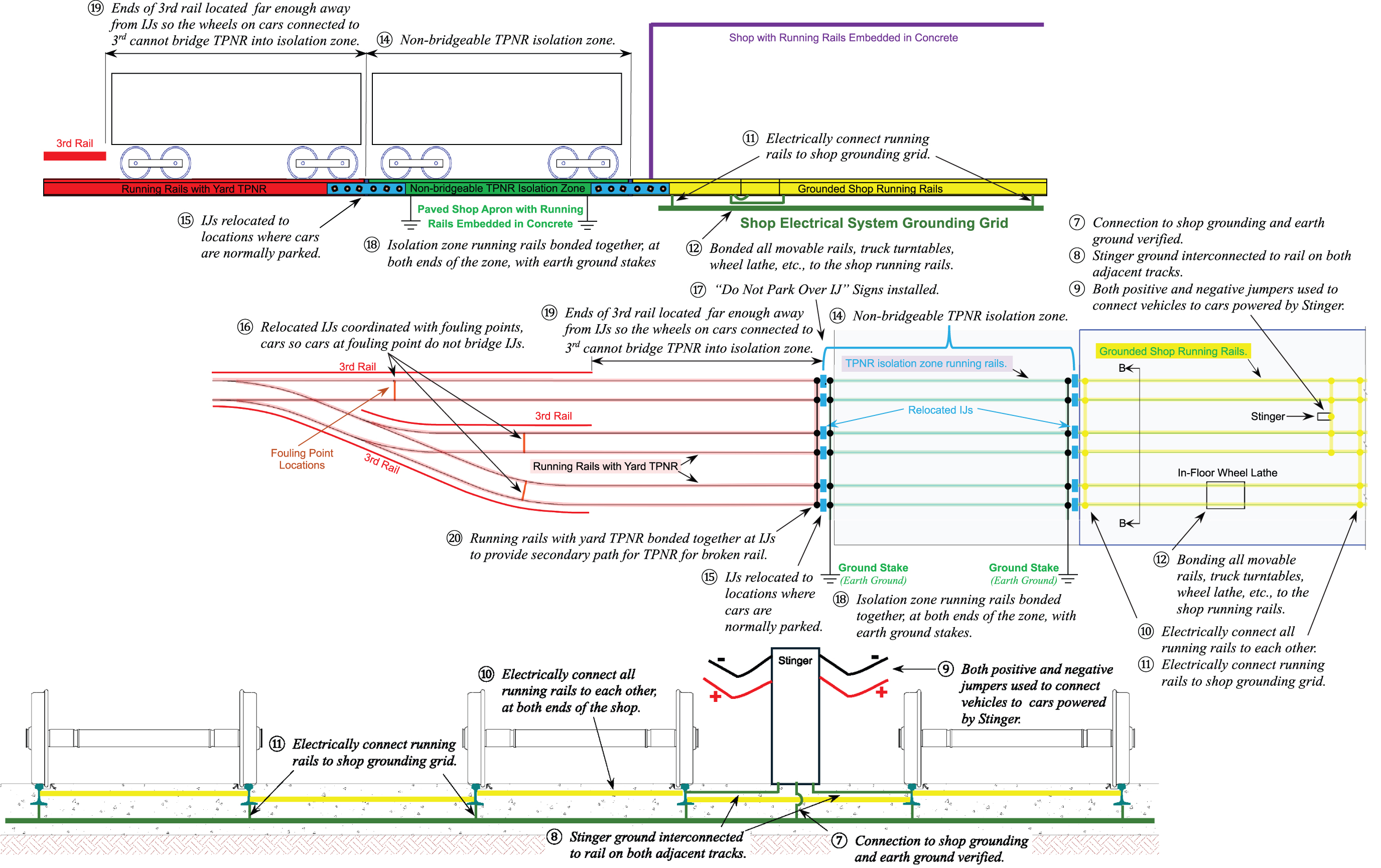
Long Description.
The illustration shows maintenace shop IJ arcing mitigations with labels as follows: 7. connection to shop grounding and earth ground verified. 8. Stinger ground interconnected to rail on both adjacent tracks. 9. Both positive and negative jumpers used to connect vehicles to cars powered by Stinger. 10. Electrically connect all running rails to each other. 11. Electrically connect running rails to shop grounding grid. 12. Bonded all movable rails, truck turntables. 14. Non-bridgeable TPNR isolation zone. 15. IJs relocated to locations where cars are normally parked. 16. Relocated IJs coordinated with fouling points, cars so cars at fouling point do not bridge IJs. 17. "Do Not Park Over I J" signs installed. 18. Isolation zone running rails bonded together, at both ends of the zone, with earth ground stakes. 19. Ends of third rail located far enough away from IJs so the wheels on cars connected to third cannot bridge TPNR into isolation zone.
-
- The distance between the ends of the third rail and IJs should not be less than the nonbridgeable gap distance used on the system.
- IJs intended for separating TPNR shop facilities should be coordinated with the grounding in the shop.
- Indications of IJ arcing were not noted during regular inspections because of a lack in understanding that IJ arcing is not normal or acceptable.
- Shop building grounding, grounding of rails within shop facilities, and TPNR must be coordinated.
- When making modifications to existing facilities or changes to the designs, ensure good electrical grounding and TPNR separation are maintained.
Case Study 5: Long-Lap Insulated Joints
Description
This electrified system has primarily passenger traffic, with some freight traffic, and third rail is used to distribute the traction power.
Issue
Indications of IJ arcing were found in certain locations. The cause of the arcing was initially determined to be the abrupt change in electrical potential at IJs with square rail ends as wheels passed over the IJs. The hypothesis was that the tapered rail ends provided by the long-lap IJs would provide a more gradual change in the electrical connection between the rail ends as wheels passed over IJs with tapered rail ends, thereby reducing or eliminating arcing (see Figure 28) (Davis, Pinney, and Alishio 2019a).
Results
Long-lap IJs did not resolve the arcing issues. After the replacement of IJs with square rail ends and with long-lap IJs, arcing still occurred. The only difference noted after the long-lap IJs were
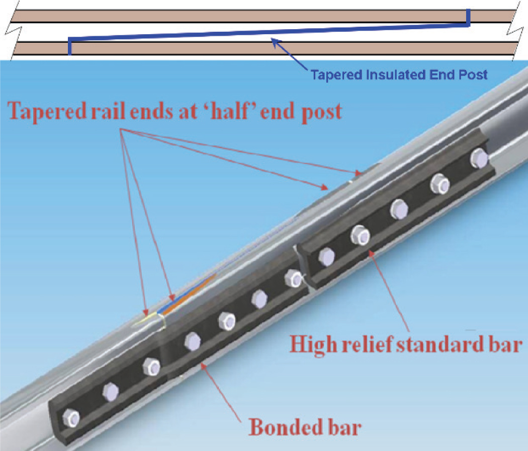
Source: Davis, Pinney, and Alishio 2019a (bottom illustration).
Long Description.
The parts marked on the photo include tapered insulated end post, tapered rail ends at the half end post, high relief standard bar, and bonded bar.
installed was the arcing damage was spread out over a longer area. This difference was attributed to wheels with slightly different wheel/rail contact bands that would generate arcing at different locations along the tapered end post (see Figure 29). Other mitigations were applied to address the issues at these locations (see Appendix B).
Lessons Learned
- Long-lap IJs do not mitigate IJ arcing.
- Long-lap IJs are more expensive than standard IJs; this is in addition to the installation cost.
- Long-lap and other enhanced design IJs have improved performance in heavy axle load environments.
- Matching the design of the rail profile through the lap area to the wheel profiles improves the longevity and performance of the long-lap IJ (Davis 2019b).
Case Study 6: Hi-Rail Switcher Arcing
Description
Wheel bearings were failing regularly on the guide wheels of hi-rail switchers used in a yard.
Issues
Standard rail maintenance equipment is designed primarily for the larger freight railroad market. Suppliers may not be familiar with the possible TPNR current that exists in the running rails on electrified railways. Some on-rail maintenance equipment may be designed to be electrically insulated when set on the track, so the vehicle does not interfere with railroad signaling systems; however, the typical insulation intended for nonelectrified railways [American Railway Engineering and Maintenance-of-Way Association, Manual for Railroad Engineering (AREMA MRE) 2024. Chapter 27, Part 2, Roadway Machines, Articles 2.3.5 and 2.7.5] may not be designed to withstand the TPNR electrical loads found on electrified railways.
Investigation
After multiple wheel bearing failures, the failed bearings were returned to the manufacturer for analysis. The bearing manufacturer indicated that the bearings were not failing due to manufacturing defects—the cause was identified as electrically induced bearing damage (EIBD) (see Appendix D). Further inspection of the vehicles experiencing repeated bearing failure found there was no insulation. Hi-rail switchers passing over IJs where TPNR was present in the running rails could provide a path through the wheel bearings to connect rails with differing potentials. Inspections of the guide wheels of the affected vehicles found indications of electrical sparking on the running surface of the guide wheels and the hydraulic system components used to raise
Source: Steven Abramopaulos, HNTB.
and lower the guide wheels. Field testing confirmed sparking as the hi-rail switchers passed over IJs. Sparking was also noted on open track at locations where there was a difference in electrical potential of the two adjacent running rails.
Other on-rail vehicles, including fixed-rail vehicles, were inspected, and similar arcing damage was found. Some of the equipment where arcing was found was specified as “insulated,” however, the insulation provided was designed for low-voltage train control track circuits, not for the high voltages/high currents normally found on electrified railways with TPNR.
The possibility of electrically insulating the guide wheels and bearings was investigated, and it was deemed too expensive to retrofit the vehicle. The chosen solution was to provide an alternate electrical path for the TPNR to protect the bearings, and other components, on the affected hi-rail switchers to prevent electrical arcing damage. Other vehicles with arcing damage were assessed on a case-by-case basis, and similar mitigations were implemented to prevent TPNR-induced damage to the vehicles.
Mitigations
Hi-rail switchers were equipped with wheel scrubbers and wiring to prevent bearing damage (see Figure 30).
Lessons Learned
- Typical hi-rail vehicles and roadway work equipment, including fixed-rail vehicles, might not be equipped to handle TPNR electrical loads when operating on electrified tracks.
- Wheel bearings and other components on hi-rail vehicles and roadway work equipment must be either electrically isolated or well bonded to prevent damage from TPNR.
- Insulation used for hi-rail vehicles and roadway work equipment must be sufficient to handle TPNR electrical loads.
- When procuring rail maintenance equipment to operate on electrified railways, specifications must be included for insulation and bonding around wheel bearings and other devices on the vehicle to prevent damage from TPNR.
- Any maintenance vehicle attachments or components that could come into contact with the running rails or earth ground (e.g., booms, outriggers, rail clamps) must be either well insulated or electrically bonded.
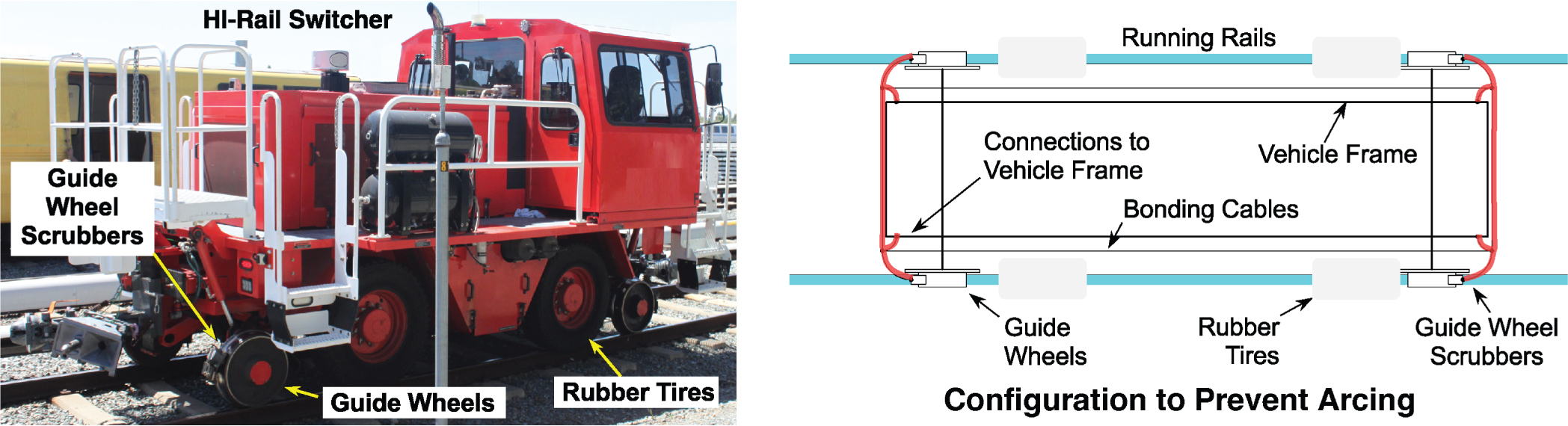
Long Description.
The photo shows a Hi-rail switcher with guide wheel scrubbers, guide wheels, and rubber tires. The illustration shows a configuration to prevent arcing. A vehicle frame with bonding cables and connections to the vehicle frame is on the running rails with parts labeled as guide wheels, rubber tires, and guide wheel scrubbers.
Case Study 7: Insulated Switch Rod Arcing Failures
Description
TPNR arcing occurred at switch rod insulation on an electrified railway.
Issues
The train control system and traction power systems were upgraded to facilitate reduced headways and longer train lengths. However, the upgrades to handle the increased train traffic and higher loads on the traction power system did not include upgrades to the TPNR system. After the upgrades were completed and the train traffic increased, arcing damage began to occur at the switch rod insulation. The transit had not experienced such failures in the past.
Investigation
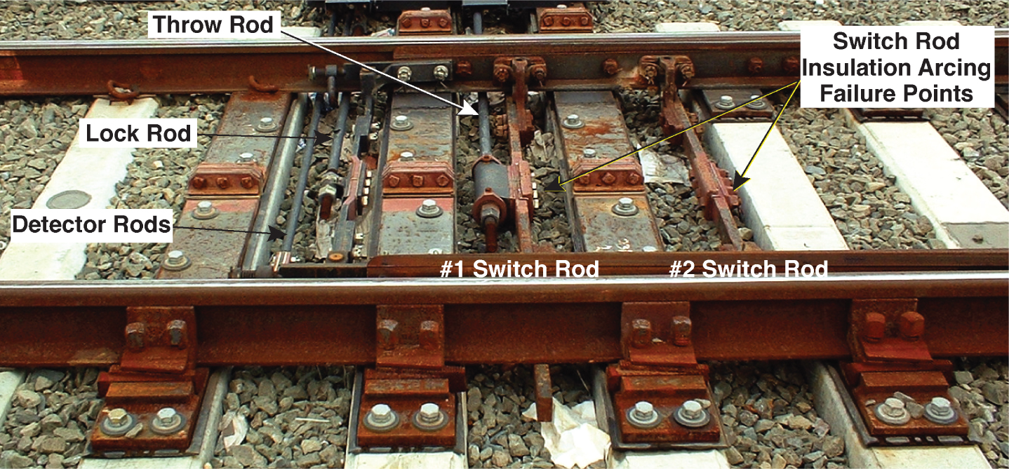
Initially, train control crews investigating problems with the train control track circuits discovered the failures and diagnosed the problem as failed switch rod insulation (see Figure 31). Track crews were dispatched to repair the insulation. The arcing continued at other locations, including reoccurrences at locations where insulation was recently replaced. In addition to the arcing at switch rods, the train control system experienced other damage, including melted signal and ground wires, blown fuses, and arc-damaged metal conduits, initially attributed to other unrelated electrical faults.
A team that included personnel from the areas of track, train control, and traction power was assigned to investigate the issues. Switch rods, with new and old insulation, were removed from the track. Signs of electrical arcing were found on rods that had not yet completely failed. Switch rods at select locations were completely replaced with brand new assemblies, and they also quickly failed.
Voltage measurements were taken across the switch rod insulation at a few locations. Those same voltages were applied to a new switch rod in a shop environment, and the insulation failed. Similar measurements were taken at other locations on the system with lower train headways and where traction power and train control upgrades were not performed. The voltage measurements at those locations were orders of magnitude less than those seen where the failures occurred.
Long Description.
The close-up shows the throw rod, lock rod, detector rods, and switch rod insulation arcing points. The switch rods are numbered 1 and 2.
Ultimately, the root cause of the arcing failures was attributed to the capacity of the TPNR system being insufficient to handle the increased electrical loads created by the increase in train traffic and the enhanced traction power supply system. Subsequently, it was decided that the switch rod insulation was inadequate for the imposed electrical loads.
Mitigations
Enhancements to the TPNR system were expected to take too long to implement. Reducing train service to reduce the load on the TPNR system was deemed unacceptable, and a short-term mitigation that could be implemented immediately was needed.
Initially, all the switch rod insulation was replaced in the affected area. Additional enhancements included applying insulation paint to metal surfaces and a thick coat of insulating silicon gasket paste to all mating surfaces prior to assembly. Nuts, bolts, and washers used in the insulating assemblies were also coated with dielectric (i.e., insulating) grease.
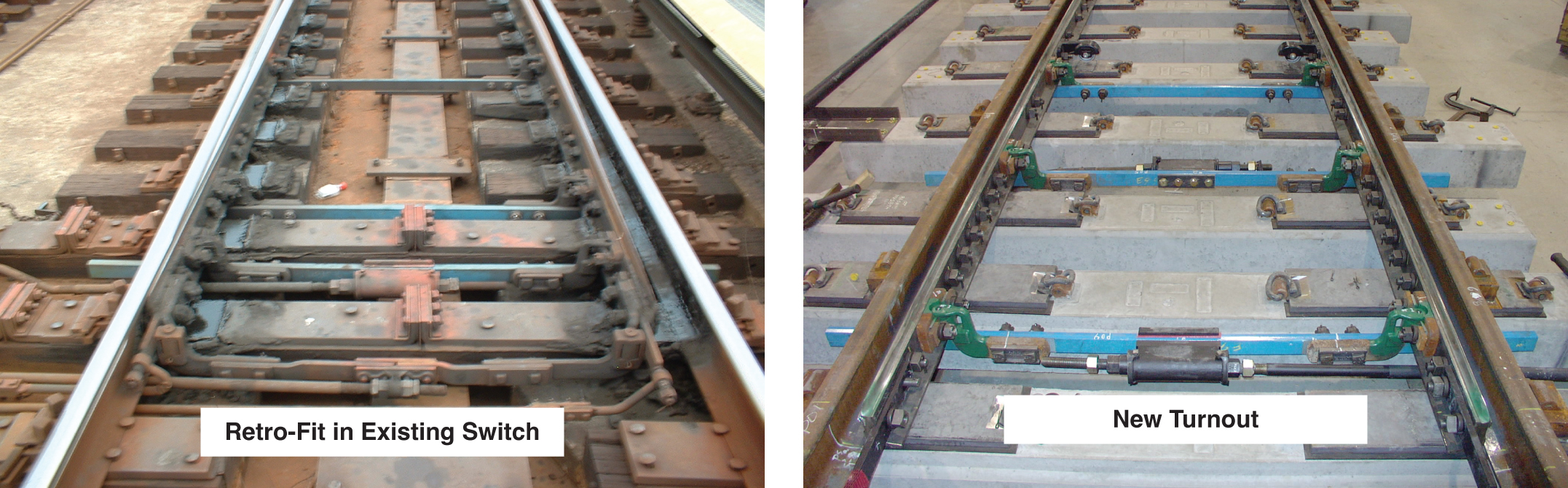
While the immediate mitigation was being implemented, other alternative materials that could provide improved insulation for the switch rods were researched. Research findings indicated that reinforced fiberglass material appeared to provide a direct replacement for the steel switch rod but would not require the replacement of the entire switch rod assembly. Concerns were raised about the strength of the material compared with that of the existing steel switch rods. Additional concerns about the deterioration of the proposed material were raised due to the materialʼs susceptibility to potential chemical attack (e.g., fuel spills) and sunlight.
Accelerated ultraviolet light deterioration testing and chemical resistance testing were performed on the material, and no deleterious effects were noted. The specified mechanical properties appeared to provide the strength needed, but concerns remained about possible failure modes. To address the failure mode concerns, it was determined that the highest mechanical load would likely be caused by a switch run through event. A test switch equipped with the reinforced fiberglass switch rods was run through multiple times. No adverse issues were observed during the test, other than the same types of damage that normally occurred with steel switch rods.
All the switch rods on the affected line were replaced with the reinforced fiberglass material. The replacement was intended to be a temporary mitigation until the TPNR system could be upgraded. Over time, the new material performed better than expected. The cost of the old insulation combined with the labor involved with replacement in the field indicated the old insulation was more expensive than replacement using the new material (see Figure 32).
Lessons Learned
- A multidisciplinary approach was required to identify root causes and determine the best solution for mitigating the issue.
- When loads increase on the traction power supply system, the loads on the TPNR system will also increase.
- When designing or upgrading traction power systems on electric railways, the same level of effort must be placed on the TPNR system as on the traction power supply system.
- Typical insulation designed for heavy-haul freight railroads with low-voltage train control systems may not be sufficient for the transit environment with TPNR.
- If the root cause of arcing problems cannot be immediately mitigated, other feasible mitigations must be found.
Case Study 8: Insulated Joint Arcing Through Track Components
Description
IJ arcing has been found on electrified railways where the following occur:
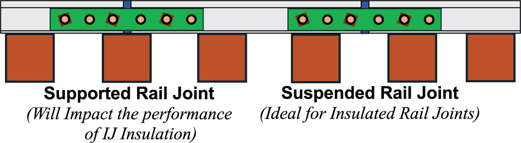
- IJ end posts are located on or near tie plates (supported rail joint) (see Figure 33).
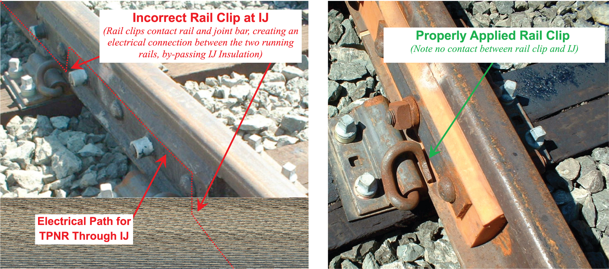
- IJs are shorted by improperly installed rail clips (see Figure 34).
- IJs are located where rail converges at switches, frogs, crossing diamonds, and other special trackwork, and adjacent rails are supported by the same tie plate (see Figure 35).
Long Description.
The illustration shows the supported rail joint with a support at each end and one more support in the middle. This will impact the performance of IJ insulation. The suspended rail joint has a support at each end. This is ideal for insulated rail joints.
Long Description.
The labels on one photo read as follows. Incorrect rail clip at IJ (Rail clips contact rail and joint bar, creating an electrical connection between the two running rails, bypassing IJ insulation) and electrical path for TPNR through IJ. The label on the second photo reads as follows: properly applied rail clip (note no contact between rail clip and IJ).

Long Description.
The photo on the left shows rails potentially connected through a tie plate (rail only insulated from the plate and by rail fasteners insulators). The photo on the right shows rails electrically connected through the tie plate (IJ bypassed).
Arcing occurs at the base of the rail under an IJ. The poor electrical connection typically results in intermittent arcing. At a minimum, the unplanned electrical path can interfere with the proper functioning of the train control track circuits (false occupancies), but damage can occur to the train control system from TPNR arcing.
Issues
Not all locations are suitable for the installation of IJs. When IJs are laid out, areas around frogs, switches, track crossings (diamonds), road crossings, guard rails, and restraining rails should be avoided wherever possible. Where IJs are needed at less-than-optimal locations, extra care is required to ensure that insulation afforded by the IJs is not bypassed by tie plates, other fasteners, or adjacent conductive materials, such as road crossing panels or embedded track concrete. When IJs are installed, the correct rail fasteners must be selected and properly installed to ensure the rail ends are not electrically connected, bypassing the IJ insulation and potentially creating arcing.
On one project, IJs were located close to the heel of a frog or switch, where the rails separated by the IJ were located on a tie plate shared by two adjacent running rails. The project had progressed to the point that the IJ could not be relocated without substantial delays. To mitigate the issue, the tie plate was replaced with a tie plate that provided electrical isolation between the metal tie plate and the two running rails (see left image in Figure 35). After the initial mitigation, the insulation on the single rail did work during testing. However, after the track was placed into regular service, the insulation failed, causing TPNR arcing between the base of the rail and the tie plate.
Mitigation
The metal plate that extended across both rails was replaced with a tie plate manufactured from insulated material, thereby resolving the arcing issue. The insulated plate continued to perform well over the long term without further failures (see Figure 36) (Shivy and Lai 2021).
Lessons Learned
- IJ locations must be carefully coordinated between track, train control, and traction power.
- Some locations are not suited for IJ installations. IJs should be located where they will provide the best performance.
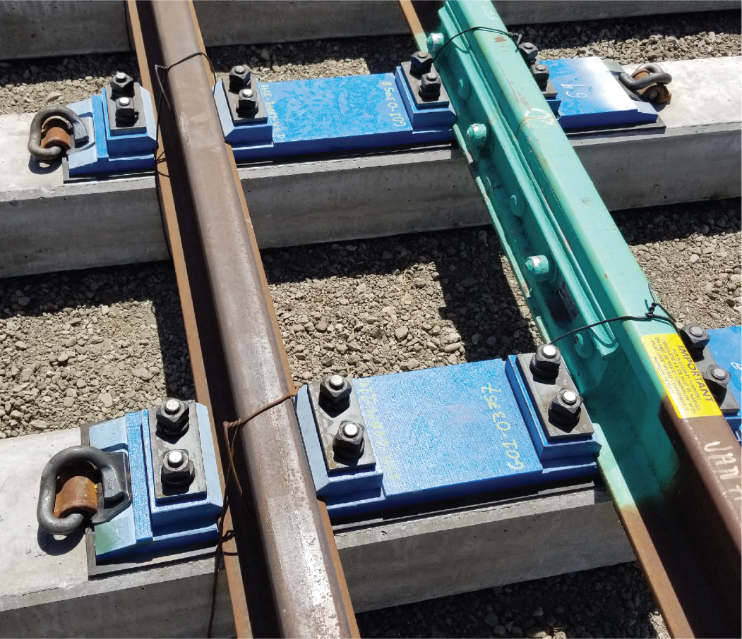
Source: Shivy and Lai 2021.
- For the best insulating performance, IJ end posts should not be installed on or close to ties or other supporting fasteners.
- The correct rail fasteners must be used at IJs to ensure the rail fasteners do not create electrical shorts through the IJs.
- Whenever possible, locate IJs where special (insulated) tie plates are not required.


