Investigation and Mitigation of Insulated Joint Electrical Failure: A Guide (2025)
Chapter: 3 Root Causes

CHAPTER 3
Root Causes
Traction Power Negative Return
The traction power for trains is distributed to the trains from the TPSS using either third (contact) rail or overhead catenary (OHC) along the track. The electrical circuit is completed through the train wheels, running rails, and cables; this circuit is called TPNR. TPNR is separated from earth ground through insulation in the track and cables. TPNR is not the same as earth ground, and electrical potential exists between the TPNR and earth ground (see Figure 1). The TPNR electrical circuit does not have unlimited capacity; if the capacity of the TPNR is exceeded, the overall traction power electrical system will perform poorly, with IJ arcing being one of the possible symptoms.
Insulated Joint Arcing
The IJ arcing phenomenon is unique to electrified railways. Although electrical train control circuits are used on most railroads, the differences in electrical potential are too small to cause arcing. On electrified railways, the running rails are used to complete the electrical circuit back to the TPSSs that provide the traction power for trains; on DC electrified railways this return circuit is called TPNR. The power used by a train must always return to the electrical TPSS providing the power, and it will always take the path of least resistance. If the path of least resistance is through the train as it passes over an IJ, and there is sufficient difference in the electrical potential difference between the rail ends joined by the IJ, then arcing can occur when the train wheel breaks the TPNR circuit path as it passes over the IJ.
Arcing at IJs is not normal—it indicates issues with the overall electrical system. A key word is “system,” and transit vehicles, traction power supply and return, train control, track, and train operations must be integrated and compatible with each other. While a deficient condition on a particular component of the system can lead to IJ arcing, it is critical that the design, maintenance, operations, and changes or modifications to the system be integrated. When IJ arcing is identified, seldom can one discipline resolve the issue. The various components, subsystems, and operations on an electrified railway are very interdependent; a seemingly innocuous change by one discipline can have major impacts on the other systems. The most successful mitigations to IJ arcing have been implemented through an interdisciplinary effort.
IJs are special rail splices that mechanically connect rail ends and electrically isolate the connected rails. The electrical separation provided by IJs in rails is required for the train control (signaling) systems that govern train operations and prevent conflicts in the movements of trains. IJs also are used to isolate TPNR in adjacent track segments. Different devices and strategies are

Long Description.
The illustration shows a traction power substation (TPSS) on the left and a transit vehicle on the right. The traction power substation is connected to the transit vehicle through an overhead connection marked traction power through the third rail or catenary. The circuit connects to the wheels and rail. The circuit is not grounded to earth, depicted by a no sign. A meter shows the potential between the earth ground and the circuit. A connection from the transit vehicle back to the traction power substation is marked traction power negative return (TPNR) through running rails (back to TPSS).
used to allow TPNR to bypass the IJs, while still providing electrical isolation between the rail ends required for the train control systems (see Figure 2).
IJs are not typically needed for the traction power system or for the track. IJs are primarily used to separate the track circuits used by the train control systems that govern train movements and prevent conflicts between trains. IJs and other components used in the track can create resistance in the TPNR circuit that can impede the flow of the TPNR current. These components in the TPNR system can create situations in which there are significant differences in electrical potential between adjacent tracks, opposite rails on the same track, and rail ends separated by IJs. If the TPNR system has sufficient capacity for the electrical loads imposed on the track, arcing will not occur. In many cases the conditions that cause IJ arcing are localized, and they affect only certain tracks, routes, or IJs, or occur only when trains are at certain locations or in particular propulsion modes.
IJ sparking and arcing are manifested by damage to the running surface to the rail head, ranging from pitting near the rail end to melted rail and burning damage to the rail and IJ assembly (see Figure 3). Appendix A, which features the Insulated Joint Rail End Inspection Guide, provides more details of IJ arcing and sparking as well as definitions for various levels of damage. The severity of the damage to the rail ends is related to the difference in electrical energy between the rail ends when the events occur. Arcing can be transient and may not occur with every train pass.
Arcing at IJs is not always caused by mechanical or insulation failures of the IJ. In many cases, arcing will reoccur after the IJ is replaced. IJ arcing is generally a symptom of TPNR system issues that allow significant differences in electrical potential between the two rail ends connected by the IJ. These issues do not indicate the TPNR system is defective or to blame for IJ arcing; they only indicate the loads imposed on the TPNR system exceed its capabilities in its current condition and configuration. If the underlying causes that generate excessive differences in electrical potentials in the TPNR system remain, then IJ arcing will continue.
Arcing does not occur spontaneously across the rail ends separated by IJs; the arcing is initiated by passing train wheels. For arcing to occur, there must be a difference in electrical potential at the rail ends separated by the IJs. Small differences in potential are normal at IJs. As train wheels pass over an IJ, both rail ends are connected; however, as the wheel proceeds over the IJ end post, contact is lost on the trailing rail end. If there is sufficient electrical energy, sparking or arcing will occur. The level of the damage to the rail (and train wheels) is proportional to the differences in the electrical energy when the arcing occurs.
Where destructive levels of arcing occur, the electrical energy causing the damage can be tens of volts, hundreds of amps, or more. IJ arcing does not necessarily occur when every train passes

Long Description.
The exploded view shows the insulating end post with a set of six fastener assembly rails through joint bars and a reinforced epoxy insulating layer to the running rails with insulating bushings between them. The section through bolt shows running rail at the top, followed by the reinforced epoxy insulating layer and joint bars with insulating bushings at the bottom. The fastener assembly is horizontal from right to left. The photo shows a section with two running rails joined together by a joint bar with an insulating end post between them. The joint bar has a set of six fastener assemblies with a reinforced epoxy insulating layer between the joint bar and rails.

Sources: Steven Abramopaulos, HNTB (lower right); all others courtesy of MxV Rail.
Long Description.
The first two photos at the top show the indications of light sparking at the left edge of the gap between the rails, with the direction of traffic when sparking occurred to the right. The last two photos show indications of destructive arcing in the gap between the rails. The direction of traffic when the arcing occurred is to the right in the third photo (bottom left). The text in the fourth photo (bottom right) reads, direction of traffic not always discernable in extreme events.
over an IJ. Arcing might occur only sporadically. Sometimes transient conditions, for example, additional trains in the area, multiple trains simultaneously accelerating, or special events that cause unusual train densities, can result in atypical increased loads on the TPNR system. More detailed explanations of the various systems, subsystems, and components used on transits with electrified railways are provided in Appendix D.
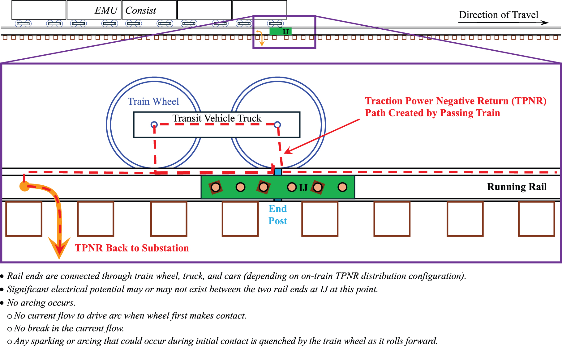
Figures 4 through 8 provide an example sequence that can result in IJ arcing on an electric multiple unit (EMU) consist. The EMUs in this example consist have onboard TPNR distribution

Long Description.
The Electric Multiple Unit (EMU) consist is just left to an insulated rail joint (IJ) with the direction of travel to the right. An enlarged view shows the wheels below a transit vehicle truck, just left of an insulated end post with an insulated rail joint immediately below the post. A curved down arrow from a point on the left is labeled TPNR return cables to the traction power substation (TPSS). The text at the bottom reads as follows. No arcing occurs at this point. Significant electrical potential may or may not exist between the two rail ends at IJ at this point.
Long Description.
The lead axle of the Electric Multiple Unit (EMU) consist is above an insulated rail joint (IJ) with the direction of travel to the right. An enlarged view shows the wheels below a transit vehicle truck, just above the insulated end post with an insulated rail joint just below the post. The current passes through the curved down arrow on the left, labeled TPNR, back to the substation after passing through the traction power negative return (TPNR) path created by the passing train. The text at the bottom reads as follows. Rail ends are connected through the train wheel, truck (and cars depending on the on-train TPNR distribution configuration). Significant electrical potential may or may not exist between the two rail ends at IJ at this point. No arcing occurs, no current flow to drive arc when wheel first makes contact, no break in the current flow, and any sparking or arcing that could occur during initial contact is quenched by the train wheel as it rolls forward.

Long Description.
The insulated rail joint (IJ) is between the two cars of the Electric Multiple Unit (EMU) consist with the direction of travel to the right. An enlarged view shows the insulated end post between the wheels of two cars with an insulated rail joint just below the post. The circuit designed on board the TPNR electrical path joins the two cars, and the current passes through the curved down arrow on the left, labeled TPNR, back to the substation. The text at the bottom reads as follows. The two rails at the IJ are connected through train wheels, trucks, and through car. (depending upon the on-train TPNR distribution configuration.) The TPNR electrical path is designed and engineered, and not an unintended path for the TPNR. Significant electrical potential may or may not exist between the two rail ends at IJ at this point. No current flow between rail ends at IJ. No IJ arcing occurs.

Sources: Steven Abramopaulos, HNTB (top photo), and MxV Rail (bottom photo).
Long Description.
The insulated rail joint (IJ) is between the two cars of the Electric Multiple Unit (EMU) consist with the direction of travel to the right. An enlarged view shows the real wheel of the first car passing over the post with possible sparking depicted. The current passes through the TPNR path created by the passing train. The text at the bottom reads as follows. The connection of the rail ends is broken as the last axle of the car in the middle of the consist passes over IJ (depending on on-train TPNR distribution configuration). No arcing should occur. Sparking and arcing are not normal conditions. Sustained arcing between rail ends is not common. If it does occur, the arc is extinguished by the next passing wheel. Potential difference and magnitude of the amps depends on (1) the number of cars in this consist between the IJ and the substation supplying the power to the train, (2) the number of other trains between the IJ and the substation supplying the power, (3) propulsion modes of this (and other trains) between the IJ and the substation supplying the power---Accelerating trains draw more power, and trains in regenerative braking mode place higher loads on the system---and (4) the electrical resistance in alternate TPNR pathways (back to the substation providing the traction power, See Appendix D)---cross-bonds, impedance bonds, cable connections, and adjacent tracks and running rails. A set of two photos depicts the light and heavy sparking.

Long Description.
The rear wheel of the last car of the Electric Multiple Unit (EMU) consist passes over the insulated rail joint (IJ) with the direction of travel to the right. An enlarged view shows the rear wheel of the first car passing over the post with possible sparking depicted. The current passes through the TPNR path created by the passing train. The four points listed are as follows. 1. No arcing, normal condition, small difference in potential. 2. Sparking, low potential difference. 3. Light destructive arcing, large potential difference, and no arcing between rail ends. 4. Heavy destructive arcing, large potential difference, and arcing between rail ends. The text at the bottom reads as follows. Connection of rail ends broken as last axle of the last car of the consist passes over IJ. No arcing should occur. Sparking and arcing are not normal conditions. Where arcing occurs, the level of the arcing is dependent on the difference in electrical potential between the rail ends as the wheel passes and the magnitude of the power flow (amp) when the connection is broken. Potential difference and magnitude of the amps depends on the number of cars of this consist between the IJ and the substation supplying the power to the train, the number of other trains between the IJ and the substation supplying the power, the propulsion modes of this (and other trains) between the IJ and the substation supplying the power (accelerating trains draw more power and trains in regenerative braking mode place higher loads on system), and the electrical resistance in alternate TPNR pathways (back to the substation providing the traction power, See Appendix D): cross-bonds, impedance bonds, cable connections, adjacent tracks and running rails.
through each car (wheels, axles, and trucks electrically connected). Figure 9 provides examples of the levels of arcing that might occur when there is excessive electrical potential at the rail ends of IJs.
Traction Power Negative Return Imbalances
There should not be significant electrical imbalances in the TPNR system between adjacent tracks, between opposite rails, or between the two rail ends at IJs. If IJ arcing occurs and the cable connections and IJs are found to be in good condition, then the source of TPNR electrical potential imbalances should be investigated and a strategy developed to mitigate the imbalances. These mitigations typically involve (1) enhancing the TPNR system (decreasing resistance) by adding additional bonding cables at existing bonding locations, new or additional bonding, and so on; (2) enhancing the train control system by adding new impedance bonds, increasing the ratings of existing impedance bonds, and so forth; or (3) reducing the electrical loads. However, these changes need to be carefully coordinated with the train control and track designs and may not always be possible without significant (and costly) modifications.

Sources: Steven Abramopaulos, HNTB (“Light Sparking,” left; “Medium Sparking,” left; and “Heavy Destructive Arcing,” all); all others courtesy of MxV Rail.
Long Description.
The photos depict the direction of movement to the right and the trailing rail end with different types of arcing as follows:
1. Light sparking. Random pitting near the rail end. Each spot on the rail represents a different wheel pass.
2. Medium sparking. Expanded pitting near the rail end. Deeper pitting. Longer slash wider area of damage.
3. Heavy sparking. Random pitting near the rail end. Increased pitting depth. Larger area of damage.
4. Light destructive arcing. A distinct spot of melted metal, surrounded by darkened burn marks.
5. Heavy destructive arcing. Both rail ends melted. Rail end metal loss. Burn marks on rail, end post, joint bars, and insulation. Rail ends are electrically connected. The direction of movement may not be evident.
While imbalances in the TPNR system can lead to IJ arcing, the design of the TPNR system is not necessarily the root cause. Imbalances in the TPNR system and IJ arcing can occur when the loads imposed on the TPNR system exceed its capabilities in its current condition and configuration. When IJ arcing is found, the root causes that generate the TPNR imbalances must be understood to determine the best mitigation.
Poor Electrical Connections
A common cause of IJ arcing is poor or loose electrical connections. There can be many cables and connections in the track between trains drawing power and the TPSS providing power to that train. If a cable connection is loose, corroded, broken, or missing, it can create high resistances that impede the flow of the TPNR. In some cases, when IJ arcing occurs, inspecting these connections can identify the offending cables/connection. Checking TPNR cables and connections as well as the condition of the IJ where arcing is occurring should be one of the first steps when IJ arcing is discovered. Loose connections can be quickly identified and easily repaired (see Figure 10).
Insulated Joints
An IJ is a discontinuity in the track and inherently a weak link that requires more maintenance than other track. Loads and impacts from passing trains and daily temperature cycles cause IJs to deteriorate more quickly than the adjacent track. There are many conditions that can reduce the performance of the IJ insulation or reduce the ability of IJs to resist arcing. If IJ arcing is found, the IJs, along with the cable connections, should be the first items inspected. Any conditions on the IJ that may degrade its performance should first be mitigated. Appendix A, which features the Insulated Joint Rail End Inspection Guide, details how to identify IJ arcing and common IJ issues that can reduce the ability of IJs to resist arcing.
On existing systems, IJ arcing can occur after maintenance or modifications are performed on IJs. Any changes made to IJ locations and layouts should be carefully coordinated and integrated across all disciplines. While static testing may be performed on new IJs, it may not emulate all the possible electrical loads imposed under traffic. When maintenance is performed, the IJs should be monitored for poor performance. Care must be taken to return the systems to their original configuration, or if changes are planned, the changes should be coordinated.

Photos courtesy of MxV Rail.
Long Description.
Both images show close-ups of poor bond cable electrical connections.
Train Operations and Vehicles
Wayside infrastructure is not independent from train operations and the vehicles. Changes in train traffic, higher horsepower trains, increased acceleration rates, changes to the locations where trains accelerate, heavier transit vehicles, longer trains, increased traffic density, the introduction of regenerative train braking, and more, can have significant impacts on the wayside infrastructure.
Traction power systems do not provide unlimited power. The design of the traction power system is based on power load assumptions made when the system was designed. These design assumptions are not generated in a vacuum by the traction power engineers; the possible loads imposed on the traction power system must be provided to the traction power design team so the system can be designed for those loads. Items that affect the assumptions used for traction power system design include power needed for each car and train, the number of trains to be operated, train spacing, track alignment and grades, locations of stations, locations of TPSSs, and more.
The design of the traction power system can limit train operations; if those operating limits are exceeded, performance issues, including damage to the revenue vehicles and traction power system, can arise. A change in vehicles or operations can impact the traction power system, including the TPNR. When new operating practices or new vehicles are introduced, the impacts of those changes must be matched to the capabilities of the other related systems, and possible consequences must be assessed. Any possible repercussions must be mitigated before implementing any changes to prevent problems in the overall system performance.
After any changes are implemented to a transit system, or to new systems, the entire system should be carefully monitored so any unusual conditions can be quickly identified. If IJ arcing is discovered, the issue should be quickly escalated and the root causes identified and mitigated.
Increased Traction Power Loads
Power systems are very expensive, and their design effort is very complex. Their cost is based heavily on the power they need to supply the trains. Designing unlimited capability for the traction power system is not economically feasible. Those who design the traction power systems need to rely on data (provided by others) related to the power needs of the trains, train scheduling, how many trains will be in each area at the same time, track curvature, grades, train speeds, station locations, and more. Increased load demands on the traction power system can increase the costs of the traction power system by tens or hundreds of millions of dollars. The traction power system designs are made more complex if there are limitations on where the TPSS can be located.
If loads increase, additional TPSSs may be required. Finding space for ancillary buildings, such as TPSSs, can be challenging in urban environments, where the cost and competition for property is high. Further, the locations available for TPSSs can be limited by the impacts to neighbors resistant to the location of industrial buildings, such as a TPSS, in a residential area.
Increasing train length (more cars drawing power), increasing train density (more trains in each area), increasing track grade (increased loads on grades), station locations (more power required to accelerate from station stops), and trains accelerating up steep grades are just a few of the items that can increase the demands on (and costs of) traction power systems. The demands on the system can be further increased when service recovery scenarios are considered, for example, with service delays or special events where trains are temporarily bunched up in a short area and thus create localized increases in traction power loads.
On new systems, the capabilities of the system are typically driven by available funding, and hard decisions must be made to minimize the costs of the traction power system. It is not unusual for the design to be based on minimal initial service. The concept is to increase the traction power
system capabilities later, before future service increases. Increased demands on the traction power supply system will also place higher loads on the TPNR system, which must be accounted for when enhancements are made to the traction power supply systems. If the TPNR system capacity is insufficient to support increased loads, negative impacts like IJ arcing may result.
Assumed Traction Power Negative Return Track Resistance
Many electrified railways do not design the TPNR system in detail. It is not uncommon for a general assumed resistance per lineal foot of track or right-of-way to be used. Although the positive side of the traction power system, including the capacity of the TPNR cables between the track and TPSSs, may be modeled and designed in detail, the same level of engineering is not always applied to the TPNR network in the track.
Most traction power system design drawings detail only the power supply (TPSS, TPSSs to track, and third rail/OHC), showing only the connection location and the number of cables returning TPNR from the track to the TPSS, relying on other disciplines to detail the TPNR network in the track. The details of how the TPNR loads are transmitted through the track are not always engineered in detail. How the current flows through the TPNR system can be just as complex as the positive side of the system. What can happen to the TPNR system under load, throughout the track structure and train control equipment (including at IJs) should be engineered in detail. Simple assumptions of track resistance may lead to performance issues.
The lack of detailed design on the TPNR system can lead to IJ arcing. On many systems, the design assumptions were conservative enough for historical loadings; however, assumptions on the TPNR system capabilities may not work when there are increased demands on the traction power and TPNR systems. Some transits preclude detailed engineering or modeling of the TPNR system, requiring traction power engineers to use given values. If the power loads increase, the demands on the TPNR system will also increase. The design of the TPNR system must be evaluated to ensure it can handle the increased loads and prevent IJ arcing and other negative impacts.
Some of the specialized design software packages for traction power design only use a simplified TPNR system in their models, using assumed values. Other software has the capability to model the TPNR system as the complex system that it is, allowing for viewing of each component (rail segments, each cable, connection, etc.) as a separate “node” on a micro level, so the load demands and performance of the TPNR system can be assessed and the needed capabilities engineered into the designs. Modeling and designing the TPNR system can prevent IJ arcing and be used to determine root causes of IJ arcing on existing systems. TPNR modeling is discussed in more detail in Appendix D. Further recommended research that will support improved modeling is detailed in Appendix F.
Design Integration
The significance of integrating design cannot be overemphasized. The increasing complexity of transits with electrified railways requires additional effort to ensure the overall system works properly. Minor changes made by one discipline can have major impacts on other systems. Overly simple single-discipline solutions to a problem can have serious impacts on another discipline. Without adequate integration of the designs, the overall system may not perform well.
Because of the complexity of each discipline, it is not always possible for those who design any one system to fully understand the other disciplines. A seemingly elegant and cost-effective solution for an issue that solves a problem for one or two disciplines can create issues not easily
resolved for another discipline. TPNR is a complex system that includes transit vehicles, train control systems, track, traction power systems, and train operations. Arbitrary requirements of one discipline or a lack of coordination between the designs of these systems can lead to poor performance, including arcing at IJs.
Situations where design integration was not adequately performed may arise. Recognizing how an issue occurs is important in avoiding a future recurrence of the issue. Many times, it becomes a leadership issue to address design conflicts; human nature and stubbornness can come into play. The various groups and disciplines involved must work together toward the best solution. Narrow, department-centric attitudes will not resolve issues or generate the best overall solution. The most elegant solutions to a design conflict may not be timely or affordable. A less-than-perfect solution that will mitigate the issue and can be quickly implemented to create resolution might be the best path forward, even if that solution is the least desirable for a single discipline. Situations may arise where the root cause of the problem cannot be resolved, so an alternative solution must be found.
For example, on one transit, the track designs for turnouts were standardized, including the layout of IJs, thereby reducing costs and simplifying materials management and field installations. However, the IJ layout was not compatible with the train control and TPNR designs, and it created issues unrelated to the track design. In another scenario, if the root cause of IJ arcing is found to be the design of a new fleet of transit vehicle, and the required modification to those vehicles is not feasible, replacement of the current vehicles is simply not an option. In this case, other solutions must be found to mitigate the issue. Affordable and time-effective solutions can always be found through design integration and cooperation between the various disciplines involved.
IJs are required for train control systems that use track circuits. The installation locations and layouts are primarily driven by the proper functioning of the train control system, based on the track layouts and transit vehicle design. IJs impact the optimal performance of the track, the traction power systems (including TPNR), the transit vehicles, and operations. However, IJs are a necessity and must be accommodated by all disciplines. Design compromises must be made to ensure that the various subsystems in the complex electrified railway environment can work together efficiently.
Design integration can prevent most IJ arcing and other issues. When IJ arcing is discovered on an existing system, and the issue is not easily resolved by repairs to obvious deficiencies (IJs, loose cables, etc.), the solution can be implemented only through an integrated multidisciplinary approach.
It is critical that any design changes made by a single discipline be coordinated and integrated. Seemingly innocuous changes made by a single discipline may impact the performance of other disciplines and can lead to the poor performance of the overall system. Modifications, such as shifting the location of an IJ by a few feet, changing the TPNR bonding layout, or changes to the on-train power or TPNR distribution, running additional trains, and more, can have serious effects on the performance, and in some cases the safety, of the overall system.
Alternating Current Traction Motors
IJ arcing can be found on electrified railways using DC traction motors, a mix of AC and DC traction motors, and those only using AC traction motors. AC traction motors do not cause IJ arcing. The use of AC traction motors on a new system or the introduction of AC traction motors on an existing system will not necessarily cause IJ arcing. IJ arcing is more related to the design and capacity of the TPNR systems based on the imposed loads. Systems that only use AC traction motors do not necessarily have IJ arcing issues, therefore, no correlation can be made between the use of AC traction motors and IJ arcing.
During the development of this guide, a special effort was made to investigate how the use of AC traction motors may contribute to IJ arcing. AC traction motors have significant advantages over DC traction motors. In the past, DC traction motors were used on electrified railways, whether the power was distributed as DC or AC. Recent technologies allow the application of more efficient AC traction motors in the railroad environment. More discussion on AC traction motors is provided in Appendix D, System Technical Descriptions.
At a high level, it may seem inefficient to take AC electricity from the power grid, convert it to DC for distribution along the track (OHC or third rail), then reconvert the DC to AC on the trains. There are limitations to AC distribution along the trackway and the cost of retrofitting an existing DC distribution system to an AC system is very cost prohibitive. On an existing system, replacing the traction power distribution network, in addition to replacing or retrofitting the trains, would not only be a massive capital investment, but it could also require a complete shutdown of the system, perhaps for many years, while the changes are implemented.
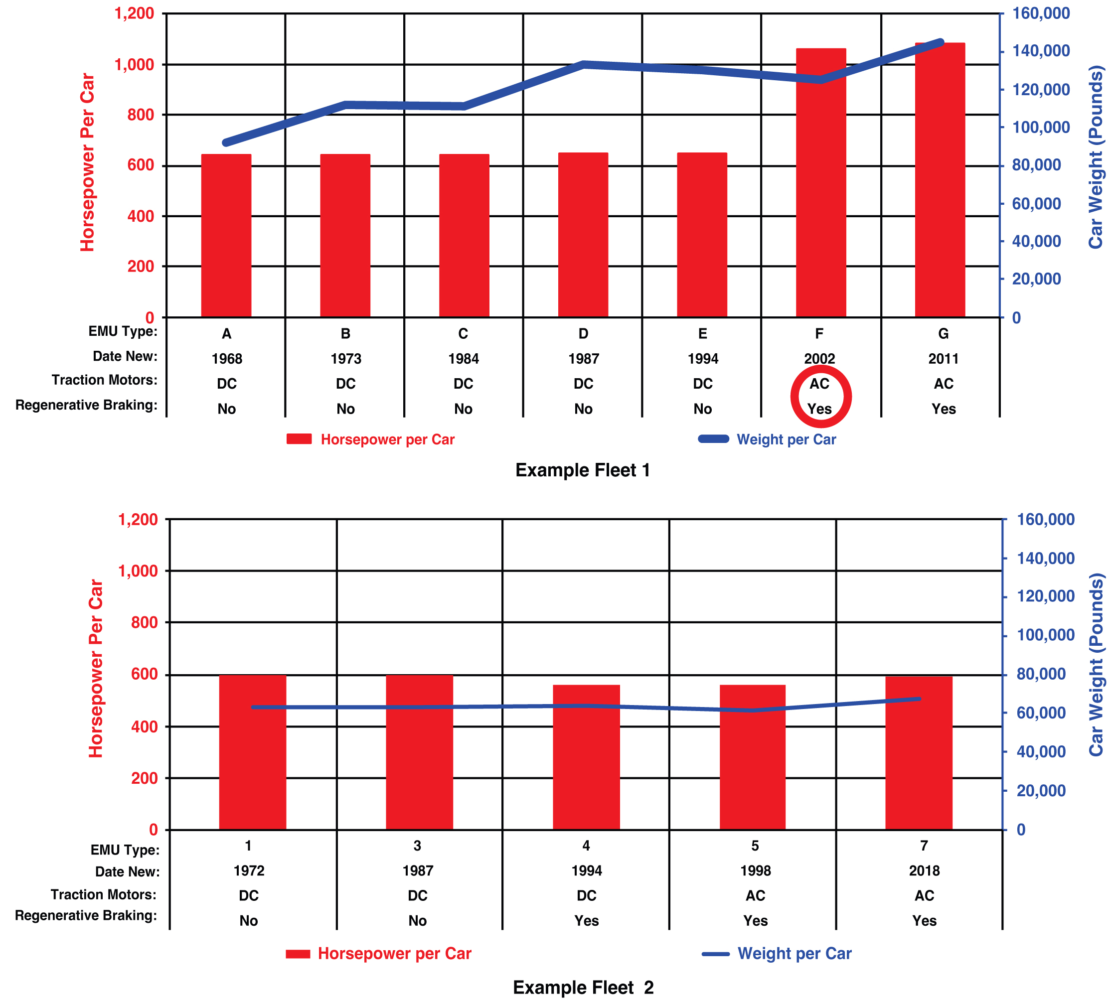
Figure 11 shows an example history of EMU vehicle specifications for two different systems. AC traction motors and regenerative braking, along with a 66 percent increase in horsepower per vehicle, were introduced with Type-F cars in example fleet 1. Over time, the car weights gradually increased by nearly 57 percent. Example fleet 2 also introduced AC traction motors and regenerative braking, but the horsepower per vehicle and the vehicle weight remained nearly the same. If IJ arcing was noted with the introduction of the AC traction motors, then the AC traction motors cannot be singled out as the cause of IJ arcing when other significant changes are also being made. The cause of IJ arcing should not be attributed to a single factor without investigating all possible contributing factors.
When investigating IJ arcing, the timing of the changes should be compared to when IJ arcing was noted. Changes can be phased in gradually with new vehicles introduced to revenue service over a period of years as they are produced and other vehicles retired as the new vehicles are introduced; changes to the infrastructure may take months or years to complete; and increases in operations (more trains/longer consists) may be phased in over time. Any one change could increase power demands on the overall traction power system, but only the combination of multiple changes creates the conditions needed for IJ arcing to occur.
The root causes of IJ arcing should not simply be attributed to a single cause, such as the use of AC traction motors. When IJ arcing is found, vehicles, operations, and changes to the infrastructure should be considered as possible causes behind the arcing, including the following:
- Increased train acceleration rates
- Locations where train accelerations occur
- Number of cars in train consists
- Maximum operating speeds
- Reduced train headways
- Number of trains being operated
- Introduction of regenerative train braking
- Changes to IJ locations and layouts
- Changes to bonding
- Changes to the traction power system, including the following:
- Higher capacity TPSSs
- Increasing the number of TPSSs
- Reducing the distances between TPSSs
- Increasing the capacity of cables between the TPSS and wayside distribution systems
- Reducing the resistance of the third rail/OHC
When the traction power system is enhanced to address increased power demands, similar enhancements to the TPNR system must also be considered to prevent performance issues.
Long Description.
The top graph depicts Example Fleet 1. The vertical axis on the left shows horsepower per car ranges from 0 to 1,000 in increments of 200. The vertical axis on the right shows car weight (in pounds) ranges from 0 to 140,000 in increments of 20,000. The horizontal axis lists seven categories with data as follows:
1. EMU type, A. Date new, 1968. Traction motors, DC. Regenerative braking, no. Horsepower per car, 640. Car weight: 90,000 pounds.
2. EMU type, B. Date new, 1973. Traction motors, DC. Regenerative braking, no. Horsepower per car, 640. Car weight: 110,000 pounds.
3. EMU type, C. Date new, 1984. Traction motors, DC. Regenerative braking, no. Horsepower per car, 640. Car weight: 110,000 pounds.
4. EMU type, D. Date new, 1987. Traction motors, DC. Regenerative braking, no. Horsepower per car, 640. Car weight: 113,500 pounds.
5. EMU type, E. Date new, 1994. Traction motors, DC. Regenerative braking, no. Horsepower per car, 640. Car weight: 113,400 pounds.
6. EMU type, F. Date new, 2002. Traction motors, AC. Regenerative braking, yes. Horsepower per car, 1,050. Car weight: 120,000 pounds.
7. EMU type, G. Date new, 2011. Traction motors, AC. Regenerative braking, yes. Horsepower per car, 1,080. Car weight: 140,000 pounds.
The bottom graph depicts Example Fleet 2. The vertical axis on the left shows horsepower per car ranges from 0 to 1,200 in increments of 200. The vertical axis on the right shows car weight (in pounds) ranges from 0 to 160,000 in increments of 20,000. The horizontal axis lists five categories with data as follows:
1. EMU type, 1. Date new, 1972. Traction motors, DC. Regenerative braking, no. Horsepower per car, 600. Car weight: 60,000 pounds.
2. EMU type, 3. Date new, 1987. Traction motors, DC. Regenerative braking, no. Horsepower per car, 600. Car weight: 60,000 pounds.
3. EMU type, 4. Date new, 1994. Traction motors, DC. Regenerative braking, no. Horsepower per car, 570. Car weight: 60,000 pounds.
4. EMU type, 5. Date new, 1998. Traction motors, AC. Regenerative braking, yes. Horsepower per car, 570. Car weight: 60,000 pounds.
5. EMU type, 7. Date new, 2018. Traction motors, AC. Regenerative braking, yes. Horsepower per car, 600. Car weight: 60,000 pounds.


