Investigation and Mitigation of Insulated Joint Electrical Failure: A Guide (2025)
Chapter: Appendix C: Documentation and Field Work

APPENDIX C
Documentation and Field Work
Purpose
Another component of TRB TCRP Project D-20, “Investigation and Mitigation of Insulated Joint Electrical Failure,” was to determine the best mitigation of insulated joint (IJ) electrical failures. However, there is not always a simple or single solution to mitigate IJ arcing. This appendix details some additional efforts that may be required to resolve IJ arcing.
Background
IJs are special rail splices that mechanically connect rail ends and electrically isolate the connected rails. The electrical separation in rails provided by IJs is required for the train control (signaling) systems that govern train operations and prevent conflicts in the movements of trains. IJs are also used to isolate traction power negative return (TPNR) in adjacent track segments. Different devices and strategies used to allow TPNR to bypass the IJs should still provide electrical isolation between the rail ends required for the train control systems.
Electrified railways experiencing the IJ arcing covered in this study distribute the electric traction power as direct current (DC) using either contact (third) rail or overhead contact wire/catenary (OHC) systems. Some properties have trains that use alternating-current (AC) traction motors. On these trains, the DC power collected from the traction power system is converted to AC power onboard the trains to power the AC traction motors that drive the trains. Any power drawn by trains from a particular traction power substation (TPSS) must be returned to that same TPSS. Traction power is returned to TPSSs primarily using the running rails of the tracks, in addition to cables and bonding (cable connections). This return circuit is called TPNR.
TPNR is not the same as an electrical earth ground; it is a separate electrical circuit. Electrical potential difference exists between the TPNR and earth, and the difference in electrical energy can be significant at tens of volts and thousands of amps or more. TPNR systems are electrically isolated from earth ground to control stray currents that can damage the rail and adjacent electrically conductive infrastructure.
After the introduction of new vehicle fleets with AC traction motors, some DC electric railways noted IJ failures due to electrical arcing. Electrical arcing is not normal in electrified railways and is indicative of other underlying issues. Typically, IJ arcing and associated rail damage are caused by symptoms of other issues that create excessive TPNR electrical potential differences at the rails joined by the IJs, by a mechanical or insulation failure in the IJ assemblies. Where arcing occurs at IJs, the running rails, IJs, train control systems, and equipment on trains can be damaged, and the impacts are further compounded by delays to train operations caused by the arcing damage. While IJ arcing can occur on electrified railways with AC power distribution
systems, the mitigation efforts are very different from those for DC systems and are outside the scope of this work.
Documentation Collection
When simple solutions to resolve IJ arcing issues cannot be found, a more extensive document review may be required. This review can be a challenging effort if the needed records are not readily available. Where records are not available, only the best effort can be made, and the records that are easily obtainable are the ones that are used. In some cases, older historical records may no longer be relevant, as the site conditions have changed since the original construction, or the available maintenance records may predate infrastructure changes.
The document collection should not be limited to narrow disciplines and should include track, train control, traction power, vehicle maintenance, and operations. Records and drawings that can be useful in investigating the root causes of IJ arcing can include the following:
- Design drawings
- Construction change orders
- Construction noncompliance reports
- Construction test reports
- As-built drawings
- Track charts
- Maintenance manuals
- Wayside infrastructure maintenance records (track, train control, and traction power)
- Vehicle maintenance records
- Control center logs
- Train control system logs
The document collection effort should be limited only by the severity and complexity of the problem. A layered approach can be taken when resources are available for the document collection effort, beginning with the documents that initially appear to be the most relevant. If the issues cannot be determined, a more extensive effort may be required, beginning with those records that are determined to be the most useful and take the least time and effort to retrieve.
As-Built Drawings
Record drawings (as-builts) are useful in determining potential contributing factors to IJ arcing. However, as-builts cannot necessarily be taken to accurately reflect what is truly out in the field. Changes made during construction or preoperational testing may not always be included in the as-builts.
Construction or rehabilitation of electrified railways can take many years and may be performed by multiple contractors or subcontractors. It is not unusual for contractors to complete their work and submit accurate as-builts. Changes that occur after the original contractor is no longer on the project may be indicated by another contractor when those changes are implemented. While those changes may be reflected in other drawings, the as-builts submitted by the original contractor may not have been updated, and the information concerning the actual installation may only be found elsewhere.
When IJ arcing occurs and an easily identifiable solution cannot be readily found, the relevant as-builts should be verified in the field. Where differences between the actual field conditions and the as-builts are found, the discrepancy should be investigated and a determination regarding
whether the condition may be contributing to the IJ arcing issues should be made. This may lead to determining the root cause of the IJ arcing issue, so a mitigation that addresses that issue can be determined.
Combined Drawings
Information on the overall TPNR system is seldom found in the drawings of a single discipline. Typically, to obtain all the information directly related to the TPNR system, the track, train control, and traction power drawings must be reviewed. Attempting to piece together all the information relevant to determining IJ arcing issues may require compiling all the relevant information from the different disciplines and various drawing sets into a separate sketch or drawing.
Track, train control, and traction power systems can be very complex. Many times, the design drawings are compiled to facilitate the construction and explain how the various construction contracts were executed. Multiple contractors and even more subcontractors may be involved in the construction. Additionally, many of the drawings may include relevant details of the TPNR system as well as many other details that, while important for the purpose of the construction of the components or systems on that drawing, have no relevance to the TPNR system.
When IJ arcing issues occur and the issues either cannot be easily resolved, or there are no obvious discrepancies found between the design and what was found in the field, a combined drawing for the entire TPNR system in the vicinity of the IJ arcing issues may be required to determine the cause of the issues. After the initial drawing is compiled, it should be verified in the field to ensure no errors were made in the compilation of the drawing and the actual field conditions are accurately reflected on the drawings.
Scale drawings may not be useful since the area may be many miles long. If drawn to scale, the overall system may become impossible to view. It is very useful to annotate the sources of information used for the various details on the combined drawing, so data can be traced back to the original source drawing, if required. Schematic drawings are typically the most useful format, but these drawings should not be so schematic that relevant details cannot be discerned.
At a minimum, the drawings should include each running rail (including spur tracks and crossovers), track names, locations, train control blocks, every IJ location, IJ stagger, IJs that have been bonded around, cable bonds locations, the number and size of cables, impedance bonds, intertrack cross bonds, locations of where rail to TPSS return cables are located, layouts of bonding, and more.
IJ arcing issues may not be readily visible when reviewing the TPNR design that is spread out over a multitude of different drawings and other records. While it will take some effort to produce and field verify, the combined drawing may make the underlying issues that cause the IJ arcing become readily apparent. Examples of combined drawings can be found in Chapter 6 of the guide.
Infrared Inspections
Loose cable connections that can affect the TPNR system are sometimes not readily discernible through a visual inspection. The issues may be internal with visual indications blocked from view. Poorly performing cables, connections, and devices within a TPNR can result in IJ arcing. Wide areas that must be inspected may present too many connections to visually inspect in a timely manner. Poor electrical connections, defective insulation, and undersized or overloaded conductors generate heat under electrical loads. These substandard conditions may be found using infrared (IR) temperature measuring technology.
IR cameras use an array of sensors, each capable of measuring temperature. The resulting information can be displayed on a heat map that assigns colors to each part of the image to reflect its temperature. Current technology allows the collection of IR imagery of the trackway from a train moving up to 80 miles per hour (mph) or more to where loose electrical connections and other high-resistance conductors are readily highlighted by the difference in temperature compared to adjacent objects.
Using current IR camera technology does not require extensive training, nor is it overly expensive. Inexpensive models are available for a few hundred dollars. High-end IR equipment that has extended capabilities (e.g., higher resolution, increased frame rates, increased sensitivity) is also available. These high-end models can be quite expensive but can be rented at a reasonable cost or an IR survey performed as a service.
Devices inspected by IR can be heated by sunlight, so IR inspections of the trackway are best performed at night, well after sunset. When IR inspections are performed on a regular basis, they are best scheduled during the winter months since the ambient temperature is generally lower, and poorly performing electrical conductors are found more easily. Additionally, winter nights are longer, providing more time to perform inspections during a shift. Yards can be challenging to access, particularly at night when most trains are laid up for storage. The inspections might better be performed trackside, scanning the yard tracks from various vantage points to cover all the possible devices that could contribute to IJ arcing issues. For mainline tracks, IR inspections are best performed from a train (see Figure C-1). IR technology is limited because it cannot collect data through glass, so when IR data is recorded, it must have direct line of sight.
A load on the TPNR system is needed to generate a current flow that will heat poorly performing conductors. While heated devices may retain their heat for some time after the load is applied, IR inspections of the TPNR system are best performed when trains are running to generate the electrical loads that will cause poorly performing conductors to heat. Figure C-2, Figure C-3, and Figure C-4 show examples of conditions found through an IR inspection performed from a moving train. The images were collected from a train moving at 80 mph.


Long Description.
The first IR image, taken from a train, shows a rail track. The second IR image taken from ground level shows the detail as FLIR, 60.5, 9/27/06, 7:04:30, e equals 0.92. The photo shows a picture taken from ground level with an arrow pointing to the broken rail bond.
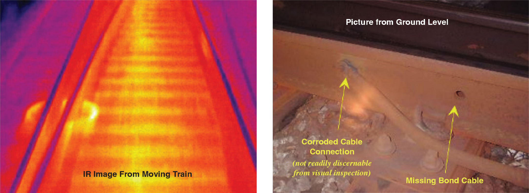
Long Description.
The IR image shows a rail track. The photo shows a picture taken from ground level with arrows pointing to the corroded cable connection (not readily discernable from visual inspection) and missing bond cable.

Long Description.
The IR image taken from a moving train shows a rail track. The photo shows a picture taken from ground level with an arrow pointing to the loose cross-bond connection bolts.
Field Measurements
Measuring the actual conditions in the field may be required to resolve IJ arcing issues. This effort can be time-consuming and expensive, but, in some cases, it may be the only way to understand the exact conditions that result in IJ arcing. This effort can require significant logistics, effort, and expense to perform, and it should be the last resort when other efforts do not identify the issues contributing to IJ arcing.
Some transit vehicles may have onboard monitoring systems that may record information useful for investigating IJ arcing. Items such as propulsion mode, third-rail voltage, power draw, return current voltage and amperage, and more, can be useful in investigating IJ arcing. If this information is available, it would be the first dataset used for the research effort, since it is available with little effort. It may take some effort to correlate this information with the times and locations where arcing occurred.
If wayside measurements are required, video of the offending IJs should also be recorded so the data can be correlated with the actual field conditions (e.g., position of consist, magnitude of arcing). Before-and-after data recordings can also be useful to validate the effectiveness of the changes, if they are implemented so the actual effects of those changes can be understood, and to ensure other problems are not created by the changes.
Data should be recorded with a plan for an array of tests that include train movement direction and a variety of propulsion-mode scenarios, such as coast mode, acceleration, braking, low speed, full speed, and more. The data from the various propulsion modes can provide a range of data that can aid in identifying the conditions that may contribute to IJ arcing and identify the conditions when arcing is not occurring. If train length is suspected as contributing to the issues, train passes using a variety of train lengths should also be recorded. Figure C-5 shows an example schematic of the measuring instrumentation layout used to investigate IJ arcing.
Some upfront effort is required before taking the field measurements. What is to be measured, the locations where measurements are to be performed, and the type and range of the instrumentation must be determined. The sampling frequency is also important—if the frequency is too low, data spikes will be missed; if the frequency is too high, the amount of data to store and process will increase.
The trackway is an unforgiving environment. The measuring equipment used must be weatherproof and vibration proof, able to withstand the impacts generated as trains pass over nearby rail

Long Description.
The layout shows two tracks with impedance bonds on the left end, cross bonds in the middle, and an equalization bond on the right end. The insulated rail joints are across each track and the cross bond. The rails in each track are marked east rail (upper) and west rail (lower).
joints and special trackwork, and protected from poor wheel conditions and rail corrugation. If the testing is performed in tunnel areas, the equipment should be waterproof since passing trains can carry rainwater in from open areas. Electrified railways can have significant electrical and radio frequency noise in the trackway, both from the wayside equipment and passing trains. Magnetic fields can be generated by the traction power system and passing trains. Shielding of the measuring equipment can be important, since electrified railways can expose the measuring and recording equipment to ensure accurate data. When designing the setup of the measuring system, it is imperative that the measuring setup is passive to train control, TPNR, and on-train equipment so the measuring equipment does not affect the integrity of those systems when the measurements are taken.
This page intentionally left blank.


