Evaluating and Delivering Advanced Driver Assistance Systems (ADAS) Education: A Guide (2025)
Chapter: Appendix E: Aid for Identifying Opportunities for Confusion in ADAS Information

APPENDIX E
Aid for Identifying Opportunities for Confusion in ADAS Information
The purpose of this aid is to help practitioners identify content in ADAS materials that may be inaccurate, could cause confusion, or has the potential to be misunderstood by the audience. The aid includes guidance for identifying concerns in both textual and visual information.
Types of Opportunities for Confusion
During the research teamʼs review of educational materials in Phase I, they flagged any content that contained potentially inaccurate information. Operationally, researchers documented materials that raised any question about the meaning or accuracy of the information, including when information seemed to contradict information given elsewhere by that source. Most of the flagged concerns were related to the use of ambiguous or inconsistent language rather than information that was strictly inaccurate. For instance, content may be accurate in a certain situation, context, or specific implementation of ADAS but inaccurate in other circumstances. Therefore, the researchers labeled these concerns as “opportunities for confusion.” Though not all the concerns can be neatly classified, the observed issues generally fell into four categories:
- Different types of ambiguous content, including content that is vague, technical, or uses idioms
- Inaccurate content
- Inconsistent content
- Lack of context
Some opportunities for confusion may fall into more than one category. The lists below show several examples for each of these categories.
Ambiguous Content
Ambiguous: Using Vague Language
When following another vehicle, ACC keeps your vehicle at a safe distance.
“Safe” is a subjective term that means different things to different people. It can also mean different things in different driving scenarios.
The system detects objects . . .
When an obstacle is detected . . .
The labels “object” and “obstacle” provide very little information. Does detection of an object depend on its size, color, shape, or material composition? Provide examples of the specific types of objects or obstacles the system is designed to detect.
AEB will brake to avoid collisions.
This statement could be interpreted by some learners to mean that AEB is capable of avoiding all collisions. Instead use a statement like “AEB may brake to avoid or mitigate a collision with a vehicle detected in front of your vehicle.”
Ambiguous: Using Technical Language
A telltale will appear . . .
Not every learner will understand the word “telltale,” which has a technical definition. Provide a definition for the word or choose a synonym that is easier to understand.
A brake jerk warning activates when a collision threat is detected . . .
Not every learner will understand the phrase “brake jerk warning,” but the individual words are familiar enough that the learner might make assumptions about what it means. Provide a clear description of how the vehicle will behave.
When system operating conditions are met . . .
A learner may not understand what “operating conditions” means. Include an example to help clarify. For instance, “For the ADAS to be available, the vehicle must be moving at least 20 mph.”
Ambiguous: Using Idioms
ADAS is like a guardian angel looking over your shoulder.
Idioms like “guardian angel” can be unique to a specific language or culture and may be interpreted differently by different people. When a phrase like this is used in the context of ADAS, it might lead learners to believe they are always protected and can be less attentive to the driving task.
If the systems detects that a car is a little too close for comfort . . .
“Too close for comfort” is an idiom that can have different meanings to different people. A distance that is comfortable for one person might be too close for others. Instead, give a precise description about how the system determines when a vehicle is close enough to warrant a response.
Inaccurate Content
ACC is a system you can set and forget
When ACC is active, it is in charge of the speed. . . .
These phrases are inaccurate descriptions of ACC. They suggest that ACC automates the driving task, and that the driver does not need to attend to driving. Avoid using language that minimizes the driverʼs responsibility when using ADAS.
A video or image shows the driver using ADAS without their hands on the steering wheel.
Showing a driver without their hands on the steering wheel suggests it is an acceptable way to use ADAS. This is not correct.
Describing lane keeping assistance (LKA) as a component of active driving assistance (ADA).
This description is not accurate. LKA provides momentary lateral control to avoid lane departures. Lane centering assistance (LCA) provides driving control assistance. ADA is commonly defined as the simultaneous use of LCA and adaptive cruise control (ACC).
Inconsistent Content
Audio narration in a video describes how ACC may lose tracking when following a vehicle through curves; however, the video shows multiple instances of ACC being used in curves.
Verbal information (narration or written text) should align with the visuals being shown in the video. Showing the ADAS working when a potentially limiting condition is present undermines the message about the limitation.
Description of AEB in text states it responds to forward traffic ahead, but the image shows the AEB responding to a vehicle turning across its path.
If the AEB message is about vehicles in the forward path, ensure that the words and image align. If the intent is to show AEB responding to turning traffic in its path, include that information in both the text and the image. Although some AEB systems may respond to turning traffic, not all have this capability.
Using the same icon (foot on pedal) for graphics illustrating FCW and AEB.
The warning (FCW) requires the driver to initiate braking while the intervention (AEB) applies braking automatically. It is inconsistent and misleading to use the same icon to represent two different constructs.
Describing the same ADAS differently (e.g., using different verbs or using different images) across the same material or across multiple materials created by the same organization.
Changing a word or phrase or making a slight modification to an image can change how a learner interprets the content. If repeating content, be consistent with word and image choices.
Lack of Context
Materials that include images without a caption and do not align with other nearby content.
Placing an image that illustrates how weather can affect an ADAS with content that describes function rather than limitations.
An image should enhance the understanding of the content. Using an image without an explanation or placing it with unrelated content can lead to confusion or misunderstanding.
A video shows alerts being activated without any text or narration to describe what the alerts mean.
Although showing alerts in videos can be useful, not describing why the alerts are happening can confuse the viewer or lead them to make assumptions about the reason for the alerts.
Recommendation to use longest ACC setting without any explanation why.
Providing advice about which following setting to use for ACC without an explanation lacks context and does not help the learner understand the potential impacts of different settings.
Reviewing Visual Content for Opportunities for Confusion
Like textual information, content like images or videos can also contain opportunities for confusion. Table E-1 presents a checklist practitioners can use to help review visual content and identify opportunities for confusion. It is followed by two examples that demonstrate how practitioners can review images and identify ways they can be approved.
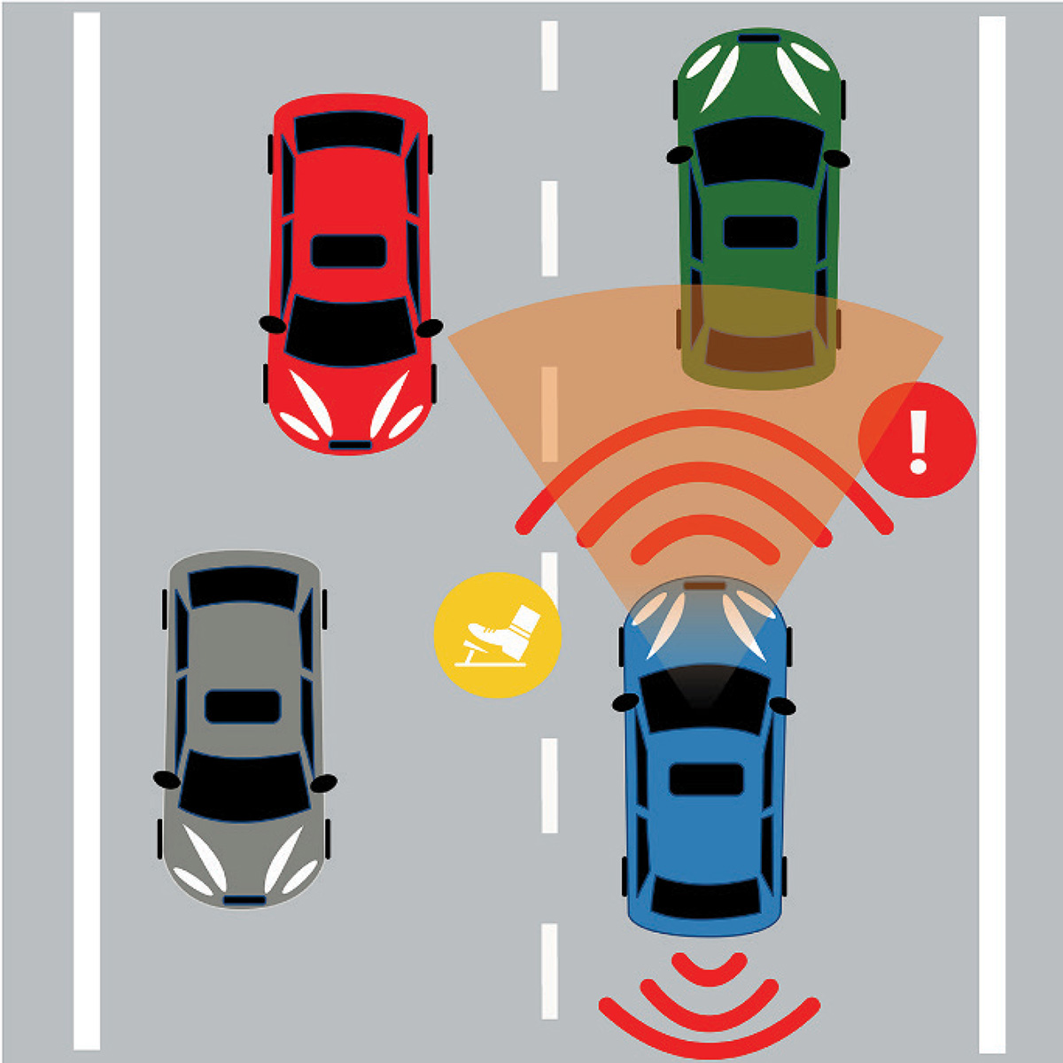
Image Review Example: Automatic Emergency Braking
Figure E-1, which aims to illustrate AEB, includes several elements that could be inaccurate or confusing. Because the image is not accompanied by a caption or legend, learners are left to their own interpretation of what everything means. If the red lines placed at the front of the blue vehicle

Long Description.
The content is presented as a checklist in four sections, with check boxes before each list. Objective of the image: What does the image contribute to the learning objective or objectives? Is it clear which ADAS features are being illustrated? If an image includes more than one ADAS, does presenting the ADAS together in the same image contribute to the learning objective? If not, consider having separate images for each ADAS. Is the image placed with textual content that provides context and additional relevant information? Is the context between the image and text consistent? Representation of ADAS sensors: Does the image accurately reflect where the sensor is located on the vehicle? Even within the same type of ADAS, the type of the sensor used can vary. Radar sensors used by some FCW, AEB, AES, and ACC are commonly located in the front grille of the vehicle. Many vehicles have forward facing cameras at the top center of the windshield. Lane support systems such as LDW, LKA, and LCA may use these cameras along with some FCW, AEB, AES, and ACC systems. Sensors used by most BSW systems are typically located in the side or rear side panels or in the rear corners of the vehicle. Does the image accurately depict the range, that is size and shape of the area observed by the sensor? Though multiple ADAS may use radar, typically the range for ACC radar sensors extends beyond the range used by FCW, AEB, and AES. Long range radar typically detects vehicles within a field shaped like a cone. In most BSW systems, the sensors monitor only the adjacent lane on each side of the vehicle. An image that shows sensing across multiple side lanes, such as two lanes, may not be accurate. Consider the scale of the sensor range relative to other objects in the image. If the range cannot be shown in scale with the other objects, label the image as not to scale. Symbols within the image: Does including the symbol in the image contribute to the objective? Is the meaning clear? Are the symbols explained with a legend or a caption placed with the image? Avoid explaining the symbology in text content separate from the image. If symbols are intended to communicate how the ADAS functions, it needs to be clear whether the symbol represents an action a driver should take, such as the driver must steer or brake, or the control inputs the ADAS will make, such as the LKA will steer or the AEB will brake the vehicle. Does the position of the symbol in the image correspond to the ADAS feature it represents? For example, a symbol for FCW should be placed at the front of vehicle. Is a symbol for LDW placed near the lane on the appropriate side of the vehicle? If materials will include multiple images, is the symbology consistent across the images? Does the driving environment, including the roadway type and features, shown in the image correspond to the conditions in which the ADAS feature is designed to operate? For example, if an ADAS is intended for highway driving, do not show it being used on a city street. Consider posted or implied speed limit, number of travel lanes in each direction and presence of other traffic, presence of intersections, traffic controls, road curvature, hills, shoulders, weather conditions. Are the lane markings shown in the image appropriate, such as dashed versus solid, white or yellow, presence of fog line on edge of roadway? Are the vehicles placed appropriately for the direction of travel indicated by the lane markings? Are the vehicle types and their placement on the road appropriate for the purpose of the image? For example, an image illustrating LDW should place the vehicle near the lane edge. If illustrating nominal use of FCW or AEB, place vehicles near the center of same lane. Consider the scale and relationship between the objects in the image. Is the vehicle size appropriate relative to the lane width? Is the proximity between the vehicles realistic and aligned with the ADAS functionality? Consider whether a not to scale label would be appropriate.
Long Description.
The illustration of automatic emergency braking. A blue car in the right lane approaches a green car directly ahead. Radar waves extend from the blue car toward the green car, with an alert symbol near the green car. Additional radar waves appear in front of and behind the blue car. A yellow warning icon is shown between the blue car and the green car. Other cars are visible in the left lane, one gray car in front and one red car behind.
are intended to represent the AEB sensor range, the forward distance covered is very small (only about half a car length). The orange sector that originates from the windshield suggests the AEB is also using information from a forward-facing camera. The image includes a sensor at the rear of the vehicle that is unrelated to AEB. The warning symbol (exclamation mark in red circle) may lead to confusion because the driver may assume that AEB will only warn the driver, but AEB is designed to brake the vehicle if it determines that a frontal crash is imminent. The meaning of the yellow symbol is ambiguous. It shows a foot over a pedal. Does this mean that the driver must or should brake, or does the gap between the foot and the pedal mean that the vehicle will apply the brake? The road type shown in the image accurately represents where AEB can function, but the center lane marking is incorrect for a US roadway with vehicles traveling in opposite directions. Relative to the width of the vehicles, the driving lanes appear wider than typical roadways.
Several changes can improve this image. First, remove the unrelated sensor from the rear of the vehicle to avoid confusion and keep the focus on the AEB. Reduce the width of the driving lanes to be in scale with the size of the vehicles. Adjust the scale of the red AEB sensor range so its size and shape more accurately represent the monitored area. Add a note to inform learners that the sensors are not drawn to scale. Position the detected vehicle at the edge of the sensor range and align the AEB-equipped vehicle behind it. While a warning symbol is somewhat standardized, it is difficult to communicate vehicle action through symbols. Remove the yellow symbol as its meaning is unclear. Since AEB provides momentary braking assistance, a warning symbol alone is inadequate. Either remove the warning symbol or pair it with text indicating that an alert may occur before braking. Correct the center road markings to yellow to indicate opposing traffic. Add a legend to define the lines extending from the vehicle, the orange sector, and the meaning of any symbols or icons. Last, make sure the image is placed alongside consistent, clearly written text context.
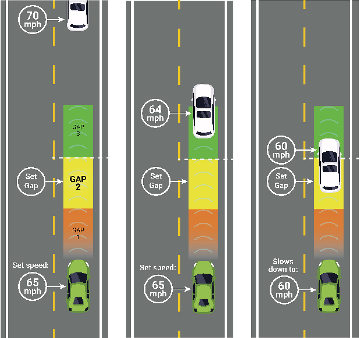
Image Review Example: Adaptive Cruise Control
Figure E-2 shows a series of three images designed to represent how radar-based ACC responds when a vehicle is detected ahead. A review of this visual content identified several
Long Description.
The illustration for adaptive cruise control in three side-by-side panels. In the left panel, a green car follows a white car in the same lane. The white car runs 70 miles per hour, while the green runs at a set speed of 65 miles per hour. In the middle panel, an orange, yellow, and green zone labeled Gap 1, Gap 2 (the set gap), and Gap 3 extend forward from the green car toward the white car. In the middle panel, the white car runs at 64 miles per hour, and the green car is set to 65 miles per hour and is partially in the green zone. A green zone is shown between the two cars with curved radar waves. In the right panel, the white car runs at 60 miles per hour, and the green car slows down to 60 miles per hour and is partially between the green and yellow zones. The gap zone is displayed in green and orange bands with radar waves extending between both cars.
concerns. The meaning of the colored zones and curved lines in front of the green vehicle are not defined. Front radar typically detects objects in a cone-shaped area, but the zone shown in the images is rectangular. If the curved lines represent the zone monitored by the radar, the range distance represented is not accurate. In the image, the detection range ends at the far edge of the third following gap. ACC radar will detect vehicles much farther ahead than the systemʼs longest following gap. Specifically, the left image appears to represent a vehicle that is traveling a little more than four car lengths ahead, a range that would certainly be in the radar detection zone.
In the situation shown in the center image, the ACC-equipped vehicle would not be traveling at the set speed; it would already be slowing in response to the white vehicle ahead, which is traveling slower and has nearly reached the boundary of the selected following gap. The right image shows the white detected vehicle inside the selected gap, which is not an accurate representation; ACC will adjust the vehicleʼs speed to maintain the selected gap. In the US, a road configuration of this type would be appropriate for ACC use, but generally it would not have a speed limit of 65 or 70 mph, which is the travel speed shown in the images. Therefore, the image implies it is appropriate to speed and to use ACC while doing so.
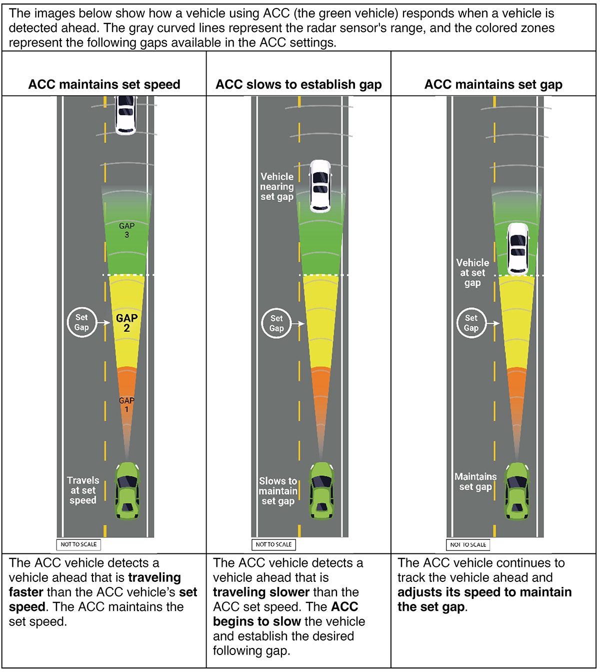
Improving the Images
Several adjustments could be made to improve the quality of these images. First, add text that explains the purpose of the figure, identifies which vehicle is equipped with ACC, and explains what the gray curved lines and colored zones represent (i.e., the radar sensor range and the available gap settings for the ACC, respectively). Add titles and captions to each image that describe what the ACC is doing in each situation.
In each image, adjust the radar range shape so the sensor is narrow at the vehicle and widens as the distance from the vehicle increases. Extend the radar range beyond the ACC gap sizes to the edge of the image. Add a caption to indicate that the images are not to scale.
Since the speeds are not necessary to illustrate how ACC responds to vehicles detected ahead, remove the speed labels and replace with labels about what the vehicle is doing. Adjust the placement of the detected vehicle so it is farther away from the ACC vehicle in the center image and outside the zone for the set gap in the right image. Figure E-3 shows the new images after making these updates.
Long Description.
The illustration for adaptive cruise control across three panels. In the left panel, a green car travels at its set speed behind a white car in the same lane. Coloured zones extend forward from the green car, labeled Gap 1 in orange, Gap 2 in yellow (the set gap), and Gap 3 in green. The heading reads ACC maintains set speed. The caption reads the ACC vehicle detects a vehicle ahead that is traveling faster than the ACC vehicleʼs set speed. The ACC maintains the set speed. In the middle panel, the white car is closer, and the text states Vehicle nearing set gap. The green car slows down to maintain the set gap, shown by the white car partially in the green zone. The heading reads ACC slows to establish a gap. The caption reads the ACC vehicle detects a vehicle ahead that is traveling slower than the ACC set speed. The ACC begins to slow the vehicle and establish the desired following gap. In the right panel, the white car is positioned at the set gap distance from the green car. The zones extend evenly between them in orange, yellow, and green bands. The text notes Vehicle at set gap. The heading reads ACC maintains set gap. The caption reads the ACC vehicle continues to track the vehicle ahead and adjusts its speed to maintain the set gap.
| Abbreviations and acronyms used without definitions in TRB publications: | |
A4A |
Airlines for America |
AAAE |
American Association of Airport Executives |
AASHO |
American Association of State Highway Officials |
AASHTO |
American Association of State Highway and Transportation Officials |
ACI–NA |
Airports Council International–North America |
ACRP |
Airport Cooperative Research Program |
ADA |
Americans with Disabilities Act |
APTA |
American Public Transportation Association |
ASCE |
American Society of Civil Engineers |
ASME |
American Society of Mechanical Engineers |
ASTM |
American Society for Testing and Materials |
ATA |
American Trucking Associations |
CTAA |
Community Transportation Association of America |
CTBSSP |
Commercial Truck and Bus Safety Synthesis Program |
DHS |
Department of Homeland Security |
DOE |
Department of Energy |
EPA |
Environmental Protection Agency |
FAA |
Federal Aviation Administration |
FAST |
Fixing Americaʼs Surface Transportation Act (2015) |
FHWA |
Federal Highway Administration |
FMCSA |
Federal Motor Carrier Safety Administration |
FRA |
Federal Railroad Administration |
FTA |
Federal Transit Administration |
GHSA |
Governors Highway Safety Association |
HMCRP |
Hazardous Materials Cooperative Research Program |
IEEE |
Institute of Electrical and Electronics Engineers |
ISTEA |
Intermodal Surface Transportation Efficiency Act of 1991 |
ITE |
Institute of Transportation Engineers |
MAP-21 |
Moving Ahead for Progress in the 21st Century Act (2012) |
NASA |
National Aeronautics and Space Administration |
NASAO |
National Association of State Aviation Officials |
NCFRP |
National Cooperative Freight Research Program |
NCHRP |
National Cooperative Highway Research Program |
NHTSA |
National Highway Traffic Safety Administration |
NTSB |
National Transportation Safety Board |
PHMSA |
Pipeline and Hazardous Materials Safety Administration |
RITA |
Research and Innovative Technology Administration |
SAE |
Society of Automotive Engineers |
SAFETEA-LU |
Safe, Accountable, Flexible, Efficient Transportation Equity Act: A Legacy for Users (2005) |
TCRP |
Transit Cooperative Research Program |
TEA-21 |
Transportation Equity Act for the 21st Century (1998) |
TRB |
Transportation Research Board |
TSA |
Transportation Security Administration |
U.S. DOT |
United States Department of Transportation |

Transportation Research Board
500 Fifth Street, NW
Washington, DC 20001