Active Traffic Management Strategies: A Planning and Evaluation Guide (2024)
Chapter: 7 Design Considerations for ATM

CHAPTER 7
Design Considerations for ATM

Chapter Highlights and Objectives
This chapter focuses on key elements to consider when designing active traffic management (ATM) systems. It addresses the civil, technology, and software components that need to be designed to deliver an ATM strategy. Building on prior chapters where technologies and ATM strategies are explained in detail (namely Chapter 2), this chapter identifies design issues and considerations associated with the range of technologies and systems typically found in freeway and arterial ATM implementations. The remainder of this chapter presents the following sections:
- Context for ATM Design in Different Environments. Provides a summary of unique operating environments for ATM, including freeway, arterial, and temporary installations.
- Physical ATM Design Considerations. Outlines the civil components and key considerations related to ATM infrastructure, including structures, pavements, signage, markings, and geometries.
- Systems and Technology-Related Considerations. Includes field technologies typically included in ATM strategies and communications infrastructure.
- Final Remarks. Discusses the ATM design considerations presented in this chapter.
- Chapter 7 References. Includes a list of all references cited within this chapter.

Context for ATM Design in Different Environments
The design process for ATM builds on concepts and requirements that were featured in earlier chapters and focuses on detailed design documentation, which includes plans, specifications, estimates, and systems engineering documents that support the hardware and software included in the proposed design. Some ATM strategies may require very little in terms of traditional engineering design (and as a result, construction). Strategies, such as adaptive traffic signal systems, transit signal priority, and adaptive ramp metering, represent cost-effective solutions that can be built into existing signal equipment and updated central system software. In some instances, additional communications infrastructure or detection capabilities may need to be installed to support these strategies. Similarly, agencies seeking to implement shoulder operations to relieve bottlenecks during periods of high demand on a corridor may find that they can accomplish this strategy with signage, striping, and marking (with or without dynamic signage).
Separate, and in some cases parallel, design efforts will exist for the various elements that make up an ATM. These design components include the following:
- Civil elements: Includes roadway elements such as geometrics, pavement markings, striping, structures, gantries, and static signage. In some cases, roadway improvements may be needed
- to support ATM field equipment or ATM operations strategies, such as shoulder running or emergency pull-offs for responders.
- Field equipment: Includes technology infrastructure such as signals, ramp meters, dynamic signs (for VSLs and traveler information), detection and monitoring devices, and supporting communications. The communications network can include fiber-optic cables, wireless radio links, leased communication lines, and in some unique cases, cellular links to remote equipment.
- Central equipment: Includes communications and network components located within a physical space such as a traffic operations center, or through virtual spaces such as cloud-based hosting or software-as-a-service solutions. Central equipment integrates all the field equipment and provides the infrastructure to operate the technology installed in the field.
The field equipment includes CCTV cameras, message signs (dynamic, changeable, variable), detection devices, lane control signals, ramp meters, highway advisory radios, and other supplemental technologies as defined within the selected ATM strategies (FHWA 2023a).
Freeway Versus Arterial Installations
Historically, ATM deployments have been more common on freeways. With growing challenges on arterials and little room for adding capacity, ATM applications can be feasible solutions within local and arterial contexts. Freeway and arterial ATM applications differ in their scale, participating agencies, and design standards, which influences the approach to design as follows:
- Freeway installations are often larger in size, right-of-way is not as constrained, and speeds are faster.
- Arterial installations accommodate slower speeds and often consider the local environment, multimodal users such as bicycles and pedestrians, and the appropriateness of strategies, given the surroundings.
For example, consider a DMS on a freeway versus an arterial. A freeway DMS may be 10-ft tall and more than 30-ft wide. These types of installations might not be accepted or necessary on arterial roadways. A smaller trailblazer sign may be selected for arterial applications and will often be strategically positioned near major event venues, near freeway on- and off-ramps, or more generally at major decision points. The amounts of information that can be conveyed on both types of dynamic signs differ.
While some ATM applications (e.g., ramp meters) may be better suited for freeway systems, other solutions may only be appropriate for arterials. For example, bicycle and pedestrian ATM deployments, such as smart camera detection systems, can only be implemented at signalized intersections. In addition, these modes are not allowed on freeways. Arterial deployments experience interrupted operations through intersections while limited-access freeway operations do not. This operational difference impacts the approach and approvals related to design.
Temporary Installations
Temporary installations can vary in duration—some may span only days or weeks while others may continue for a year as a pilot or demonstration project. Examples of temporary installations include work zone and event management, wherein the installation is serving a particular temporary purpose. Figure 7-1 shows a VSL application for a work zone in Utah.
Examples of devices and strategies used in temporary installations include advanced warning devices such as DMS, traffic monitoring devices, VSL signs, portable and in-pavement lighting, and ancillary communications infrastructure to support these devices. These devices are in

(Source: Utah Department of Transportation).
addition to static signage, temporary striping and marking, and traffic control equipment such as barriers and cones (Ullman and Schroeder 2007). Specific examples include the following:
- Advanced warning devices such as temporary DMSs.
- In-pavement lighting to initiate merging.
- Traffic monitoring devices, including portable cameras.
- VSL signs and supporting technology.
- Nonconstruction communication such as solar- or battery-powered antennae for ITS devices.
- Integration of permanent ITS devices such as DMSs with custom messages for work zone management.
Temporary installations have different considerations than permanent installations. Temporary traffic control requirements are outlined in the MUTCD and should be followed as the foundation for work zone management (FHWA 2008). Temporary traffic control standards can be paired with standards related to the ATM technologies used in work zone management and for planned special events.
Pilot and demonstration projects are other examples where temporary equipment may be used and is often used to test a technology that may not yet be proven or widely accepted. Examples of demonstration projects include bus-on-shoulder, smart intersection improvements, and CVs. In each of these cases, the technology or operations are unknown, and therefore, permanent implementations may seem too risky for the agency. When designing a pilot or demonstration project, the following issues are possible considerations:
- Maintain the same design tenets as though the project followed a traditional capital improvement process if the intention is to keep the ATM system in place once proven successful.
- Consider how to accelerate project delivery. For example, fiber-optic installation may not be feasible; wireless communication may be more appropriate and cost-effective for a demonstration or pilot project.
- Engage approving agencies early and explore no-fee permits and expedited review opportunities. Focus on stakeholder needs to gain early buy-in and build consensus.
- Design with measurability in mind. Before-and-after studies are often ways to evaluate the impacts of a project across a range of potential measures.
Physical ATM Design Considerations
Introducing an ATM system along a corridor requires careful consideration of the civil components related to various elements of the strategy, such as lane geometry, pavement markings and signage, gantry design, maintenance of the system, access to interchanges, and other physical characteristics of the roadway. This section describes design considerations for each of the civil elements related to designing an ATM system.
Signage
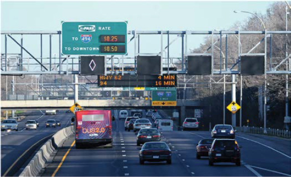
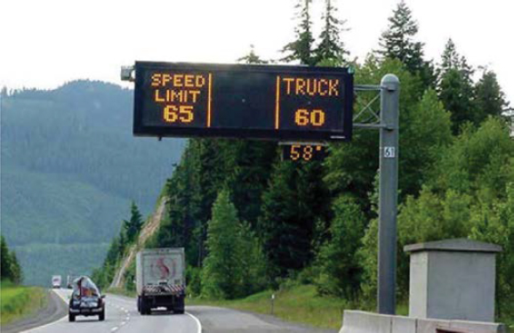
ATM implementations will need to consider existing signage along the corridor during the design phase. Existing signs (guide, warning, advisory, or regulatory) may be in the vicinity of a defined new gantry location. In this instance, it is feasible that a new structure can be designed that integrates dynamic and static signage onto one gantry structure. Gantry structures will need to account for the placement of static signs in relation to the lane control signs—either stacked vertically as shown in Figure 7-2 or placed to the side of the lane control signs at the ends of the gantry structures. It is the designers’ responsibility to avoid sign clutter or information overload while also meeting all design requirements for sight distance and sign placement.
In some cases, agencies may consider removing or streamlining existing signage to accommodate updated signage for an ATM strategy. Examples may include HOV lane displays or fixed speed limit signs being replaced by new dynamic signage on freeways or arterials. Dynamic signage does require power and backup communications to ensure that advisory and regulatory signs will remain functional. In general, the signage used in ATM displays requires FHWA approval. Currently, lane control messages are the only MUTCD-approved displays; the design and use of other sign messages, such as merging or caution messages, must be reviewed and approved by the FHWA. Additional details are provided in the Lane Control Signal (LCS) section of this chapter.
Interchange Geometrics
Interchange geometrics must be assessed when implementing adaptive ramp metering, dynamic junction control, or dynamic lane use. Ramp modifications may be necessary to accommodate additional capacity for ramp metering strategies. In addition, ramp modifications and
merges at the interchange may be required to accommodate lane configurations for dynamic shoulder use. These modifications can impact ramp bridge widths, ramp or mainline pavement markings, retaining walls under bridges, and other geometrics of the interchange. Designing an ATM system that will minimize geometric changes at interchanges is recommended to minimize construction costs of the system.
Shoulder as a Travel Lane
Using the shoulder as a travel lane introduces additional civil design requirements for the ATM system. Shoulder use can be implemented on either shoulder of the roadway. Design elements will include both pavement and signage designs. General design requirements that must be satisfied before using the shoulder as a travel lane include the following:
- Have the same width as a full travel lane, are made of the same material, and are designed similarly to a regular lane.
- Have no adverse superelevation.
- Be continuous.
- Be designed with a rollover rate that does not exceed 8 percent to address cross slope considerations (the rollover rate is defined as the algebraic difference in the rate of cross slope between adjacent travel lanes).
The design of the shoulder lane is at the discretion of the agency implementing the use of the shoulder as a travel lane. Effective design considerations should be applied when comparing the pavement and base designs relative to a general purpose lane. Institutional buy-in and agency coordination are important in successfully designing and implementing shoulder lane applications. For this reason, it is recommended to be well-versed in nontraditional shoulder treatments within the project’s jurisdiction and to determine whether there is policy to support it. In areas that are new to nontraditional shoulder uses, a demonstration or pilot project may be more appropriate. These types of programs are identified in the Temporary Installations section of this chapter.
Pavement Markings and Signage
Based on the ATM applications selected for implementation, pavement markings and signage changes may be needed. In areas where lane control displays are located, the use of dynamic pavement marking technology that can change the number of lanes available is not recommended; this overlap of technologies would create inconsistency and confusion with the application of more than one display per lane. Additional and enhanced pavement markings are needed to alert drivers to the availability of hard-shoulder running or emergency pull-off areas.
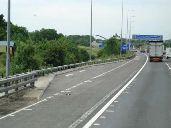
When the shoulder is not identified as a potential lane, a solid yellow line is used, as shown in Figure 7-3 from US-23 in Michigan. Laws frequently prohibit crossing the yellow lines except for emergencies. The use of a solid white line is recommended for use when the shoulder may be used as a travel lane. Generally, the MUTCD discourages crossing a solid white line, although it is not prohibited. In some states, it may be illegal to cross a solid white line; therefore, existing traffic control regulations must be confirmed during the design phase.
Static merge arrow pavement markings, in conjunction with warning signs, need to be used at the physical end of all shoulder lane sections of a corridor to denote the end of shoulder operation. Additionally, dynamic merge signs should be used, when possible, to provide enhanced warning of the shift in the road during weather conditions.
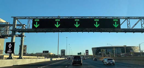
It is also possible to use pavement lighting to denote when the shoulder is open and closed. When the shoulder is closed, the lighting can create a yellow tapered line across the left lane to get motorists to merge right. When the shoulder is open, a white skip strip can be illuminated.
Emergency Pull-offs
Emergency pull-off areas or refuges provide a safe location for motorists who are experiencing an emergency to remove themselves from the flow of traffic (see Figure 7-4). These areas should be large enough to accommodate vehicles experiencing mechanical failure as well as those vehicles involved in a collision. In addition, these areas can be used by law enforcement or emergency vehicles, if necessary. These pull-off areas should be at least 14-ft wide and 200-ft long to provide adequate space for whatever purpose they need to serve. The spacing between the emergency pull-offs is largely determined by the availability of space and the anticipated demand based on the roadway characteristics; pull-offs can be spaced anywhere between 0.5 and 2.5 mi apart. Emergency pull-offs can be colocated with maintenance pull-off areas to cut down on required space and construction costs. The Regional Transportation Commission of Southern Nevada (RTCSNV) and the Nevada DOT (NDOT) design their emergency pull-off areas to be at a higher elevation compared to the mainline facility. These higher elevation points allow for strategically placed enforcement vehicles to park in plain sight. In some cases, the vehicles are unoccupied, but their presence deters speeding and unsafe driving practices.
Gantry Structures
Lane control signals and some dynamic signage installed for many freeway-based ATM implementations require structures that allow the placement of LCSs over the travel lanes. Gantries represent a significant cost element that must be considered when implementing certain ATM strategies; considerations include structure needs, communications and power, siting, and accessibility for maintenance of the gantry and any technology elements. Most often, new structures are designed to support the required design configuration, but in some cases, existing structures can be retrofitted to accommodate dynamic signage over each prescribed travel lane on the roadway. The following three design decisions need to be factored into the design of the gantry structures:
- Structure type.
- Structure width.
- Gantry spacing along the corridor.
In addition, guidelines related to the clear zone around the base of the structures and maintenance considerations associated with the preferred structure type are also presented in this section.
Structure Type
Typical structure types for ATM solutions have included truss or monotube structures. The type of structure must be determined before the true, detailed design development can begin. Determination of the structure type should include consideration of the following:
- A typical truss gantry may allow 1,200 sq. ft. of signage and 6,000 lb of weight. These design constraints apply to both full gantries (spanning one or both directions of travel and supported on both ends of the truss) and cantilevers (spanning only a single lane of the roadway and supported on one end of the truss).
- Some agencies do not have any existing standard monotube structures or the associated experience related to designing, installing, and maintaining the structures. If the monotube structure is new for an agency, it often would require a special structure design prior to procurement.
- The American Association of State Highway and Transportation Officials (AASHTO) Standard Specifications for Structural Supports for Highway Signs, Luminaires, and Traffic Signals (AASHTO 2013) renders mounting large DMSs to monotubes impractical due to seismic wind-loading issues. However, smaller signs can be safely mounted to the upright sides of the monotube structure.
During the preliminary design, the preferred structure type must be assessed, and the following considerations relative to each structure type noted:
- The foundation design for a typical truss gantry supports spans of 140 to 150 ft. Beyond this length, the foundation design must be enhanced to support the additional width. The specific foundation design needs should be determined and designed by a structural engineer to account for sign span, local/state design requirements, and the overall layout of the structure. Installation of a typical truss gantry requires a crane and lane closures; however, spans greater than 100 ft require two cranes and the potential for additional traffic control.
- Cantilever installations typically span over a single outside lane and are used for shoulder lane use only or as a supplement to full-span gantries. Cantilever installations also require less traffic control and construction costs when compared to a full-span gantry.
Depending on the location of LCSs designed within the ATM system, an existing bridge, signal pole, or other overhead structure may be an appropriate location for mounting new LCSs
and/or DMSs. In this case, a complete structural evaluation of the existing structure needs to be completed to verify that it can support the loading associated with the new device installations. Once approved, a retrofitted design is needed to capture the mounting of the new devices on the existing structures.
Structure Width
A key decision factor in determining structure type is the width the structure must span. While more common on freeways, gantry structures may be placed on arterials for event management, evacuations, and other special applications. Arterial structure specifications tend to be smaller in their structure size and foundation depth. Nonetheless, they are more constrained than highways and can experience challenges with insufficient right-of-way to house their posts and foundations. Their brightness can often impact surrounding uses, which requires assessing the potential impact on neighboring residences or businesses.
Most highways have two directions of travel and a median consisting of concrete barriers or open space. Designing a structure that crosses all lanes of travel in both directions is largely dependent on the number of lanes in each direction. A span that covers two or three lanes in each direction separated by a concrete barrier may be feasible; however, a roadway with four or five lanes in each direction or a roadway with a wide median (or a median occupied by another facility such as a reversible lane roadway or a transit guideway) may require individual gantries spanning each direction of travel. Existing structures such as bridges or supports for guide signs may be practical for mounting LCSs or ATM components. To accommodate the use of existing structures, it may be necessary to move or replace existing guide signs and equipment to new structures within the corridor.
Figure 7-5 and Figure 7-6 provide examples of the various structure widths that can be designed to accommodate certain lane configurations. Figure 7-6 shows a streamlined sign structure that is more cost-effective to install and maintain because it does not span the entire roadway.
Gantry Spacing
Early approaches to ATM design, particularly for urban freeways, leaned toward gantries placed at a density that allowed drivers to view both the gantry under which they are passing and the subsequent gantry at one time. In practice, this density yields an LCS placement approximately every 0.5 mi, depending on the environment along the corridor. Some agencies still use this spacing as a guide for design and placement. If gantries are used for purposes other than LCSs, they may be placed farther apart at key decision points. Sections with reduced sight distance due to horizontal and vertical curves and other limitations may require an increased
density for the placement of gantries. Some agencies are considering a gantry density that is between 0.5 mi and 1 mi between consecutive gantries, but certain ATM applications such as hard-shoulder running that introduce greater safety risks may require a higher density.
Each corridor should be evaluated for spacing and placement considerations; opportunities may exist to extend the space between signs without compromising safety and visibility.
Clear Zone
When designing the structural supports within the corridor, each structure must be evaluated with respect to the clear zone. If the supports fall within the clear zone, the design must include the installation of protection around the support. If a gantry foundation is required in the median, the design is dependent on the width of the median and the distance from the edge of the pavement. Protection can be provided by installing either a guardrail around the support or a median barrier foundation and a transition from the open ditch section to an enclosed median section with paved shoulders. The guardrail and median barrier also should be integrated with the overall cross section of the widened section.
Maintenance Considerations

Maintenance is discussed in further detail in Chapter 9—“ATM Operations and Maintenance.” This section identifies the design considerations that can impact maintenance. By incorporating future maintenance needs into the design, agencies can help minimize the impact of future maintenance activity. Gantry structures provide opportunities to design with the maintenance of the system in mind. Maintenance considerations include access to the equipment mounted on the structure and the complexity of traffic control required to perform maintenance activities. The following design considerations are recommended to mitigate future maintenance concerns:
- Structures should include a catwalk to allow easier access for maintenance crews.
- DMSs should provide walk-in service access to key components.
- LCSs should be hot-swappable or hinged to minimize the amount of time maintenance technicians must work over the travel lanes.
- A pivoting structure can be installed that allows maintenance crews to swing the sign over the shoulder during maintenance activities.
- Power and communications infrastructure should be designed on the outside of the structures for easier access.
- Controller cabinets should be placed in front of DMSs when possible so the technician can see the display while working in the cabinet.
Systems and Technology-Related Design Considerations
Traditional ITS field technologies apply to ATM design, including DMSs, CCTV cameras, ramp meters, and detection devices. This section introduces design considerations for each type of technology that could be used with each ATM strategy. Certain ATM implementations require a combination of technologies that traverse the entire corridor and require integration to support consistency in messaging and operations. In other cases, variations of ATM strategies can be applied to different segments of the same ATM corridor based on the required needs of each segment.
Each technology component will consist of several subcomponents (similar to a typical ITS project design) and can include the actual field device, the structure or equipment pole on which the field device will be installed, an equipment cabinet to house all necessary communications and controller equipment, and communications infrastructure from the field device to the cabinet and from the cabinet to the central equipment. Individual field device locations are likely to include a single equipment cabinet that can provide adequate capacity for the field equipment required. For gantry installations, some implementations have installed dual equipment cabinets to provide adequate capacity that accommodates the number of controllers and field equipment necessary to operate the devices included with a full gantry installation.
DMSs
DMSs—dynamic (also known as changeable, variable, or electronic) message signs are defined in Chapter 2—“ATM Strategies.” Chapter 2L of the MUTCD provides guidance related to the design characteristics of DMSs (FHWA 2023b). However, the MUTCD is currently undergoing an update. Updated MUTCD requirements may include pertinent information on DMS placement, design characteristics, and messaging standards. As such, the updated MUTCD should be consulted when released.

To help agencies develop requirements, testing and verification plans, and procurement packages for DMSs, the FHWA has developed model systems engineering documents for DMSs (FHWA 2018a). These documents can provide a starting point for agencies as they develop a concept of operations and sample requirements that can be tailored to specific DMS needs and applications.
DMS Placement
Factors to consider when installing permanent message signs for ATM deployments are similar to recommended siting requirements for traditional freeway management systems and include the following:
- DMSs should be located sufficiently upstream of known bottlenecks and high-crash locations to enable road users to select an alternate route or take other appropriate action in response to a recurring condition.
- DMSs should be located sufficiently upstream of major diversion decision points, such as interchanges, to provide adequate distance over which road users can change lanes to reach one destination or the other.
- DMSs should not be located within an interchange except for toll plazas or managed lanes.
- DMSs should not be positioned at locations where the information load on drivers is already high because of guide signs and other types of information.
- DMSs should not be located in areas where drivers frequently perform lane-changing maneuvers in response to static guide sign information or in merging or weaving areas.
DMS Design Characteristics
When designing DMSs, the following design characteristics should be used:
- DMSs used on roadways with speed limits of 55 mph or higher should be visible from 0.5 mi under both day and night conditions.
- Messages should be designed to be legible from a minimum distance of 600 ft for nighttime conditions and 800 ft for normal daylight conditions.
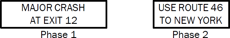
- When environmental conditions reduce visibility and legibility, messages with fewer units of information should be used, and single-phase messages should be considered. Table 7-1 provides an example of a message with four units of information (FHWA 2023b).
- Except in the case of a limited-legend DMS, DMSs should be used to supplement—not substitute—conventional signs and markings.
- DMSs should be limited to no more than three lines, with no more than 20 characters per line.
- There should be no rapid flashing, dissolving, or moving messages on signs.
- The minimum time an individual phase is displayed should be 1 second per word or 2 seconds per unit of information. The maximum cycle time for a two-phase message should be 8 seconds (MoDOT 2023).
- The spacing between characters in a word should be 25 to 40 percent of the letter height, between words in a message should be 75 to 100 percent of the letter height, and between message lines should be 50 to 75 percent of the letter height.
- The minimum letter height for DMSs should be 18 inches on roadways with speed limits of 45 mph or higher and 12 inches on roadways with speed limits of less than 45 mph. Using letter heights of more than 18 inches will not result in proportional increases in legibility distance.
- The width-to-height ratio of the sign characters should be 0.7:1.0. The stroke width-to-height ratio should be 0.2. The width-to-height ratio commonly is accomplished using a minimum font matrix density of 5 pixels wide by 7 pixels high.
- The luminance of DMSs should meet industry criteria for daytime and nighttime conditions. Luminance contrast should be 8 to 12 candelas per square meter for all conditions. The contrast orientation of DMSs should always be positive, meaning luminous characters on a dark or less luminous background.
- The colors used for the legends and backgrounds on DMSs should be consistent with the MUTCD guidelines for the common uses of sign colors.
- DMS technologies vary based on their light sources. Light-emitting diode (LED) is the most common and fairly standard for new installations. Full-color matrix signs provide the flexibility to display images beyond standard messages (see Figure 7-7).
Table 7-1. Example message with four units of information on a DMS.
| Question | Answer | Number of Information Units |
|---|---|---|
| What happened? | MAJOR CRASH | 1 |
| Where? | AT EXIT 12 | 1 |
| Who is the advisory for? | Drivers Heading to NEW YORK | 1 |
| What is advised? | USE ROUTE 46 | 1 |
SOURCE: FHWA 2023b, MUTCD Table 2L-1.
(Source: Florida Department of Transportation).
Figure 7-8 is an example of a two-phase message that could be developed from the four information units shown in Table 7-1.
DMS Technology
DMS technology options include sign illumination, size, and screen type. DMS panel lighting options are divided into two commonly used categories: light-emitting and light-emitting/flip disk hybrid. The light-emitting DMS uses an optical fiber or LED to form the pixel. The hybrid uses a flip disk in combination with light-emitting technology to form the pixel. The light-emitting and hybrid signs are the most commonly used because of their increased visibility. A more detailed description of DMS technology is presented in Chapter 2—“ATM Strategies.”

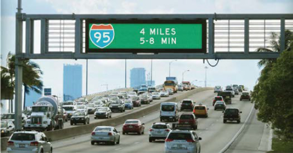
The size of the DMS factors into the design, cost, and application of ATM gantries. While most areas that have deployed ATM systems have used smaller DMSs in combination with lane control displays, some areas have pursued larger multilane DMSs, as shown in Figure 7-9. Multilane displays may be able to provide lane control displays as well as traveler information messages if the sign is large enough and the software system can accommodate it. Larger DMSs require additional construction costs and gantry support as compared to smaller DMS displays.
DMS technologies are offered in a variety of screen types, including modular, fixed character, and full matrix options. Each of these options can be provided in white, amber, or full-color displays. The type of message screen can affect the message that is chosen and the distance at which it can be read. The Arizona DOT uses fixed character signs. The New Mexico DOT uses full matrix signs. The preferred sign type used by the Virginia DOT varies by district. The three screen types (or matrix types) are described as follows:
- Modular matrix: This is the simplest matrix-type sign, comprised of character blocks. For example, a sign may have three lines with eight character blocks per line.
- Continuous line matrix: This type offers the ability to use proportionally spaced fonts, as opposed to the monospaced text displayed by discrete character blocks. The benefits include a more natural-looking sign with an easier-to-read message.

(Source: Kimley-Horn).
- Full-color matrix: This type is the most flexible and, thus, is most commonly used for new installations. The entire sign face is made up of elements or pixels that can be activated to display a message. These signs offer the ability to vary the height of characters, display simple graphics, and use proportionally spaced fonts.
LCSs
Lane control signs (LCSs) are defined in Chapter 2—“ATM Strategies.” The MUTCD contains documented guidance related to the design characteristics of LCSs in Chapter 4M (currently Chapter 4T, FHWA 2023c). The MUTCD is currently under review and potential revision.
LCS Design Characteristics
Detailed guidance for designing LCSs can be found in Section 4M.03—“Design of Lane-Use Control Signals” of the MUTCD (currently Chapter 4T, FHWA 2023c). A few design considerations necessary for LCSs include the following:
- Device requirements: LCSs should be designed at an appropriate minimum size to accommodate messaging requirements as defined for the ATM implementation. This signage includes lane control arrows, arrows with text, and speed limit messaging, as necessary. All LCSs should be compliant with the National Transportation Communications for Intelligent Transportation System Protocol (NTCIP).
- Spacing requirements: If the area to be controlled is more than 2,300 ft in length, or if the vertical or horizontal alignment is curved, intermediate lane-use control-signal faces should be located over each controlled lane at intervals that promote visibility across all lanes and do not impact safety. Agencies should undertake an analysis to determine optimal placement and frequency. This location should be such that road users will—at all times—be able to see at least one signal indication (preferably two) along the roadway and will have a definite indication of the lanes specifically reserved for their use.
- Placement requirements: LCS faces should be located approximately over the center of the controlled lane. All LCS faces should be located in a straight line across the roadway approximately at right angles to the roadway alignment.
- Supplemental signs: Supplemental signs could be used to explain LCS meaning and intent.
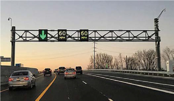
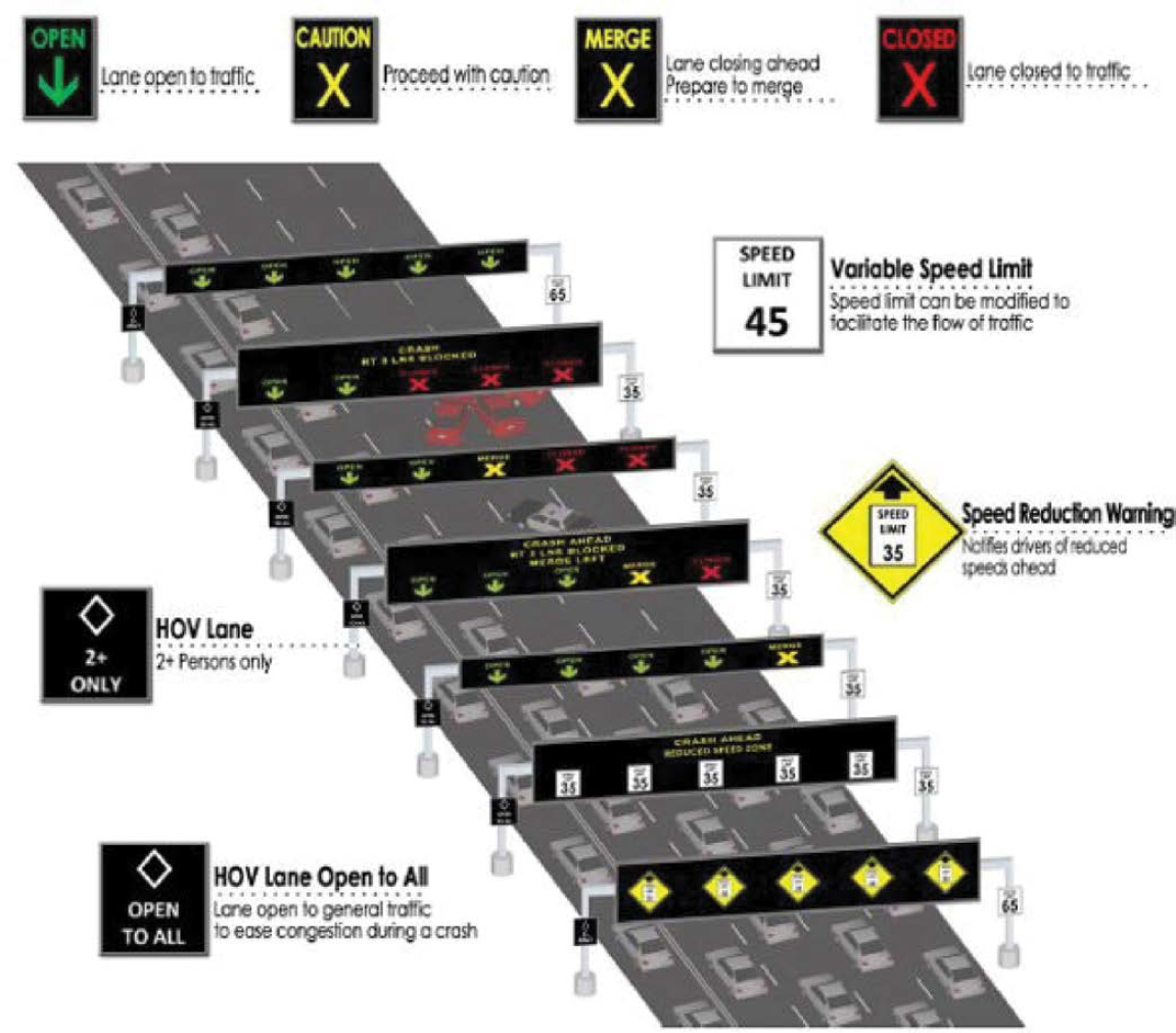
A variety of signage options are currently in use, and their applications are very specific to the needs of the ATM applications that were chosen for the area. The use of downward green arrows with words, yellow-angled arrows with words, red X signs with words, speed limit messaging, and diamond HOV indications with words are all options that have been implemented for ATM signage that are not in the current MUTCD. It is important to note that the FHWA is no longer granting experimental uses for nonconforming sign uses such as the yellow-angled arrows to indicate merge; if the project involves FHWA approval, other signage options may need to be selected. In the case of I-15 in Las Vegas, Nevada, the yellow-angled arrow was considered in the concept of operations, but a yellow X was implemented instead in agreement with FHWA (Kimley-Horn 2014). The consensus lane management displays are shown in Figure 7-10.
VSLs
Variable speed limits (VSLs) and their applications are defined in Chapter 2—“ATM Strategies.”
VSL Design Characteristics
The following design characteristics should be considered for VSLs implemented along a corridor (Campbell 2012):
- VSLs should be placed in 0.5- to 1-mi increments and downstream of each major entrance ramp between interchanges. VSL spacing guidelines were derived from traditional freeway management system design guidelines, which state that freeway DMSs should be located a minimum of 0.25 mi for each lane change that a driver would have to make to merge from the leftmost lane to the rightmost lane to exit. With the amount of equipment that is required to set up ATM, 0.25 mi would be too close and cause visual overload of signs and information for the driver; thus, a 0.5- to 1-mi spacing is recommended for ATM.
- Over-lane speed displays should be situated over the travel lane that the sign is controlling.
- VSLs over managed lanes (such as HOV or HOT lanes) can display speeds that are different from the general purpose lanes, depending on the needs and limitations of the local application. In all U.S. applications of this use, additional measures are typically taken to ensure a clear separation between the HOV or HOT lane and the general purpose lanes.
- VSL systems should be operated using either an automated or semiautomated approach. Both techniques use an algorithm that determines the maximum safe speed based on real-time field conditions. With semiautomated systems, the TMC operator is notified of the algorithm-recommended speed and has the option of approving or rejecting it. The semiautomated system is designed so that the speed limit will be automatically displayed if the operator does not respond within a certain period, using established agency business rules for the speed adjustments. With an automated system in place, speed limits must be verified and modified annually at a minimum. Regardless of what system is used, it is critical to determine the following parameters:
- Maximum posted speed limit allowed.
- Minimum posted speed limit allowed.
- Speed limit increments (5 or 10 mph).
- Speeds change frequency allowed.
- Period over which speed statistics are calculated.
As a cost savings, VSL signs can be designed as hybrid installations that include a static portion and a dynamic cut-in portion to display the effective speed. A message can be displayed on the relevant DMS whenever LCS displays are showing speeds lower than the posted speed limit. An example from Washington State is shown in Figure 7-11.

(Source: WSDOT).
Ramp Meters
Ramp metering can be deployed in various modes, including local fixed time, local adaptive, and system adaptive. As implied, fixed-time ramp metering operates at a fixed rate that may be varied by location and/or time of day but is not varied based on mainline or ramp demand. In the local-adaptive mode, the metering rate varies based on ramp demand and mainline demand upstream and downstream of the ramp. In system-adaptive ramp metering, the ramp metering rate is varied based on ramp demand and mainline flow over multiple ramps and mainline segments.
Regardless of mode, the primary function of ramp meters is to manage the rate of vehicles entering the freeway. Ramp metering systems are effective in reducing congestion on freeways by allowing vehicles to enter the facility in a more ordered manner, reducing merge/weave friction. They also can help limit mainline volumes and avoid flow breakdowns.
Several state DOTs have established ramp meter design guidelines or specifications to promote consistency in meter design and operations on a statewide level. Examples include the following:
- The California DOT (Caltrans) Division of Traffic Operations prepared a Ramp Metering Design Manual (Caltrans 2022). Caltrans updates this document every few years. This document has been expanded from the previous Ramp Meter Design Guidelines to include policies, design standards, and practices.
- The Oregon DOT, as part of its 2017 Traffic Signal Design Manual, includes a chapter on ramp meters. This chapter provides guidance on locations, signage and striping, and standard drawings to support design requirements (Oregon DOT 2017).
The MUTCD contains documented guidance related to the design characteristics of traffic control signals for freeway entrance ramps in Chapter 4P (FHWA 2023d), summarized below.
Ramp Meter Design Characteristics
When designing ramp meter signals for normal or adaptive operations, the following design requirements should be implemented:
- Ramp control signals, or any signage that is installed in association with the ramp meters, shall meet all the standard design specifications for traffic control signals and the MUTCD.
- The signal face for freeway entrance ramp control signals shall be either a two-section signal face containing red and green signal indications or a three-section signal face containing red, yellow, and green signal indications.
- If one or more lanes are present on an entrance ramp and the ramp control signals are operated such that green signal indications are always displayed simultaneously to all lanes on the ramp, then a minimum of two signal faces per ramp shall face entering traffic.
- If more than one lane is present on an entrance ramp and the ramp control signals are operated such that green signal indications are not always displayed simultaneously to all lanes on the ramp, then one signal face shall be provided over the approximate center of each separately controlled lane.
- Additional side-mounted signal faces should be considered for ramps with two or more separately controlled lanes.
- Ramp control signals shall be located and designed to minimize their viewing by mainline freeway traffic.
- Ramp control signals may be placed in the dark mode (no indications displayed) when not in use.
- Ramp control signals may be used to control some, but not all, lanes on a ramp, such as when nonmetered HOV bypass lanes are provided on a ramp.
- The required signal faces, if located at the side of the ramp roadway, may be mounted such that the height above the pavement grade at the center of the ramp roadway to the bottom of the signal housing of the lowest signal face is between 4.5 and 6 ft.
- For entrance ramps with only one controlled lane, the two required signal faces may both be mounted at the side of the roadway on a single pole, with one face at the normal mounting height and one face mounted lower.
- All ramp control signs should be NTCIP-compliant.
A key consideration in ramp meter design is detection. In a dynamic ramp metering operation, stop bar and spill-back detection is typically required. A spill-back detector is placed to detect whether ramp queues are spilling back into the arterial network. If so, it dynamically adjusts the meter to allow more vehicles to enter the freeway or turns off the meter to relieve the queue. For adaptive ramp metering applications, mainline detection upstream and downstream of the ramp are required. In local ramp metering, typically all the detection is tied into a local ramp meter controller, and the controller modifies the metering rates. In a system-adaptive ramp metering application, the ramp meters are networked and tied to a central management system. Specific detection schemes will vary by the type of algorithm used when implementing adaptive or dynamic ramp metering.
Ramp Meter Algorithms
Adaptive ramp metering utilizes traffic-responsive or adaptive algorithms (as opposed to pretimed or fixed-time rates) that can optimize either local or system-wide conditions. Adaptive ramp metering can also utilize advanced metering technologies such as dynamic bottleneck identification, automated incident detection, and integration with adjacent arterial traffic signal operations.
Table 7-2 presents an overview of several algorithms currently available and presented in Ramp Metering: A Proven, Cost-Effective Operational Strategy—A Primer (Mizuta et al. 2014).
In an ATM approach, real-time and anticipated traffic volumes on the freeway facility will be used to control the rate of vehicles entering the freeway facility. Based on the conditions, the ramp meter rates will be adjusted dynamically.
CCTV Cameras
Closed-circuit TV (CCTV) camera systems provide the ability to visually confirm an incident and its impact and monitor general traffic conditions from a remote location. Both freeway and arterial ATM implementations can use CCTV to support real-time monitoring. CCTV is also used to ensure that closed lanes or shoulder lanes are clear of objects or stationary vehicles prior to opening the lane. With this ability in place, agency staff can quickly determine the appropriate action needed to mitigate traffic impacts when an incident occurs and provide valuable information to emergency service providers and other agencies.
CCTV Technologies
Several CCTV technologies are available on the market, and several functions within the different technologies may be necessary to meet the requirements of the system. The use of full pan-tilt-zoom (PTZ) CCTV cameras is recommended to provide visual coverage of the entire corridor. However, adjusting the viewing angle of the camera may create an unmonitored area of the shoulder—violating safety requirements if the shoulder is used as a travel lane. Thus, the use of fixed cameras is recommended for shoulder lane monitoring. A standard color camera is preferred in the ITS arena, including for ATM applications. Standard color CCTV cameras provide the following functions and features:
- Internal digital signal processing.
- Automatic compensation for fluctuations in light levels.
- Easy field-of-view settings during camera installation.
- Digital zoom capabilities.
- Text superimposition on images.
- Low-light video integration for nighttime viewing.
- Pressurized enclosure for a clean and dry camera environment.
- Optional switch to black and white (in some cameras) under low-light conditions.
- NTCIP-compliant.
A range of CCTV technologies are in operation throughout the country, including (1) both serial-based (older analog) and Internet protocol (IP)–based (modern digital) technologies, (2) both fixed CCTV cameras that provide a fixed viewing area with limited zoom and resolution capabilities, and (3) full PTZ cameras that provide a full viewing range and higher-resolution images. IP-based systems transmit video across data networks in digital form and provide a higher-resolution image than their serial-based counterparts. Resolution and frame rates are key
Table 7-2. Description of example algorithms.
| Algorithm | Control Type | Description | Used By |
|---|---|---|---|
| ALINEA | Local | Metering rates are determined based on occupancy data collected from mainline loop detectors located downstream from the meter. The goal is to maximize the mainline throughput by maintaining occupancy values below the target threshold. | Other algorithms |
| Corridor Adaptive Ramp Metering Program (CARMA) | System | Metering rates are determined based on mainline speeds and prevailing local controller conditions, which are then optimized over each freeway direction. CARMA assumes that a ramp can allow maximum vehicles when the speed is high and should allow no vehicles when the speed is near optimal. | Kansas City, Missouri |
| Heuristic Ramp Metering Coordination (HERO) | System | HERO uses the ALINEA algorithm as the foundation for managing local conditions. When ramp queues meet threshold conditions, the control algorithm is activated and assigns restrictive metering rates to upstream ramps to balance downstream conditions. | Melbourne, Australia |
| Fuzzy Logic | System | This algorithm incorporates ramp queues and makes them integral to managing and controlling the freeway system. This algorithm controls multiple ramps, uses more comprehensive mainline and ramp inputs, and uses different heuristics, which allow for the most flexibility when determining metering rates for changing local conditions. | Seattle, Washington; Miami, Florida |
| Stratified Zone Metering (SZM) | System | This algorithm operates on density measurements and requires detection upstream of the ramp merge, at mainline exit ramps, and on the mainline to sustain the overall objective of a higher total volume exiting a zone than entering a zone. SZM attempts to rebalance the increase in mainline density by making the other meter rates in the active zone more restrictive. Ramp queue wait times are managed by a separate algorithm function. | Minneapolis, Minnesota |
| System-wide Adaptive Ramp Metering (SWARM) | System | Metering rates are calculated based on the current density, the required density, and the number of vehicles that should be removed or added to the freeway zone between each ramp. Additional upstream ramps are called to action when a single ramp has exceeded its capacity to balance the zone density. SWARM provides advantages for mixed ramp controls, allowing some ramps to be operated locally, manually, or with a different algorithm. SWARM will adapt to distribute wait times equally among ramps. | Orange County, California; Portland, Oregon |
SOURCE: Mizuta et al. 2014.
factors in communication network bandwidth utilization. Where fiber-optic or robust wireless communication exist to connect ATM technologies to a centralized ATM system, a medium-range resolution with a high frame rate will allow corridor operators to view real-time conditions without any lag time.
To support agencies in developing requirements and procurement documents for CCTV cameras, FHWA has developed model systems engineering documents for CCTV (FHWA 2018a). This resource can be used when developing a concept of operations, requirements, and a procurement package. This resource also provides sample requirements and sample plans for verification and validation to support the full cycle of systems engineering.
Recommended CCTV Locations
When determining CCTV locations, the following design recommendations should be followed:
- Cameras used in low-light conditions (such as in tunnels or parking garages) should be located so that the main view will have the camera looking away from bright light. Looking into bright light from a low-light condition causes washout of the video image. In the case of a tunnel camera, the first camera would ideally be located at the tunnel entrance facing into the tunnel.
- CCTV cameras can typically turn 355 degrees. This 5-degree blind spot in either direction should be oriented at a location noncritical to viewing.
- CCTV cameras should be located along the highway at a maximum distance of 1 mi between cameras. The cameras typically have a 10:1 zoom capability, which gives adequate monitoring capability up to about 2,500 ft.
- CCTV cameras should be mounted at one corner of a signalized intersection. Agencies will often select a taller pole or pole extension to position the camera for greater visibility. Some agencies will opt for two cameras to provide sufficient coverage (especially at larger or misaligned intersections). In these cases, the cameras are typically placed diagonal to one another.
- A camera typically is located at each interchange to support monitoring of ramp metering as well as ramp queues. The camera can also help monitor cross-street operations in the vicinity. A minimum of two cameras should be placed at freeway-to-freeway interchanges (one to monitor each freeway).
- Cameras should, where feasible, be located so that the message of an adjacent DMS can be read. This camera location allows for visual verification of DMS messages and status.
- Cameras should be located as high as possible over the roadway, to a maximum of 100 ft. Typically, the CCTV camera pole is installed at a height of between 30 and 50 ft, but some cases may require a pole of up to 100 ft to offer viewing capabilities for larger, more complex freeway interchanges. Often placed at a lower height than freeway cameras, arterial CCTV cameras do not have the same range of view and monitoring capability. Cameras mounted on retaining walls and under structures may not need a pole.
- Camera locations on freeways will often be on or next to an undercrossing because of the increased altitude over the roadway or view of an interchange. If possible, the camera should be located off the bridge structure; vibration of the bridge can affect camera reliability.
CCTV Camera Coverage
Freeway management systems are operational during dark conditions and typically include CCTV coverage at 1-mi or multiple-mile spacing in urbanized areas. Visual coverage for an ATM system may depend on the level of redundancy required of the system. Along I-15 in Las Vegas, Nevada, the NDOT designed a system that provides CCTV camera visibility of every gantry at a 1-mi spacing and that is able to see a stopped vehicle from at least one CCTV camera. It also is able to see on- and off-ramps from the freeway.
It is important to note that the application of CCTV cameras at freeway interchanges may warrant a pole that is up to 100-ft tall to provide adequate clearance over the ramps of the interchange to view all directions.
Corridor Monitoring and Lighting
Deployment
Full CCTV camera coverage is critical for the successful operation of an ATM system. For ATM operations to be conducted 24/7, the facility should be continuously illuminated during dark conditions (including at nighttime and during inclement weather). Otherwise, incidents would be hard for operators to see, hindering the potential safety benefit of remote monitoring. Additionally, roadway lighting has been proven to enhance safety in high-traffic areas, thereby providing users a direct safety benefit.
In theory, the use of infrared CCTV cameras would allow operators to see during dark conditions, but this technology is significantly more expensive than traditional cameras and might be cost prohibitive in many cases. Infrared vision provides enhanced operations for agencies in dark sections of roadways but does not provide the added safety benefits recognized by the users from driving on a well-lit facility.
Design Characteristics
Typical roadway lighting design considerations can apply to ATM facilities, with the likelihood that higher traffic volume lighting requirements will apply. The Illuminating Engineering Society RP-8 standard contains the recommended minimum standards for luminance; luminance and veiling luminance should be met and/or exceeded throughout the facility.
If lighting is deployed in areas of a facility where none was previously present, light spillover impacts to neighboring properties need to be considered and mitigated.
Locations
Similar to a typical roadway lighting deployment, light poles should be located within the right-of-way at a spacing and height that achieves the desired lighting levels. The typical section of the roadway will dictate whether poles are placed on opposite sides of the road or in the median (if present). The placement of light poles should not interfere with ATM devices such as DMSs. Conversely, light poles can offer an opportunity for mounting additional equipment like vehicle detectors.
Technologies
Most roadway lighting technology lie within the fixtures themselves. If the ATM facility owner uses lights provided by a power company, technology options are likely to be limited. For example, many municipal power providers only offer high-pressure sodium lighting, but a move toward newer technology, such as solid-state LED lighting, is underway. LED or similar lighting that produces a high color-rendering index will allow operators to better view incidents and possibly gather more information before making a change to the system. Deploying energy-efficient luminaires could also help offset the additional cost of full coverage lighting.
Vehicle Detection Systems
Vehicle detection systems (VDSs) are defined in greater detail in Chapter 2—“ATM Strategies.” The section below describes design considerations for VDSs.

Traffic flow detection is recommended for general-purposes and HOV lanes to support speed harmonization and VSL applications. Detection should be installed at 1.3-mi spacing for volumes, speeds, and congestion (occupancy) measurement, although many deployers are opting for longer intervals, such as 0.5-mi spacing for detectors. One or two detectors are allocated for each gantry, offering vehicle detection for each location. If HOV applications are utilized within the ATM implementation, the HOV lanes should be detected separately
from the general purpose lanes. Adaptive ramp metering also relies on robust and accurate detection data.
Shoulder lane monitoring requires continuous detection to confirm the availability of the shoulder for use as a travel lane. Detection for shoulder lane monitoring may be implemented separately from the detection for general purpose lanes because the density of the infrastructure needed, and the accuracy of the data required is greater. Compensation to overcome additional sight distance issues may be needed to achieve continuous coverage of the shoulder.
Communications
ATM-related improvements may be connected to the existing communications system along the transportation system. Existing trunk communications that traverse the ATM corridor should be utilized where possible or put in place to connect all gantries. IP-based communications should be designed, and redundancy built into the communications network to support uptime for the safety functions of the ATM system and devices. New ATM and related equipment (e.g., detection devices, cameras) should be connected to the network using either new standard cabinets or existing cabinets (where capacity is available). Note that communication bandwidth requirements for CCTV cameras are significantly larger than for other ATM devices and can overwhelm the communications network. Adequate communications infrastructure would need to be available to mitigate and support the necessary bandwidth for the designed ATM system.
All detection along the corridor should be connected to the primary communications network and centrally managed at a TMC or other equivalent center. It is not advised that detection be directly connected to another ATM technology to allow or disallow an application to be activated. This restriction provides management redundancy in the ATM system to allow the TMC full control of all ATM technologies. One exception to this restriction is in the case of adaptive ramp metering, where presence detectors may be allowed to automatically detect queuing and activate/adjust the ramp meter without introducing safety risks along the mainline of the corridor. This detection can be leveraged by the ramp-metering system if detector placement is taken into account at the design stage and if the ramp-metering algorithm detection needs are known.
It is important to have continuous communication between all field equipment and the central system, even for temporary or new permanent devices. Prior to the removal or replacement of any existing infrastructure, it is recommended that the new permanent devices be installed, including all monitoring devices (e.g., sensors and cameras) and ATM displays (e.g., LCSs). These temporary or new permanent devices also should be integrated with the current traffic management system before removing the existing field device.
Deploying CV technology continues to expand, including vehicle-to-vehicle and vehicle-to-infrastructure applications. Design projects often consider the applicability and need of CV applications such as issuing in-vehicle alerts and collecting travel time and OD data. Vehicle-to-infrastructure applications may require dedicated, short-range communications roadside equipment radios or the deployment of other wireless devices on the roadway for vehicles to receive instantaneous status of road conditions for travel. Existing freeway and arterial management system infrastructure is well positioned to support a deployment of CV technology and needs to remain a consideration in the development of the ATM software for data processing, storage, and growth in the future.
Additional information and detailed guidance on establishing and designing communications systems for technology elements and ATM strategies are available in the Telecommunications Handbook for Transportation Professionals (FHWA 2004) and the Freeway Management and
Operations Handbook (FHWA 2003). The Consortium for Innovative Transportation Education offers courses focused on communication and networking, including Network Design and Deployment Considerations for ITS Managers and Professionals and Telecommunications and Network Fundamentals. These courses and trainings are relevant for deployments that expand upon the existing infrastructure and for implementation where no existing communications equipment currently exists.
Design Considerations
Several factors should be considered when designing or detailing software requirements. These factors include the following:
- Cost of the modifications: Is it within budget?
- Implementation time: Will the software development be completed before construction of the design?
- Changes to standard operating procedures (SOPs): Do the SOPs need to be updated to reflect software or ATM changes?
- Impact on operators: Are the changes to the user interface intuitive?
- System impacts: Is the system mainly automated or semiautomated?
- Compatibility with information technology (IT): Are the changes or new software compatible with the current IT network, security, etc.?
- Agency source ownership: Does the agency want to own the source code?
- Available support: Will the vendor or state personnel be able to support the software?
- Software interactions: Is the software capable of interacting with other software (i.e., vendor software)?
- Vendor qualifications: Is the vendor reputable with successful prior deployments and a respected history in the industry?
- Expansion: Is the software capable of expanding if additional ATM strategies are needed?
- Testing: Although testing activities will take place during the implementation stage, can a structured software-testing framework be developed that aligns with the central and roadside components’ schedule and testing?
- Maintenance: Similar to any technology implementation, effective maintenance is key to the consistent operation of the ATM corridor. Can maintenance be achieved through either a commitment from an agency’s information technology department or a maintenance contract with the selected software vendor?
- Configuration management: As field equipment is upgraded and updated, it is important for the agency to apply configuration management principles to all elements of the system. Will changes in configuration affect the utility of the software, and can they be managed to avoid impacts on the performance of the overall system?
Final Remarks
Design for ATM systems largely follows established design processes for civil and technology elements. Many states have established design guidelines and standard specifications for freeways, arterials, entrance ramps, and structures; these guidelines and specifications can be a foundational element for supporting design documentation. Other policy-level documents, including the MUTCD and any state-specific traffic control device manuals based on the MUTCD, should also be reviewed and referenced for specific needs to be addressed during design, notably spacing, sight distance, and siting for ATM equipment.
ATM software and system requirements may warrant involvement of additional stakeholders in design discussions and reviews. The equipment and systems operation and maintenance needs may influence design processes or timelines.
The next chapter provides insights on implementation and construction, which may be closely coordinated with design efforts depending on the project delivery mechanism selected.
Chapter 7 References
AASHTO (American Association of State Highway and Transportation Officials). (2013). Standard Specifications for Structural Supports for Highway Signs, Luminaires, and Traffic Signals. 6th edition.
Caltrans (California Department of Transportation). (2022). Ramp Metering Design Manual. Division of Traffic Operations. https://dot.ca.gov/-/media/dot-media/programs/traffic-operations/documents/ramp-metering/202210-rmdm-a11y.pdf. Accessed June 2023.
Campbell, F. (2012). Designing and Implementing Variable Speed Limit System, Presentation to Southern District Institute of Transportation Engineers Meeting, Lexington, Kentucky.
FHWA (Federal Highway Administration). (2003). Freeway Management and Operations Handbook. U.S. Department of Transportation. Publication FHWA-OP-04-003.
FHWA. (2004). Telecommunications Handbook for Transportation Professionals—The Basics of Telecommunications. U.S. Department of Transportation.
FHWA. (2008). Pocket Guide of MUTCD Guidance on Temporary Traffic Control. U.S. Department of Transportation.
FHWA. (2018a). Model Systems Engineering Documents for Closed-Circuit Television (CCTV) Systems. Version 1.0. U.S. Department of Transportation. Publication FHWA-HOP-18-060. https://ops.fhwa.dot.gov/publications/fhwahop18060/fhwahop18060.pdf. Accessed October 2023.
FHWA. (2018b). Model Systems Engineering Documents for Dynamic Message Sign (DMS) Systems. Version 1.0. U.S. Department of Transportation. Publication FHWA-HOP-18-080. https://ops.fhwa.dot.gov/publications/fhwahop18080/fhwahop18080.pdf. Accessed October 2023.
FHWA. (2023a). “Active Traffic Management.” U.S. Department of Transportation. http://ops.fhwa.dot.gov/atdm/approaches/atm.htm. Accessed June 2023.
FHWA. (2023b). Manual on Uniform Traffic Control Devices (MUTCD): Chapter 2L—Changeable Message Signs. U.S. Department of Transportation.
FHWA. (2023c). Manual on Uniform Traffic Control Devices (MUTCD): Chapter 4T—Lane-Use Control Signals. (Formerly Chapter 4M.) U.S. Department of Transportation.
FHWA. (2023d). Manual on Uniform Traffic Control Devices (MUTCD): Chapter 4P—Traffic Control Signals for Freeway Entrance Ramps. (Formerly Chapter 4I).U.S. Department of Transportation.
Gaisser, T., and R. Schilling. (2023). “Active Traffic Management System.” 2022 Nevada Transportation Conference Presentation, Freeway and Arterial System of Transportation (FAST). https://nevadatransportationconference.com/past_presentations/2022/44%20ATM%20Presentation%20NTC-5-18-22Final.pdf. Accessed February 2023.
Kimley-Horn. (2014). Concept of Operations for Active Traffic Management System—Las Vegas, Nevada. Draft Report. Nevada Department of Transportation.
Mizuta, A., K. Roberts, L. Jacobson, and N. Thompson. (2014). Ramp Metering: A Proven, Cost-Effective Operational Strategy—A Primer. Parsons Brinckerhoff. Publication FHWA-HOP-14-020.
MoDOT (Missouri Department of Transportation). (2023). “910.3 Dynamic Message Signs (DMS).” https://epg.modot.org/index.php/910.3_Dynamic_Message_Signs_(DMS). Accessed May 2023.
Oregon DOT. (2017). “Chapter 13: Ramp Meters” In 2017 Traffic Signal Design Manual. Traffic Standards and Asset Management Unit. https://www.oregon.gov/odot/Engineering/Documents_TrafficStandards/Signal-Design-2017_13.pdf. Accessed June 2023.
Parsons Brinckerhoff, Telvent Farradyne, and Jacobs Carter Burgess. (2003). Active Traffic Management Concept of Operations. Washington State Department of Transportation.
Ullman, G., and J. Schroeder. (2007). Mitigating Work Zone Safety and Mobility Challenges Through Intelligent Transportation Systems—Case Studies. U.S. Department of Transportation. Publication FHWA-HOP-14-007. https://ops.fhwa.dot.gov/publications/fhwahop14007/index.htm. Accessed June 2023. Accessed June 2023.


