Human Factors Guidelines for Road Systems: Third Edition (2025)
Chapter: 12 Roundabouts

REDUCING VEHICLE SPEEDS APPROACHING ROUNDABOUTS
Introduction
Reducing vehicle speeds approaching roundabouts gives drivers more time to react to the presence of pedestrians and bicyclists crossing a roundabout approach or traveling through the roundabout, which is especially important when driver workload may be higher. Research has shown that reducing the speed of vehicles entering, traversing, and exiting roundabouts increases yielding rates to other vehicles, bicycles, and pedestrians (1). Lower vehicle speeds also reduce the severity of crashes that do occur and can make crashes with pedestrians and bicyclists more survivable.


Long Description.
A vehicle is approaching the roundabout from the left. Lines extending from the vehicle into the roundabout are labeled d subscript 1 and d subscript 2. The legend reads d subscript 1: entering stream distance and d subscript 2: circulating stream distance. The curve from the roundabout to each road is 50 feet (15 meters).
Discussion
Pedestrians can cross a roundabout in two stages, reducing exposure and the time to cross. Also, it is very common to have rapid flashing beacons, raised crosswalks, or other crossing devices at roundabouts as aids to pedestrians.
Pedestrian crossings at roundabouts can also be more challenging than at traditional intersections for several reasons. If suitable gaps are available, drivers do not have to stop on the roundabout approach before merging into circulating traffic. The driverʼs attention is generally focused to the left to evaluate available gaps, while pedestrians may be crossing from the right. Pedestrians crossing an exiting roundabout leg may not be visible to exiting drivers, who are often accelerating out of the roundabout, until they are in close proximity due to landscaping or other occlusions.
Limiting vehicle speed provides more perception-reaction time for drivers to identify pedestrians and avoid crashes and also reduces the severity of crashes should they occur.
Bikes can merge into the travel lane from a bike lane or shoulder at roundabout approaches and travel with traffic through the roundabout. Bicycle safety is improved when the difference between motor vehicle speeds and bicycle speeds is minimized.
Design Considerations
It seems counterintuitive to design intersection or roadway elements with minimal sight distance for the sake of reducing crash potential or severity. In the case of roundabouts, research has shown that excessive intersection sight distance can lead to higher vehicle speeds, which in turn may reduce the safety of the merge for all road users (1, 2, 3). It is recommended to design to the minimum required intersection sight distance on each approach.
Restricting lane width, inscribed diameter, and entry and exit turning radii can all have major implications for how larger vehicles navigate roundabouts (1, 4). It is necessary to consider larger design vehicles if appropriate for the site. Design treatments for roundabouts, such as mountable curbs, can accommodate larger design vehicles without reducing the effectiveness of speed reduction strategies.
Adjacent land use should be considered prior to the installation of transverse rumble strips on roundabout approaches. For some land uses, especially residential areas and schools, the sound produced by rumble strips can be viewed as a nuisance. Sinusoidal rumble strips may be a potential solution in these situations (8).
Guide posts and landscaping may require much maintenance. Guide posts in roundabouts have the potential to be damaged by vehicles, requiring them to be replaced. Landscaping involving plants must be maintained and/or replaced routinely. In addition, some landscaping options, such as trees and large solid objects, may increase fixed object crashes (1, 7).
Cross References
Accommodations for Bicyclists at Roundabouts
Countermeasures for Improving Accessibility for Visually Impaired Pedestrians at Roundabouts
Increasing Driver Yielding Rates for Pedestrians at Roundabouts
Key References
1. Rodegerdts, L., Bansen, J., Tiesler, C., Knudsen, J., Myers, E., Johnson, M., Moule, M., Persaud, B., Lyon, C., Hallmark, S., Isebrands, H., Crown, R. B., Guichet, B., and OʼBrien, A. (2010). NCHRP Report 672: Roundabouts: An Informational Guide. (2nd ed.). Transportation Research Board of the National Academies, Washington, DC.
2. Angelastro, M., and Ozbay, K. (2010). The influence of driver sight distance on crash rates and driver speed at modern roundabouts in the United States. ITE Journal, 80(7), Institute of Transportation Engineers, Washington, DC.
3. Zirkel, B., S. Park, J. McFadden, M. Angelastro, and L. McCarthy. (2013). Analysis of Sight Distance, Crash Rate, and Operating Speed Relationships for Low-Volume Single-Lane Roundabouts in the United States. Journal of Transportation Engineering, 139(6), 565–573.
4. Arndt, O., and R. Troutbeck. (1998). Relationship Between Roundabout Geometry and Accident Rates. Transportation Research Circular, E-C003. TRB, National Research Council, Washington DC.
5. Isebrands, H., S. Hallmark, and N. Hawkins. (2014). Effects of approach speed at rural high-speed intersections: Roundabouts versus two-way-stop control. Transportation Research Record: Journal of the Transportation Research Board, 2402, Washington, DC.
6. Rossi, R., M. Gastaldi, F. Biondi, and C. Mulatti. (2013). Oppel-Kundt illusion and lateral optic flow manipulation in affecting perceived speed in approaching roundabouts: Experiments with a driving simulator. 92nd Annual Meeting of the Transportation Research Board.
7. Schurr, K. S., and Abos-Sanchez, J. (2007). Effects of Central Island Landscaping at Single-Lane Roundabouts. Proceedings of the European Transport Conference 2007, Leiden, The Netherlands.
8. Horne, D., Jashami, H., Hurwitz, D. S., Monsere, C. M., and Kothuri, S. (2019). Mitigating roadside noise pollution: A comparison between rounded and sinusoidal milled rumble strips. Transportation Research Part D: Transport and Environment, 77, 37–49. https://doi.org/10.1016/j.trd.2019.10.006.
INCREASING DRIVER YIELDING RATES FOR PEDESTRIANS AT ROUNDABOUTS
Introduction
Drivers generally do not stop when entering a roundabout if there is a sufficient gap in traffic circling within the roundabout. Drivers are often looking to their left, focused on evaluating gaps as they approach a roundabout, and are not always aware of pedestrians approaching a crossing from the right. Upon exiting a roundabout, there may be fewer demands on driversʼ attention, but drivers are often accelerating out of the roundabout, making it more difficult to stop quickly for a pedestrian in a crossing. In addition, there may be less sight distance to a crossing pedestrian available at a roundabout exit than at the entrance, since the driver is not directly facing the crossing until they exit the roundabout.


Long Description.
Treatments are shown for only one leg. The longitudinal markings and pedestrian hybrid beacon are marked.
Long Description.
The roundabout has a large exit radius on the side with tangential exit alignment and a small exit radius on the side with the curvilinear exit alignment.
Discussion
Crosswalk Location and Beacon Installation. Several studies have found better driver yielding behavior at crosswalks at roundabout entries than at crosswalks at roundabout exits (2, 5, 6). Researchers have offered at least two possible explanations for this difference (2, 6):
- Drivers decelerate at the roundabout approach and accelerate at the roundabout exit.
- When approaching a roundabout, drivers may mentally be prepared to yield the right-of-way to any and all perceived conflicts, including pedestrians within or near a crosswalk. In contrast, when exiting a roundabout, drivers may behave as if the right-of-way they had within the roundabout continues upon exiting the roundabout, making them less likely to yield to pedestrians.
Beacon installation may improve driver yielding at roundabout exits. A driving simulator study (1) showed that the installation of a pedestrian hybrid beacon (PHB) or rectangular rapid flashing beacon (RRFB) significantly increases driver yielding rates at the exit leg of multilane roundabouts. The yielding rate was further increased when relocating the beacon (and crosswalk) further from the beginning of the exit leg. Relocating the crosswalk, without installing a beacon, does not provide a significant increase in driver yielding rate. The yielding rate resulting from the PHB (with solid red indication) was significantly higher than that of the RRFB, which only has a flashing yellow beacon.
Sight Distance to Crosswalk. Driver sight distance likely impacts yielding behavior, particularly where sight distance is at or near the minimum recommended stopping sight distance (1). This may explain why yield rates are greater at roundabout entries, where crosswalks are often more visible, than at roundabout exits. It also suggests that increasing sight distance to pedestrians waiting at a crosswalk is likely to improve driver yielding at that crosswalk.
High-Visibility Crossing Treatments. Crosswalk markings could be installed across the entrance and exit of each leg of a roundabout and across any right-turn bypass lanes. Crosswalk markings that are longitudinal to the flow of traffic are recommended. Longitudinal markings provide a higher degree of visibility and are less likely to be confused with the entrance line or the yield line (2). Pedestrian crossing signs [MUTCD code W11-2 (3)] may be used at pedestrian crossings at roundabout entries and exits and could be used at all pedestrian crossings at multilane entries, multilane exits, and right-turn bypass lanes. Pedestrian crossing signs may be supplemented with a diagonal downward pointing arrow plaque [MUTCD code W16-7 (3)] showing the location of the crossing.
Roundabout Exit Geometry. Small-radius, curvilinear exit alignments generally result in lower exit speeds than do larger-radius, tangential exit alignments. At single-lane roundabouts, it is acceptable to use a minimal exit radius in order to control exit speeds. Minimal exit radii are discouraged at multilane roundabout exits (2).
Design Considerations
When locating the pedestrian crossing, especially at roundabout exits, designers must balance the desire to provide adequate sight distance and visibility of the crossing with the need to keep vehicle speeds low at the crossing location. A crossing placed further downstream may provide more time for the driver to recognize the presence of the crossing, but it also provides more time for the vehicle to gain speed. But the crosswalk placement must not be so inconvenient for pedestrians that they choose to cross at unmarked locations to reduce their travel time.
Cross References
Speed-Calming Countermeasures at Crosswalks
Increasing Pedestrian Visibility and Conspicuity at Crosswalks
Selecting Beacons to Increase Pedestrian Conspicuity at Crosswalks
Key References
1. Salamati, K., Schroeder, B., Rouphail, N. M., Cunningham, C., Zhang, Y., and Kaber, D. (2012). Simulator study of driver responses to pedestrian treatments at multilane roundabouts. Transportation Research Record: Journal of the Transportation Research Board, 2312, 67–75.
2. Rodegerdts, L., Blogg, M., Wemple, E., Myers, E., Kyte, M., Dixon, M. P., List, G., Flannery, A., Troutbeck, R., Brilon, W., Wu, N., Persaud, B., Lyon, C., Harkey, D., and Carter, D. (2007). NCHRP Report 572: Roundabouts in the United States. Transportation Research Board of the National Academies, Washington, DC.
3. FHWA. (2023). Manual on Uniform Traffic Control Devices for Streets and Highways. (11th ed.). Washington, DC.
4. Rodegerdts, L., Bansen, J., Tiesler, C., Knudsen, J., Myers, E., Johnson, M., Moule, M., Persaud, B., Lyon, C., Hallmark, S., Isebrands, H., Crown, R. B., Guichet, B., and OʼBrien, A. (2010). NCHRP Report 672: Roundabouts: An Informational Guide. (2nd ed.). Transportation Research Board of the National Academies, Washington, DC.
5. Findley, D., Searcy, S., Salamati, K., Schroeder, B., Williams, B., Bhagavathula, R., and Rodegerdts, L. (2015). Accelerating Roundabout Implementation in the United States: Volume VI of VII–Investigation of Crosswalk Design and Driver Behaviors. (FHWA-SA-15-074). Washington, DC: FHWA.
6. Salamati, K., Schroeder, B. J., Geruschat, D. R., and Rouphail, N. M. (2013). Event-based modeling of driver yielding behavior to pedestrians at two-lane roundabout approaches. Transportation Research Record: Journal of the Transportation Research Board, 2389, 1–11.
COUNTERMEASURES FOR IMPROVING ACCESSIBILITY FOR VISUALLY IMPAIRED PEDESTRIANS AT ROUNDABOUTS
Introduction
This guideline identifies countermeasures for improving accessibility for visually impaired pedestrians at roundabouts. Title II of the ADA requires that new and altered public facilities be designed to be readily accessible to and usable by people with disabilities (28 CFR 35.151). FHWA states that “a visually impaired pedestrian with good travel skills must be able to arrive at an unfamiliar intersection and cross it with pre-existing skills and without special, intersection-specific training” (1).
Visually impaired pedestrians typically wait much longer to cross at roundabouts than sighted pedestrians, especially if traffic volume is high. Sighted pedestrians have shorter wait times because they can accept gaps that are initially too short but use eye gazes and manual gestures to communicate with drivers to extend the gap by yielding. Because visually impaired pedestrians cannot communicate in this manner, they are forced to wait for what they deem to be sufficient gaps based on audible information. Visually impaired pedestrians rely heavily on audible cues to get a sense of what vehicles are doing, which is difficult at roundabouts due to the continuous traffic flow within the circle.


Long Description.
Traffic noise from inside the circle can mask sound cues from oncoming vehicles, especially quiet hybrid vehicles or vehicles coasting downhill. Vision-impaired pedestrians will wait longer for crossable gaps because they cannot extend gaps that are initially too short with eye gaze and manual gestures in the same way that sighted pedestrians can. Judging gaps for exit lanes is difficult because pedestrians have to attend to complex traffic movements in the circular roadway. Sound cues from inside-lane vehicles are masked by outside-lane vehicles. Exit-lane vehicles infrequently yield because they block traffic in the circle.
Discussion
Landscaping. NCHRP Report 674 (2) and its associated Guidebook, NCHRP Report 834 (4) recommend the provision of planting strips along the sidewalk. Landscaping that separates the sidewalk from the curb can help visually impaired pedestrians orient themselves and find the crosswalk more easily. It also serves as a barrier that discourages pedestrians from entering the roadway at places other than the crosswalk and makes it less likely that a visually impaired pedestrian will inadvertently step from the sidewalk into the paved roadway at any point other than at the crosswalk (or begin to cross from the wrong point without realizing the intersection is a roundabout). Planting strips also provide a trailing surface that long cane users can use to locate the crosswalk.
Visually impaired pedestrians rely heavily on sound cues to determine an appropriate gap in traffic, and it is especially difficult at roundabouts to discern between vehicles coming toward them from vehicles going away from them (2, 4). Visually impaired pedestrians have indicated that the provision of landscaping on the splitter island can block some of the sound from the lane behind them when they are crossing from the island to the curb. The landscaping helps with sound separation and discrimination of the traffic coming toward them from the traffic going away from them.
Pedestrian-actuated signals with APS (2, 4). The crossing task for visually impaired pedestrians at roundabouts involves identifying an appropriate gap in traffic in an environment of primarily uninterrupted traffic. This task of discerning gaps in traffic is largely alleviated by the provision of pedestrian-actuated signals with APS. An APS-equipped signal can be effective at stopping traffic and at providing visually impaired pedestrians with auditory cues of when the crossing phase is active. APS installations typically include a pushbutton locator tone to help pedestrians find the pedestrian pushbutton, and an audible signal or message that alerts pedestrians when the walk phase is shown on the pedestrian signal display.
Accessible pedestrian signal pushbutton and locator tone (2, 4). The task of locating a crosswalk at a roundabout is challenging for visually impaired pedestrians because crosswalks at roundabouts are not located at corners, like they are at a conventional intersection. At a crossing equipped with an APS signal, placing the pushbutton with its pushbutton locator tone immediately beside the curb ramp leading to the crosswalk provides an audible cue to the presence and location of the crosswalk.
Curb ramps and splitter island walkways—alignment and detectable warnings (2, 4). The task of properly aligning oneself to cross the roadway is challenging for visually impaired pedestrians, but can be made easier with the presence of alignment cues and detectable warnings. One alignment cue is to align sidewalk curb ramps and splitter island walkways with the crosswalk. Another alignment cue is to install a hard-curbed edge on each side of a curb ramp, in line with the direction of travel on the crosswalk. Detectable warnings, such as directional tactile surface lines that are accessed by foot and that can be installed along with other detectable warnings, can also help visually impaired pedestrians align themselves with the crosswalk. Another potentially effective treatment, which could help with the task of maintaining alignment during the crossing, is to provide an auditory signal from the far side of the crosswalk (2, 3, 4).
Design Considerations
Landscaping, either between the curb and the sidewalk or on the splitter island, should not block driversʼ views of pedestrians or the crosswalk.
Cross References
Key References
1. FHWA. (2000). Roundabouts: An Informational Guide. (FHWA-RD-00-067). Washington, DC.
2. Schroeder, B., Hughes, R., Rouphail, N., Cunningham, C., Salamati, K., Long, R., Guth, D., Emerson, R. W., Kim, D., Barlow, J., Bentzen, B. L., Rodegerdts, L., and Myers, E. (2011). NCHRP Report 674: Crossing Solutions at Roundabouts and Channelized Turn Lanes for Pedestrians with Vision Disabilities. Transportation Research Board of the National Academies. Washington, DC.
3. FHWA. (2015). Accelerating Roundabout Implementation in the United States—Volume 1: Evaluation of Rectangular Rapid Flashing Beacon (RRFB) at Multilane Roundabouts. (FHWA-SA-15-069). Washington, DC.
4. Schroeder, B., Rodegerdts, L., Jenior, P. Myers, E., Cunningham, C., Salamati, K., Searcy, S., OʼBrien, S., Barlow, J., and Bentzen, B. L. (2016). NCHRP Report 834: Crossing Solutions at Roundabouts and Channelized Turn Lanes for Pedestrians with Vision Disabilities: A Guidebook. Transportation Research Board, Washington, DC.
ACCOMMODATIONS FOR BICYCLISTS AT ROUNDABOUTS
Introduction
Intersections converted to roundabouts typically experience substantially fewer motor vehicle crashes; however, bicycle crashes can increase at roundabouts (1, 2). Vehicle-bicycle crashes generally involve a vehicle entering or exiting a roundabout where cyclists are circulating (3, 4). Often, these crashes involve a driver who looked but didnʼt see the cyclist (3), so slow driving speeds and increased cyclist visibility are important for reducing crashes. While cyclists are accustomed to riding in bike lanes to the right of traffic or on the right edge of the lane to allow vehicles to pass, such a riding path may make cyclists less conspicuous to drivers entering or circling the roundabout. Research has shown that when bicycles travel in the lane with motor vehicle traffic, they are seen by drivers sooner than when they travel on the outside of the motor vehicle lanes (4).

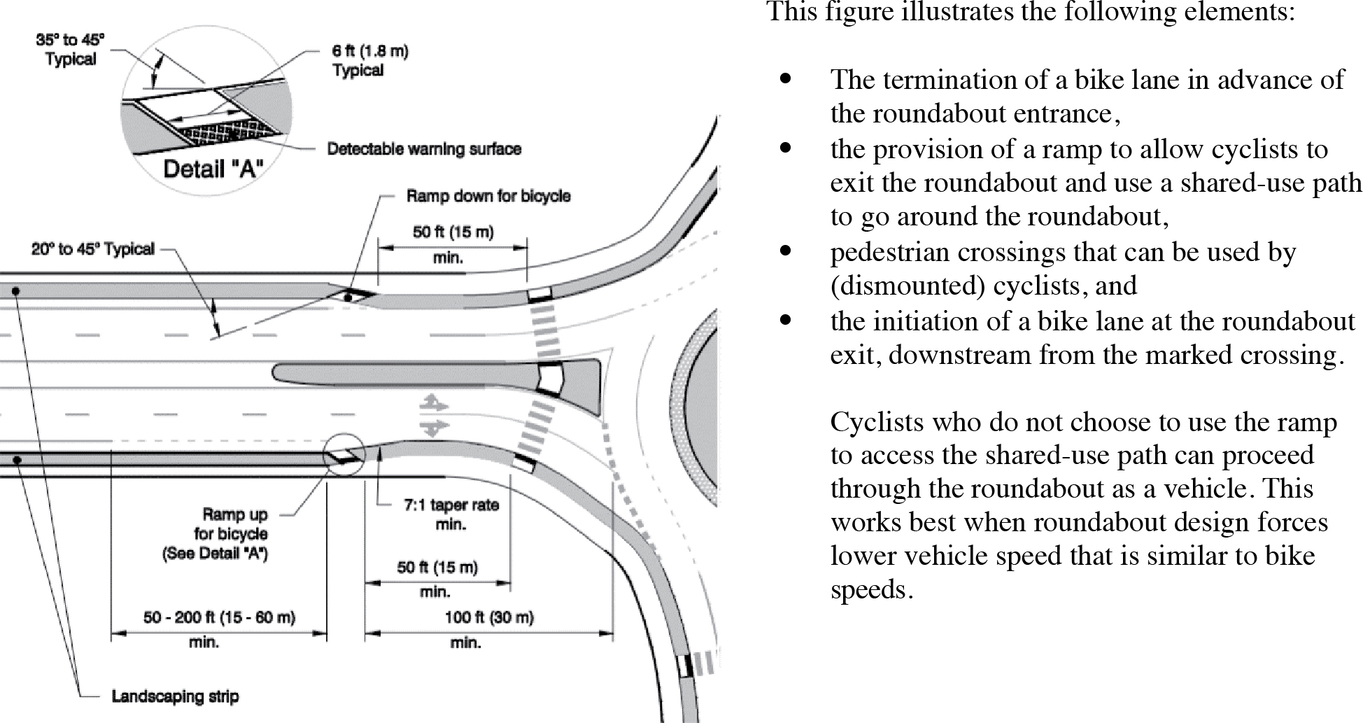
Source: Rodegerdts et al. (5).
Long Description.
The exit has a minimum of a 7 to 1 taper rate for a distance of 50 feet (15 meters), minimum. A ramp up for bicycle (detail A) is on one side and a ramp down for bicycle is on the opposite side. The angle of the ramp down for bicycle relative to the approach road is marked as typically 20 to 45 degrees. Landscaping strips are on either side of the exit. An enlarged image shows Detail A, depicting the ramp up for bicycle, with a 35 to 45 degree typical slope, 6 foot (1.8 meters) typical width, and detectable warning surface.
Discussion
Jensen (1) found that bicycle crashes increased at intersections converted to roundabouts for almost all bicycle facility types. The only facility to reduce bicycle crashes after the conversion was a separated cycle path with priority given to motorists, rather than bicycles, at the crossings on the roundabout approaches. The highest increase in bicycle crashes was seen at locations with a colored bicycle lane through the roundabout. Daniels et al. (2) found that roundabouts with cycle lanes perform worse than roundabouts with mixed traffic (no bicycle facility), separate cycle paths, or grade-separated cycle paths and that the severest bicycle crash types increased when previous intersections were converted to roundabouts regardless of the bicycle facility used.
Cumming (3) observed 130 individual cyclists at three roundabouts in Melbourne and found that cyclist behavior was potentially contributing to crashes, as nearly two-thirds of cyclists traveled on the outside of the lane—sometimes parallel with cars, while the other third traveled more of a straight-line path through the roundabout, cutting across the circulating lanes. Only five cyclists entered the circulating roundabout lane from the middle of the roundabout approach lane, but even these cyclists did not stay in that position throughout the roundabout. Cumming suggests strategies that (1) encourage cyclists to start in the center of the lane and remain there through the roundabout, (2) communicate the presence of cyclists to drivers, and (3) slow motor vehicle traffic are all key to maximizing cyclist visibility and reducing crashes. The National Association of City Transportation Officials (6) suggests one strategy for encouraging bicyclists to ride in the center of the lane is to provide sharrows within single or multilane roundabouts because bicycle lanes should not be provided within the roundabout (5, 7). This strategy should be used with caution, however, as the MUTCD does not explicitly address using sharrows in roundabouts. See also “Shared Use Lanes” (25-12).
Using a driving simulator, Jorgenson (4) found that driver behavior is more consistent at roundabouts without cycle facilities, and the time from when the circulating cyclist passes the merge point at the roundabout entrance to when the vehicle entering the roundabout arrives at the merge point is significantly less when cycle facilities are present. The study also found that drivers detected the presence of cyclists earlier where there were no cycle facilities, and that coloring the cycle lane blue or orange did not help drivers detect cyclists sooner (4).
Design Considerations
To better accommodate cyclists of all skill and comfort levels, designers should strive to design the roundabout for bicyclists to traverse either as a vehicle or as a pedestrian, especially where motor vehicle speeds and/or volumes are high. For bicyclists traveling as vehicles (which is best suited at locations where motor vehicle speeds are not substantially higher than bicycle speeds), bicycles should be forced to mix with traffic by terminating bike lanes at least 100 ft upstream of the yield line. For bicyclists who are less comfortable traveling in the circulatory roadway, a separate bicycle track or shared use path can be provided outside the roundabout. The roundabout design can include ramps to allow cyclists to move from the bike lane or shoulder onto the shared-use path. Care must be taken to prevent pedestrians with visual impairments from mistaking the bicycle ramps for a pedestrian crossing (8).
Cross References
Markings for Bicycles at Intersections
Key References
1. Jensen, S. U. (2013). Safety effects of converting intersections to roundabouts. Transportation Research Record: Journal of the Transportation Research Board, 2389, 22–29.
2. Daniels, S., Brijs, T., Nuyts, E., and Wets, G. (2009). Injury crashes with bicyclists at roundabouts: Influence of some location characteristics and the design of cycle facilities. Journal of Safety Research, 40(2), 141–148.
3. Cumming, B. (2012). High rate of crashes at roundabouts involving cyclists may be reduced with careful attention to conflict paths. Paper presented at the Australasian Road Safety Research Policing Education Conference, Wellington, New Zealand.
4. Jorgensen, B. L. C. L. (2009). Driver behavior toward circulating cyclists at roundabouts: Vehicle study with concurrent collection of eye movements. Paper presented at the Transportation Research Board 88th Annual Meeting, Washington, DC.
5. Rodegerdts, L., Bansen, J., Tiesler, C., Knudsen, J., Myers, E., Johnson, M., Moule, M., Persaud, B., Lyon, C., Hallmark, S., Isebrands, H., Crown, R. B., Guichet, B., and OʼBrien, A. (2010). NCHRP Report 672: Roundabouts: An Informational Guide. (2nd ed.). Transportation Research Board of the National Academies, Washington, DC.
6. National Association of City Transportation Officials. (2014). Urban Bikeway Design Guide (2nd ed.). New York, NY.
7. FHWA. (2023). Manual on Uniform Traffic Control Devices for Streets and Highways. (11th ed.). Washington, DC.
8. Jonsson, L., Hyden, C., and Svensson, A. (2007). Yielding behaviour and interaction at bicycle crossings. Paper presented at the 3rd Urban Street Symposium: Uptown, Downtown, or Small Town: Designing Urban Streets That Work, Seattle, WA.
GUIDE SIGNING AT ROUNDABOUTS
Introduction
While the use of roundabouts has grown rapidly in the United States in recent years, they remain unfamiliar to many road users. Drivers, pedestrians, and bicyclists may exhibit less confidence when navigating a roundabout than they do at a traditional intersection. Clear guidance is needed at all roundabouts to make the direction of travel clear. At multilane roundabouts, drivers need guidance to identify the correct path through the roundabout to reach their desired destination.
Advance-destination guide signs assist drivers in determining, prior to entering the roundabout, which lane to travel in and where to exit the roundabout, allowing them to focus more attention on the driving task and less attention on wayfinding. Drivers who have confidence in their position and path approaching, traveling through, and exiting the roundabout are less likely to perform erratic maneuvers or unexpected lane changes, which may improve safety for them and other road users around them. To supplement advance-destination guide signs, exit guide signs are recommended to indicate the destination of each exit from the roundabout. Exit guide signs can provide drivers with reassurance that they have selected their intended exit at the roundabout.


Discussion
Although roundabouts have become more common in the United States, drivers may still be relatively unsure about the proper way to navigate through them. This is largely because roundabouts involve high visual and perceptual demands due to the amount of information processing required (3). Drivers are presented with a relatively simple set of decisions at single-lane roundabouts—yield to driver on left, circulate to the right, decide where to exit. However, multilane roundabouts require additional decisions about lane selection and right-of-way allocation within the roundabout.
Signing is one of the most important tools designers can use to reduce driver workload and simplify driver understanding at roundabouts, particularly at multilane roundabouts (4). Signs can be used in advance of a roundabout to provide drivers with information about lane selection as well as the destination of each exit so that a driverʼs attention within the roundabout can be more focused on yielding and interacting with other vehicles. Driversʼ navigation through roundabouts is aided by clear, well-maintained pavement markings that correspond to diagrammatic signs.
The design and placement of signs is an important consideration when striving to simplify driver decision-making. Signs that consist of too much information or that are placed too closely together may result in driver distraction and information overload. In contrast, signs that consist of an appropriate amount of information and that are located appropriately will maximize the driverʼs ability to perform navigation, guidance, and vehicle control tasks. Johnson (3) recommends staging information delivery by separating lane use information (as shown in the sign on the left) and destination information (as shown in the sign on the right). He states that smaller signs and simplified information improve messaging to the driver, even if it requires using multiple signs to convey the information.

Source: MUTCD (1).
Long Description.
The first sign shows a curved left arrow with a dot in the middle and a curved left arrow with two legs pointing north and east. The second illustration shows a nearly circular arrow with three legs and names of locations.
Signing needs are different for urban and rural applications and for different categories of roundabouts and should be assessed on a case-by-case basis.
Design Considerations
NCHRP Report 672 provides recommendations on the placement of exit and departure signs (2):
For roundabouts involving the intersection of one or more numbered routes, route confirmation assemblies should be installed directly after the roundabout exit. . . . These assemblies should be located no more than 100 ft (30 m) beyond the intersection in urban areas and 200 ft (60 m) beyond the intersection in rural areas. Where there are pedestrian crossings on the exit leg, these signs should be placed after the crosswalk.
Cross References
Arrow-per-Lane Sign Design to Support Driver Navigation
General Principles for Sign Legends
Sign Design to Improve Legibility
Complexity of Sign Information
Key References
1. FHWA. (2023). Manual on Uniform Traffic Control Devices for Streets and Highways. (11th ed.). Washington, DC.
2. Rodegerdts, L., Bansen, J., Tiesler, C., Knudsen, J., Myers, E., Johnson, M., Moule, M., Persaud, B., Lyon, C., Hallmark, S., Isebrands, H., Crown, R. B., Guichet, B., and OʼBrien, A. (2010). NCHRP Report 672: Roundabouts: An Informational Guide. (2nd ed.). Transportation Research Board of the National Academies, Washington, DC.
3. Johnson, M. (2019). Safety impacts of signing and pavement markings on property-damage-only crashes at multi-lane roundabouts. Transportation Research Record: Journal of the Transportation Research Board, 2673, Washington, DC.
4. Kinzel, C. S. (2003). Signing and Pavement-Marking Strategies for Multi-Lane Roundabouts: An Informal Investigation. Paper presented at the 2nd Urban Street Symposium, Anaheim, CA.
ROUNDABOUT LIGHTING
Introduction
To safely navigate a roundabout, a driver must be able to clearly see the roundaboutʼs layout and understand its operations in sufficient time to make appropriate maneuvers, including yielding to pedestrians and accommodating cyclists. Lighting is used both to enhance the visibility of the roundabout from a distance and to improve the perception and visibility of the layout and other users for the driver during hours of low light and darkness. Lighting should be considered for use at every roundabout (1).
Agencies must determine how to provide cost-efficient lighting scenarios in order to light as many of their roundabouts as feasible. As with other intersection types, it can be costly to provide a power source in rural areas. Ecoluminance is a lighting technique that integrates lighting and vegetation to provide additional visual guidance at roadway features, including roundabouts. Ecoluminance generally uses overhead LED lamps and retroreflective elements. On the central island, landscape lighting and vegetation that can reflect light are used, while lights mounted on bollards (posts typically three to four feet tall) are used for pedestrian crossings. It can also be designed to provide additional visibility to roundabout features by using foliage to reflect light emitted from car headlamps, even in the absence of additional lighting. Ecoluminance has the potential to improve visibility while reducing long-term energy costs.


Renderings of Lighting Strategies at Roundabouts.
The image on the left illustrates using approach lighting to highlight pedestrian crossing (5). The image on the right illustrates using low-level light reflected off of foliage in the central island to highlight roadway geometry and pedestrian-height bollards to light pedestrian crossings (4).
Discussion
Lighting of roundabouts is important because headlights alone often cannot provide adequate illumination of the roundabout path due to the tight radius of the roundabout. When full lighting can be provided, the Illuminating Engineering Societyʼs Design Guide for Roundabout Lighting (now part of American National Standard Practice for Design and Maintenance of Roadways and Parking Facility Lighting) is considered the primary source for lighting design guidance (6). However, Rodgers et al. found that 68 to 83 percent of the benefits of full illumination at a roundabout could be achieved with partial illumination (2). When partial illumination is provided, the focus should be on lighting pedestrian crossings using either approach lighting in advance of the crosswalk or bollards with lights near the crosswalk to illuminate pedestrians from the front (rather than from directly above or behind) and on making the geometry of the roundabout clear to drivers. Ecoluminance is a strategy that can be employed that uses vegetation to reflect light to highlight roadway geometry (3, 4).
Headlights alone often cannot provide good illumination of the roundabout path due to the tight radius of the roundabout.
Design Considerations
It can often be difficult to bring a power source to rural roundabouts to provide traditional lighting fixtures. Nevertheless, while lighting is recommended at all roundabouts, it is especially critical at locations where pedestrians are expected and where traffic speeds are high, requiring more time to perceive and react to changes in roadway geometry.
Lighting fixtures may be located as far from the curb as possible and avoid locations where run-off-the-road crashes are more likely (1, 4).
Mowing and plowing operations should be considered when placing bollard-style fixtures and other low-level lighting fixtures. Ensure lighting fixtures are not placed where snow is expected to be deposited and stored in the winter (3).
Cross References
Countermeasures for Improving Pedestrian Conspicuity at Crosswalks
Characteristics of Lighting that Enhance Pedestrian Visibility
Characteristics of Effective Lighting at Intersections
Key References
1. Rodegerdts, L., Bansen, J., Tiesler, C., Knudsen, J., Myers, E., Johnson, M., Moule, M., Persaud, B., Lyon, C., Hallmark, S., Isebrands, H., Crown, R. B., Guichet, B., and OʼBrien, A. (2010). NCHRP Report 672: Roundabouts: An Informational Guide. (2nd ed.). Transportation Research Board of the National Academies, Washington, DC.
2. Rodgers, M. O., Hunter, M., Samoylov, A., Gbologah, F., and Berrebi, S. J. (2016). Evaluation of Current Practice for Illumination at Roundabouts: Safety and Illumination of Roundabouts (Phase I). Forest Park, GA: Georgia Department of Transportation.
3. Bullough, J. D. (2013). Ecoluminance: A new approach to visual guidance for roadways. International Journal of Sustainable Transportation, 8(2), pp. 127–150.
4. CTC and Associates. (2014). New approaches for roundabout lighting to enhance pedestrian safety. Transportation Research Synthesis 1413. Local Road Research Board: Minnesota Department of Transportation Research Services and Library.
5. Lutkevich, P., and Hasson, P. (2005). Transportation Research E-Circular E-C083: An Examination and Recommendation for Current Practices in Roundabout Lighting. Transportation Research Board of the National Academies, Washington, DC.
6. Illuminating Engineering Society. (2018). American National Standard Practice for Design and Maintenance of Roadway and Parking Facility Lighting. ANSI/IES Standard RP-8-18. Illuminating Engineering Society of North America, New York.


