Human Factors Guidelines for Road Systems: Third Edition (2025)
Chapter: 20 Lighting

COUNTERMEASURES FOR MITIGATING HEADLAMP GLARE
Introduction
Countermeasures for mitigating headlamp glare refers to road design elements that are effective for reducing the discomforting and disabling effects on visibility of exposure to glare from oncoming headlamps. The combination of high-intensity headlamps and high mounting heights in the vehicle fleet can result in greater exposure to glare for motorists. Several treatments are available for designing roadways that can reduce driversʼ exposure to glare.
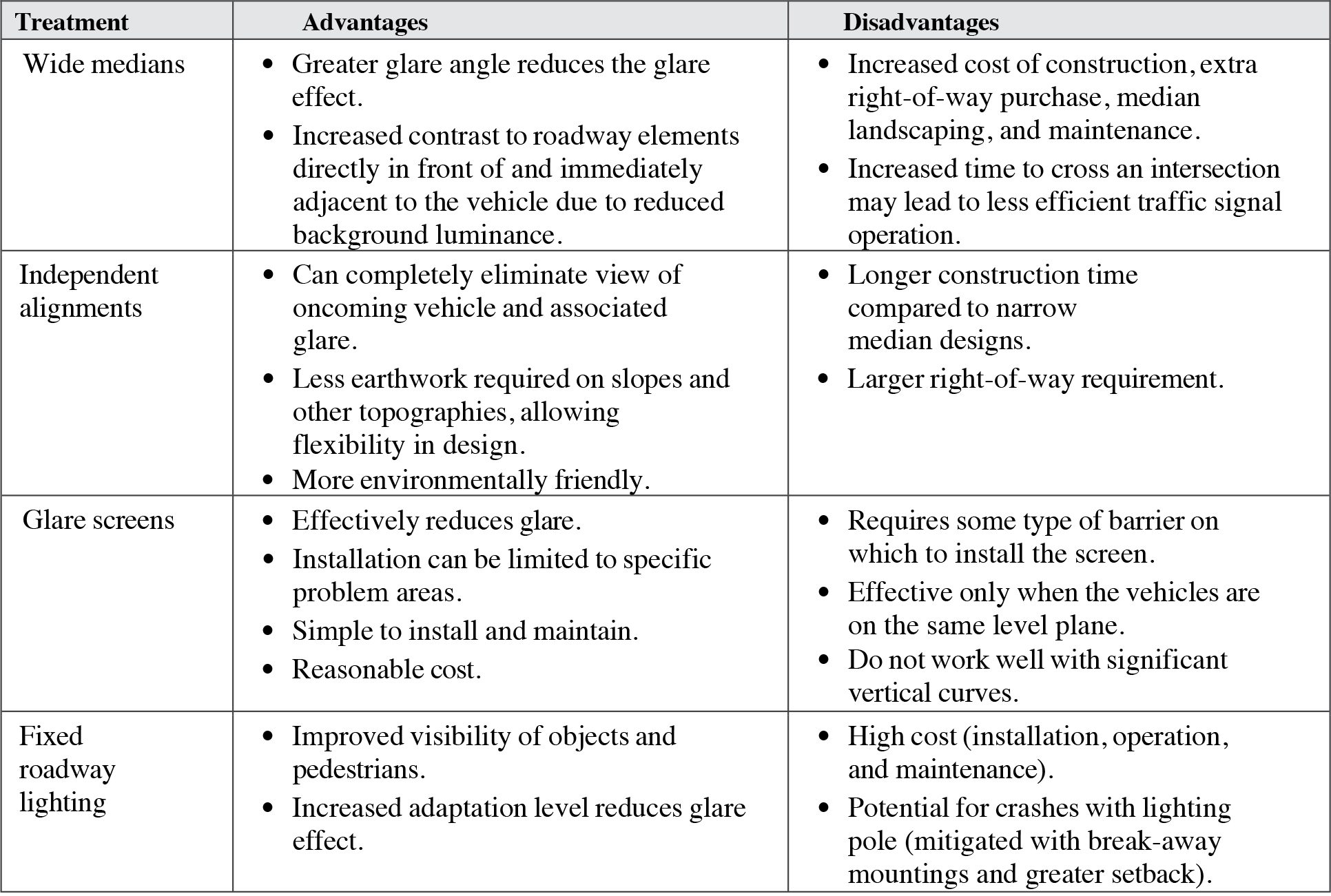

Long Description.
The angle of glare from the headlights of one vehicle toward the driver approaching from the opposite direction is shown.
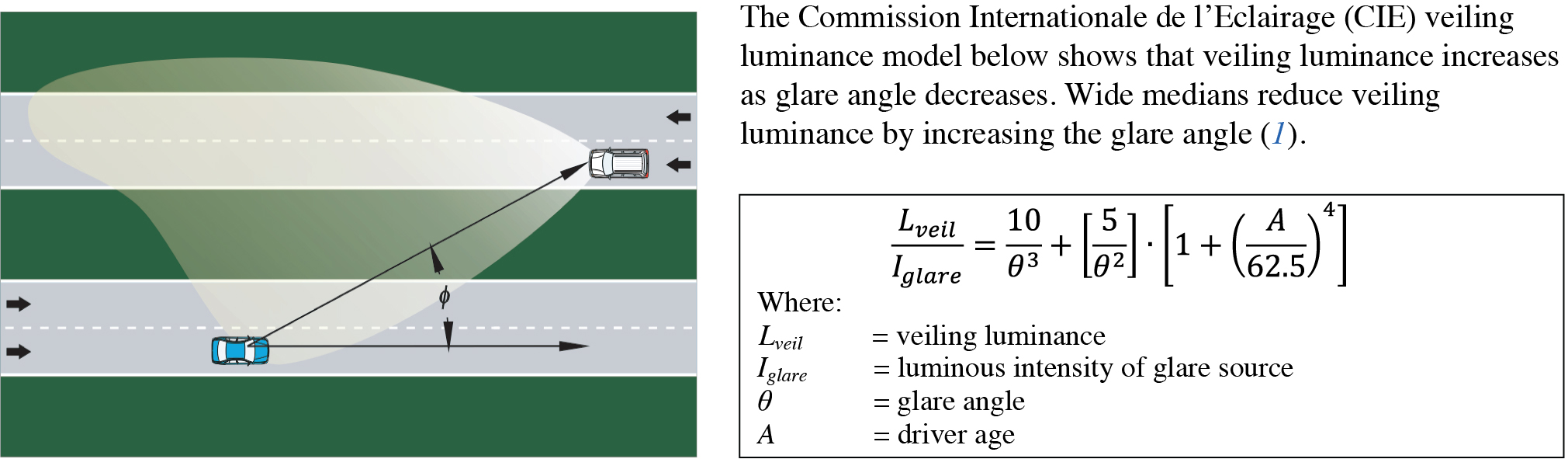
Long Description.
start fraction L subscript veil over I subscript glare end fraction equals start fraction 10 over theta superscript 3 end fraction plus open square bracket 5 over theta superscript 2 close square bracket multiplied by open square bracket 1 plus open parenthesis A over 62.5 close parenthesis superscript 4 close square bracket
Discussion
Glare occurs when the intensity of a light source within the visual field is substantially greater than the visual adaptation level, causing physical discomfort or pain (discomfort glare) and/or reduced visibility (disability glare). A portion of the light entering the eye is scattered in the transparent media of the eye (i.e., cornea, lens, and vitreous fluids) and by the tissues in the ocular fundus (2, 3). Some light also diffuses through the sclera and iris tissues. The scattered light superimposes a uniform veiling luminance onto the retinal image, reducing its overall contrast. If the contrast of an object falls below the contrast threshold under these conditions, it will be rendered invisible. Furthermore, transient adaptation caused by rapid changes in luminances within the visual field can cause further temporary reductions in contrast sensitivity and form perception (4). The amount of veiling luminance produced by headlamp glare is influenced primarily by headlamp characteristics—such as mounting height, beam pattern, and misaim—and by the angle at which the glaring luminance enters the eye.
Design Considerations
Several mathematical models have been developed that estimate the amount of veiling luminance developed by a glare source (e.g., 1, 5, 6). These models show that veiling luminance is inversely proportional to the angle at which the glaring luminance enters the eye relative to the forward gaze. Consequently, the glaring effects of exposure to light from oncoming headlamps can be significantly reduced by increasing the lateral separation of the opposing vehicles via wide median widths and independent alignments (7). Increasing the lateral distance between vehicles results in larger glare angles and therefore smaller veiling luminances. Independent alignments can separate vehicles both horizontally and vertically, and in some cases can eliminate exposure to oncoming glare altogether.
Other mitigations include the installation of glare screens (8) and fixed roadway lighting (7). Glare screens are devices used primarily in roadway medians to shield driversʼ eyes from exposure to glare from the headlights of oncoming vehicles. Typical glare screens consist of solid partitions (with or without intermittent openings), expanded metal mesh, knit polyester fabric, or vertical paddles oriented at an angle that blocks oncoming glare but allows lateral visibility. The cutoff angle for these types of glare screens is typically 20 degrees plus the degree of roadway curvature. Although no specific warrants have been established for installation of glare screens, many factors should be considered when determining whether to install these screens. These factors include nighttime crash rates (e.g., day-night ratio, average age of drivers in nighttime crashes, distribution of crash type, etc.), high traffic volume, public comments, high measured veiling luminance, road geometry, etc. Care must be given when designing and implementing glare screens in order to avoid limiting the sight distance in horizontal curves.
Fixed roadway lighting can reduce the effects of glare by: (1) increasing the visibility of objects and pedestrians and (2) increasing the overall adaptation level.
Cross References
Characteristics of Effective Lighting at Intersections
Key References
1. Commission Internationale de lʼEclairage. (2002). CIE Equations for Disability Glare. CIE 146:2002. Vienna, Austria.
2. Adrian, W., and Bhanji, A. (1991). Fundamentals of disability glare: A formula to describe straylight in the eye as a function of glare angle and age. Proceedings of the 1st International Symposium on Glare, 185–193.
3. Vos, J. J. (2003). On the cause of disability glare and its dependence on glare angle, age and ocular pigmentation. Clinical and Experimental Optometry, 86(6), 363–370.
4. Adrian, W., and Topalova, R. (1991). Transient adaptation process. A model to predict its effects on vision. Proceedings of the CIE 22nd Session 2, 121–133.
5. Bhise, V. D., Farber, E. I., Saunby, C. S., Troell, G. M., Walunas, J. B., and Bernstein, A. (1977). Modeling vision with headlights in a systems context. Society of Automotive Engineers International Automotive Engineering Congress and Exposition.
6. Farber, E., and Matle, C. (1989). PCDETECT: A revised version of the DETECT seeing distance model. Transportation Research Record: Journal of the Transportation Research Board,1213, 11–20.
7. Mace, D., Garvey, P., Porter, R., Schwab, R., and Adrian, W. (2001). Countermeasures for Reducing the Effects of Headlight Glare. Washington, DC: AAA Foundation for Traffic Safety.
8. Copas, T. L., and Pennock, H. A. (1979). NCHRP Synthesis 66: Glare Screen Guidelines. TRB, National Research Council, Washington, DC.
NIGHTTIME DRIVING
Introduction
This guideline provides information on the particular visibility challenges motorists face while driving in darkness on rural roads. The farthest distance at which drivers can see roadway features, objects in the roadway, or pedestrians ahead is limited by the headlamp intensity, ambient lighting, and presence or absence of oncoming headlamp glare. Often in rural driving, the ambient illumination is of such low intensity that it has little effect on visibility. Illumination of problem areas, along with appropriate signage, can play a significant role in improving safety when driving at night.

Discussion
Visibility during nighttime driving in rural environments can be challenging for drivers. Often there is little or no ambient lighting to enhance the illumination of the roadway or objects thereon. Visibility distance is limited to a threshold imposed by the luminous intensity of the headlamps, beyond which roadway features and objects or persons in the roadway are not visible due to insufficient contrast. Depending on headlamp characteristics and object reflectivity, visibility is generally limited to between 150 and 250 ft under clear, dry conditions (5, 6). However, the time required to react and stop under the best of conditions (i.e., short braking reaction time and hard deceleration) when driving at 55 mi/h can be 280 ft or more (7). Compounding this problem is the potential for increased stopping distance due to longer perception-reaction time caused by fatigue from prolonged rural driving.
Drivers often underappreciate the visual challenges associated with driving in darkness for several reasons. First, drivers believe they can safely drive at unsafe higher speeds because (a) there is sufficient light from the headlamps to support lane keeping, and (b) it is relatively easy to see road signs, edge lines, delineators, and other vehicles on the road (6). Also, the central vision required for hazard detection and recognition is severely degraded at distances beyond the visibility threshold of the headlamps (6). Drivers may not understand the illumination pattern of their own headlamps (i.e., that the illumination provided by the headlamp is heterogeneous) and may therefore misjudge the visibility distance within various regions of headlamp illumination (8). Speed limits that are uniform between day and night lead drivers to assume that driving at the speed limit is safe even though it may not be possible to stop within the visibility distance of the headlamp (9). Finally, drivers seldom use their high-beam headlamps, even in situations where there are no oncoming vehicles or vehicles in the lane ahead (10). Because of these factors, drivers often are likely to be unprepared for a dangerous encounter while driving in darkness.
Design Considerations
Fixed roadway illumination can improve visibility, reduce speed, and improve safety in rural areas that are identified as potentially hazardous or that have significant crash histories (e.g., 3, 4). Although lighting is the most effective mitigation for improving visibility, alternative treatments, such as signing, reflectors, and beacons, can enhance safety by reflecting more existing light to drivers or alerting drivers in advance of upcoming features.
The warrant criteria for installing continuous lighting is usually based on an analysis of cost-effectiveness, considering installation, operation, and maintenance costs in addition to the cost associated with crashes (2, 3). The warrant criteria vary widely between states and research sources and include factors such as average daily travel, crash frequency, and night-to-day crash ratio.
It may be appropriate to use a sign telling drivers to turn on their headlights when in the tunnel.
Cross References
Pavement Surface Countermeasures to Improve Curve Delineation
Sign Design to Improve Legibility
Key References
1. Brewer, M. A., and Fitzpatrick, K. (2004). Preliminary Evaluations of Safety Treatments on Rural Highways in Texas. College Station, Texas: Texas Transportation Institute.
2. Anderson, K. A., Hoppe, W. J., McCoy, P. T., and Price, R. E. (1984). Cost-effectiveness evaluation of rural intersection levels of illumination. Transportation Research Record: Journal of the Transportation Research Board, 996, 44–47.
3. Hallmark, S. L., Hawkins, N. R., Smadi, O., Kinsenbaw, C., Orellana, M., Hans, Z., and Isebrands, H. N. (2008). Strategies to Address Nighttime Crashes at Rural, Unsignalized Intersections. (IHRB Project TR-540; CTRE Project 05-220). Ames: Iowa State University Center for Transportation Research and Education.
4. Isebrands, H. N., Hallmark, S., Hans, Z., McDonald, T., Preston, H., and Storm, R. (2006). Safety Impacts of Street Lighting at Isolated Rural Intersections—Part II. (MN/RC-2006-35). St. Paul: Minnesota Department of Transportation.
5. Schiller, C., Sprute, H., Groh, A., Böll, M., and Khanh, T. Q. (2009). HID vs. Tungsten Halogen Headlamps: Driver Preferences and Visibility Distance (SAE Technical Paper 2009-01-0550). Warrendale, PA: Society of Automotive Engineers.
6. Owens, D. A., Francis, E. L., and Leibowitz, H. W. (1989). Visibility Distance with Headlights: A Functional Approach (Report No. 890684). Warrendale, PA: Society of Automotive Engineers.
7. Green, M. (2000). “How long does it take to stop?” Methodological analysis of driver perception-brake times. Transportation Human Factors, 2(3), 195–216.
8. Brooks, J. O., Goodenough, R. R., Tyrrell, R. A., Guirl, C., Moore, K., Klein, N., et al. (2009). How well do drivers understand their own headlights? Proceedings of the Fifth International Driving Symposium on Human Factors in Driver Assessment, Training and Vehicle Design, 384–390.
9. Leibowitz, H. W., Owens, D. A., and Tyrrell, R. A. (1998). Assured clear distance ahead rule: Implications for nighttime traffic safety and the law. Accident Analysis and Prevention, 30(1), 93–99.
10. Mefford, M. L., Flannagan, M. J., and Bogard, S. E. (2006). Real-World Use of High-Beam Headlamps. (UMTRI-2006-11). Ann Arbor: University of Michigan Transportation Research Institute.
DAYTIME LIGHTING REQUIREMENTS FOR TUNNEL ENTRANCE LIGHTING
Introduction
This guideline provides recommendations for minimum lighting requirements at the entrances of tunnels under daylight conditions in candela/meter squared. Visibility of low-visual-contrast objects can be challenging for drivers due to glare, large differences in illumination, and visual adaptation issues associated with the tunnel entrance. The guideline information below provides initial illumination recommendations that can be used during the initial tunnel design stage to promote better visibility when entering tunnels.

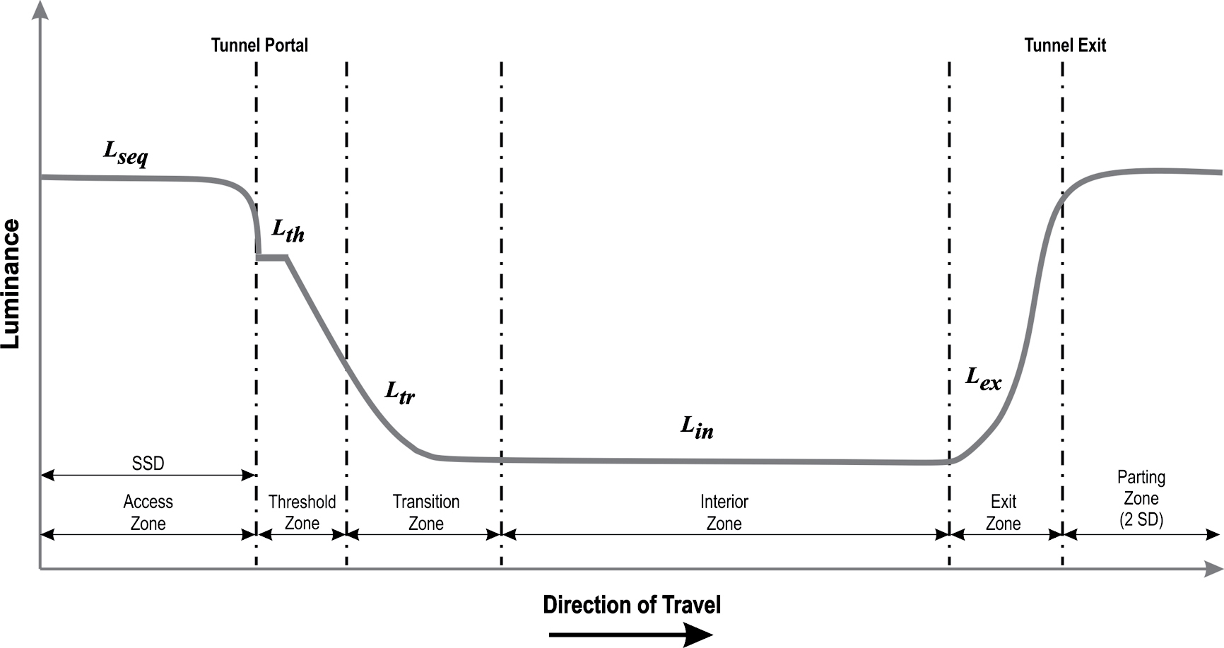
LIGHTING ZONES DURING TUNNEL APPROACH AND ENTRY
Source: Adapted from CIE (2).
Long Description.
The vertical axis shows luminance and the horizontal axis shows the direction of travel. The graph shows the access zone up to the tunnel portal, after which the following segments are labeled: threshold zone, transition zone, interior zone and exit zone, and then after the tunnel exit is a parting zone segment. The luminance curve decreases as it enters the tunnel, is constant through the interior zone, increases in the exit zone, and flattens out in the parting zone.
Discussion
Lighting of tunnel entrances requires special consideration because of how driversʼ visual systems respond to the unique lighting conditions that occur at these entrances. In particular, there are driver performance issues related to illumination levels in tunnel entrances. The first issue is that glare from the bright visual zones surrounding the tunnel entrance when lit by daylight can make objects within the entrance more difficult to see than if there was no glare (e.g., at night) (1, 2). This can significantly decrease the detection distance for hazards in the tunnel entrance. The second issue is related to the first in that large differences in illumination between the tunnel entrance and surrounding zones can cause the entrance to be perceived as a “black hole.” This can cause drivers to decelerate quickly or drive erratically and generally poses a safety risk (3). The third issue is visual adaptation, which occurs when drivers transition from the high light levels outside the tunnel to dimmer interior tunnel lighting (4). Driversʼ sensitivity to low-visual-contrast hazards is generally reduced until their eyes are able to adapt to the lower light levels, leading to a corresponding decrease in detection distance. In most cases, driversʼ eyes have sufficient time to make this adjustment before entering the tunnel. This issue, however, may require special consideration if posted speeds are high, which gives drivers less time to adapt to lower lighting conditions.
Design Considerations
Vehicle speed approaching the tunnel is an important consideration. Since drivers are assumed to be adapting to lower light levels as they approach the tunnel entrance, their travel speed affects the amount of time their eyes have to adjust to tunnel entrance illumination. At higher speeds, drivers will have less time to adjust (e.g., 13 s vs. 6.5 s for 40 and 80 km/h posted speeds, respectively), and significantly higher levels of tunnel illumination will be required to maintain adequate visibility (1). Consequently, if posted speeds approaching the tunnel are changed, then lighting requirements should be formally reexamined.
The sky is a significant source of daytime luminance, and the amount of sky in driversʼ field of view during the approach to a tunnel entrance can lead to an elevated adaptation level prior to entering the tunnel (1). The topography of the area surrounding the tunnel often affects the amount of sky that is visible, with flat topographies exposing large regions of sky and therefore substantial luminances in the field of view, which elevates adaptation level. In general, the more sky that is visible in the field of view prior to tunnel entry, the higher the surface luminance that is required in the tunnel entrance in order to maintain adequate visibility. Greater surface luminance is also required when large, bright surfaces surround the tunnel entrance (e.g., large retaining walls, rocks, and other highly reflective surfaces).
Tunnel lighting requirements can be defined with regard to a common visual task (e.g., 2). Specifically, this involves the detection of a hazard in the middle of the driverʼs lane and requires that drivers be able to stop before reaching the hazard. In the CIE calculations for determining lighting requirements, the target is assumed to have a height and width of 20 cm and a reflectivity of 20%. The ray between the driver eye point (assumed to be 1.5 m above the roadway) and a low hazard on the road is the basis for computing the effect of the luminance of peripheral visual zones on driver visibility and adaptation.
Counterbeam lighting appears to be more effective in making potential hazards easier to see because it increases the objectʼs contrast relative to the background (3). The IESNA guidelines (1) suggest that lighting requirements can be reduced if counterbeam lighting is used in the transition zone.
Regardless of the type of lighting configuration, AASHTO (5) recommends that the lighting should be as continuous as possible to minimize the stroboscopic effect produced by the alternating bright/dark spacing of the luminaires. When driving at the design speed, visual frequencies of 5 to 10 cycles per second have been shown to cause eye annoyance and should be avoided.
Cross References
Countermeasures for Mitigating Headlamp Glare
Characteristics of Effective Lighting at Intersections
Key References
1. Illuminating Engineering Society of North America. (2005). IESNA Recommended Practice for Tunnel Lighting. ANSI/IES RP-22. New York.
2. Commission Internationale de lʼEclairage. (2004). Guide for the Lighting of Road Tunnels and Underpasses. CIE 88:2004. Vienna, Austria.
3. Blaser, P. (1990). Counterbeam lighting, a proven alternative for the lighting of the entrance zones of road tunnels. Transportation Research Record: Journal of the Transportation Research Board, 1287, 244–251.
4. Adrian, W. K., and Topalova, R. V. (1991). Visibility under transient adaptation. Transportation Research Record: Journal of the Transportation Research Board, 1327, 14–20.
5. AASHTO. (2018). Roadway Lighting Design Guide. (4th ed.) Washington, DC.
COUNTERMEASURES FOR IMPROVING PEDESTRIAN CONSPICUITY AT CROSSWALKS
Introduction
Countermeasures for improving pedestrian conspicuity at crosswalks refers to treatments that use flashing lights and beacons at midblock and intersection crosswalks. These lighting treatments do not necessarily improve visibility of pedestrians; rather, they are used to alert drivers to the presence of pedestrians in the crosswalk. The MUTCD (1) provides standards for implementing in-roadway warning lights, flashing beacons, and flashing LEDs mounted in pedestrian crossing signs (rapid flashing beacons). This guideline provides additional information for the effective use of these countermeasures.

EXAMPLES OF IN-PAVEMENT FLASHING LIGHTS, IN-SIGN FLASHING LIGHTS, AND SIGN-MOUNTED FLASHING BEACONS
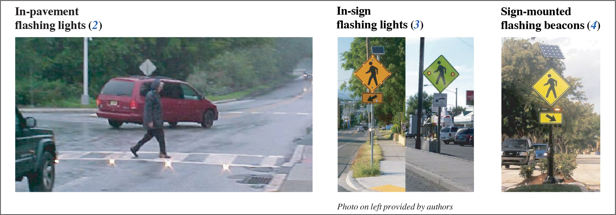
Long Description.
The first photo shows in-pavement flashing lights along a crosswalk. No road signs marking the crosswalk are visible. The second image consists of two photos, each of which depicts a diamond-shaped crosswalk sign with flashing lights, below which is a sign with an arrow pointing to the crosswalk. The first photo has flashing lights on each corner and along each side of the sign, while the second photo has only two flashing lights. The third image shows a diamond-shaped crosswalk sign, below which is a flashing beacon and a sign with an arrow pointing to the crosswalk.
Discussion
In-roadway flashing lights, sign-mounted flashing beacons, and flashing LEDs mounted in “Pedestrian Crossing” warning signs (in-sign flashing lights) have been shown to improve the safety at pedestrian crosswalks. These treatments are designed to alert drivers to the presence of pedestrians in the crosswalks or to make the crosswalk itself more conspicuous. When these treatments are used to supplement signs and markings at crosswalks, they have been shown to reduce the number of evasive conflicts between drivers and pedestrians (4), increase the rate of motoristsʼ yielding to pedestrians (4, 5), increase the distance at which drivers apply their brakes (5), reduce motoristsʼ approach speed (6), and increase pedestriansʼ perception of safety (7) in both day and nighttime driving.
In-roadway flashing lights can be an attractive alternative to full signalization when the conditions are appropriate. The greatest improvements in safety generally occur in crosswalks with high pedestrian usage on roads with high average daily traffic. One source (8) recommends that in-pavement flashing lights be used when at least 100 pedestrians per day use the crosswalk and when average daily traffic (ADT) is between 5,000 and 30,000 vehicles per day. In-pavement systems, however, can be expensive to acquire, install, and maintain relative to other treatments. Consequently, some jurisdictions (e.g., 9) recommend that in-roadway flashing lights be used only when more traditional treatments prove unsuccessful at sufficiently improving safety. In-sign flashing LEDs or sign-mounted flashing beacons may provide successful, lower cost alternatives to in-pavement flashing lights for crosswalks with lower ADT or pedestrian density.
Dramatic improvements in driver behavior near crosswalks have been demonstrated when sign-mounted flashing beacons or in-sign flashing lights are used in combination with in-pavement flashing lights. In one study (3) almost 90% of vehicles yielded to pedestrians when in-pavement flashers and sign-mounted beacons were both present, 70% yielded with in-sign flashers only, and 18–25% yielded when there was no treatment. Similarly, another study (6) showed marked reductions in vehicle speed, pedestrian wait time, curb-to-curb duration of crossing, and disregarding pedestrians in the crosswalk when in-pavement flashing lights were used in concert with sign-mounted flashing beacons.
Design Considerations
To differentiate between an empty crosswalk and one with pedestrians present, in-pavement flashing lights should be active only when pedestrians are present in the crosswalk (1). Drivers who are repeatedly exposed to continually flashing lights may become accustomed to them and eventually ignore them, particularly if the crosswalk is usually empty when they encounter it. Flashing lights can be activated either manually by pressing a pushbutton that indicates intent to cross, or automatically using sensors (passive detection) at the crosswalk entrances. Passive detection is generally preferred over using a manual pushbutton because some pedestrians may not bother to press a pushbutton before crossing or they may be confused by the pushbutton because there is no corresponding signal indicating when to walk (8). However, this confusion can be mitigated by including signage to indicate the purpose of the pushbutton, such as “Press button for crosswalk warning lights” (3).
Because in-roadway flashing lights protrude above the street surface, they can present a potential safety hazard to bicyclists (5). Careful placement of the markers where bicyclists (or motorcyclists) are not likely to ride and minimizing the height of protrusion should reduce this hazard.
Overhead lighting intended to support pedestrians may also improve safety performance at crosswalks.
Cross References
Characteristics of Lighting that Enhance Pedestrian Visibility
Methods to Increase Driver Yielding at Uncontrolled Crosswalks
Key References
1. FHWA. (2023). Manual on Uniform Traffic Control Devices for Streets and Highways. (11th ed.) Washington, DC.
2. Van Derlofske, J., Boyce, P. R., and Gilson, C. H. (2003). Evaluation of in-pavement, flashing warning lights on pedestrian crosswalk safety. 82nd Annual Meeting of the Transportation Research Board.
3. Davis, K. D., and Hallenbeck, M. E. (2008). Evaluation of Engineering Treatments and Pedestrian and Motorist Behavior on Major Arterials in Washington State (WA-RD 707.1). Olympia: Washington State Department of Transportation.
4. Van Houten, R., Ellis, R., and Marmolejo, E. (2008). Stutter-flash light-emitting-diode beacons to increase yielding to pedestrians at crosswalks. Transportation Research Record: Journal of the Transportation Research Board, 2073, 69–78.
5. Godfrey, D., and Mazzella, T. (1999). Success in redesigning main streets for pedestrians. Proceedings of the Sixth National Conference on Transportation Planning for Small and Medium-Sized Communities. Retrieved from https://rosap.ntl.bts.gov/view/dot/12751
6. Prevedouros, P. D. (2001). Evaluation of In-Pavement Flashing Lights on a Six-Lane Arterial Pedestrian Crossing.
7. Ullman, B., Fitzpatrick, K., and Trout, N. (2004). On-street pedestrian surveys of pedestrian crossing treatments. Proceedings of the ITE 2004 Annual Meeting and Exhibit.
8. Whitlock and Weinberger Transportation. (1998). An Evaluation of a Crosswalk Warning System Utilizing In-Pavement Flashing Lights. Retrieved June 20, 2011 from http://www.safezonealert.com.au/files/EvaluationCrosswalkWarningSystemUtilizingInPavementLights.pdf
9. Arnold, E. D., Jr. (2004). Development of Guidelines for In-Roadway Warning Lights. Final report (VTRC 05-R10). Charlottesville: Virginia Transportation Research Council.
CHARACTERISTICS OF LIGHTING THAT ENHANCE PEDESTRIAN VISIBILITY
Introduction
This guideline addresses characteristics of luminaires at midblock and intersection crosswalks as well as for general street lighting that will enhance the visibility of pedestrians in or near the roadway. Factors that affect visibility under street lighting include intensity and color spectrum of the light source, reflectivity and color of the pedestrian clothing, reflectivity of the road surface, and whether the pedestrian is seen with peripheral or foveal vision. The characteristics addressed in this guideline include spectral power distribution (color) of the light source and luminaire location. Intensity of the light is an important characteristic that is covered in “Characteristics of Effective Lighting at Intersections” on page 20-12.

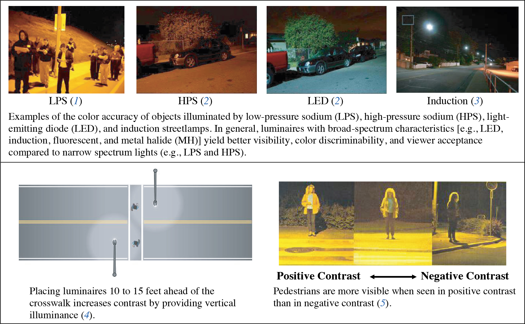
Long Description.
The first, second, third, and fourth images are photos showing LPS (1), HPS (2), LED (2), and Induction (3). The different types of lights affect the color accuracy of objects they illuminate in the photos. The fifth image is a rendering of a road with the luminaires placed 10 to 15 feet ahead of the crosswalk. The sixth, seventh, and eighth images are photos of a pedestrian that show the range from positive contrast to negative contrast.
Discussion
The issues associated with visibility of pedestrians at night under street lighting are complex. Drivers must detect pedestrians under mesopic lighting levels, at which both the rod and cone receptors in the retina support vision (6). The peak sensitivity of the cones occurs in the yellow region of the spectrum, while the rod peak sensitivity is near the blue/green. In mesopic lighting, visual sensitivity is shifted toward the blue/green portion of the visible spectrum compared to vision under photopic (daytime) lighting, when the cones are the primary visual receptors. However, pedestrian detection often relies on peripheral vision, which is dominated by the rods, causing even further bias toward the blue. Consequently, the spectral power distribution (SPD) of the light source can have a considerable effect on the visibility of a pedestrian depending on clothing color and position relative to the driverʼs forward gaze. Clothing that is similar in color to the lighting source is more highly visible than clothing of a contrasting color (e.g., under yellow light, a yellow shirt will appear to be brighter than a blue shirt will). This suggests that a broad-spectrum light source will likely promote superior visibility for pedestrians wearing a variety of colors.
Various lamp technologies exhibit different spectral characteristics: MH lamps cast a bluish light, while high- and low-pressure sodium lamps are biased toward the yellow portion of the spectrum. The SPD of the light source has been shown to affect pedestrian visibility. In one study (7), detection distances were similar for pedestrians wearing white clothing under both HPS and MH lamp sources. However, detection distances were greater with MH lamps than with HPS lamps when pedestrians were wearing denim. White fabric reflects all colors somewhat equally, so it is less sensitive than blue denim to spectral bias in the light source. In contrast, denim reflects the blue light of the MH lamps while it absorbs much of the yellow from an HPS lamp. Newer technologies, such as LED, fluorescent, and induction lamps, are likely to result in better visibility over a broader range of clothing colors because these lamps generally can be designed to have broad spectral distributions. One study (8) demonstrated that detection distances were longer when using several LED and induction lamp systems compared to a lower wattage HPS lamp even though the HPS illuminance was greater than any of the alternative lamp types.
Color contrast can also play a role in improving visibility. Lighting a crosswalk with lamps of a color spectrum that differs from the overall road lighting can draw attention to the crosswalk and improve motoristsʼ brightness perception, concentration, and search behavior through the crossing area (9).
Design Considerations
Pedestrians are more visible in positive contrast (i.e., the background is darker than the pedestrian) than they are in negative contrast (i.e., the background is lighter than the pedestrian) (5). Luminaires placed 10 to 15 ft ahead of a crosswalk can improve contrast by providing vertical illuminance incident on the pedestrian that is stronger than the horizontal illuminance incident on the pavement behind the pedestrian (10, 11). Bollard-mounted lights can also provide high-contrast vertical luminance at a crosswalk. In a lighting simulation (10), bollard-mounted luminaires were effective for providing superior vertical illumination for visibility of pedestrians, but they also were found to be more glaring than more traditional illumination methods. Regardless of the luminaire type, the system should be carefully designed to minimize driversʼ exposure to glare from the luminaire.
Cross References
Characteristics of Effective Lighting at Intersections
Key References
1. Mutmansky, M., Givler, T., Garcia, J., and Clanton, N. (2010). Advanced Street Lighting Technologies Assessment Project—City of San Jose. Boulder, CO: Clanton and Associates.
2. Energy Solutions. (2008). Demonstration Assessment of Light Emitting Diode (LED) Street Lighting. Host Site: City of Oakland, California. Washington, DC: Department of Energy.
3. Morante, P. (2008). Mesopic Street Lighting Demonstration and Evaluation Final Report. Groton, Connecticut: Groton Utilities.
4. Gibbons, R. B., Edwards, C. J., Williams, B., and Andersen, C. K. (2008). Informational Report on Lighting Design for Midblock Crosswalks (FHWA-HRT-08-053). McLean, VA: FHWA.
5. Hasson, P., Lutkevich, P., Ananthanarayanan, B., Watson, P., Knoblauch, R., and Nitzburg, M. (2002). Field test for lighting to improve safety at pedestrian crosswalks. Proceedings of the 16th Biennial Symposium on Visibility and Simulation.
6. Lewin, I. (1999). Lamp Color and Visibility in Outdoor Lighting Design, developed from a paper delivered to the 1999 Conference of the Institution of Lighting Engineers, Portsmouth, England.
7. Edwards, C. J., and Gibbons, R. B. (2008). Relationship of vertical illuminance to pedestrian visibility in crosswalks. Transportation Research Record: Journal of the Transportation Research Board, 2056, 9–16.
8. Gibbons, R. B., Edwards, C. J., Clanton, N., and Mutmansky, M. (2010). Alternative lighting evaluations: Municipality of Anchorage. 90th Annual Meeting of the Transportation Research Board.
9. Janoff, M. S., Freedman, M., and Koth, B. (1977). Driver and pedestrian behavior—The effect of specialized crosswalk illumination. Journal of the Illuminating Engineering Society, 6(4), 202–208.
10. Bullough, J. D., Zhang, X., Skinner, N. P., and Rea, M. S. (2009). Design and Evaluation of Effective Crosswalk Illumination. (FHWA-NJDOT-2009-003). Trenton: New Jersey Department of Transportation.
11. Chu, X. (2006). Pedestrian Safety at Midblock Locations. (CUTR BD544-16). Tallahassee: Florida Department of Transportation.
CHARACTERISTICS OF EFFECTIVE LIGHTING AT INTERSECTIONS
Introduction
Characteristics of effective lighting at intersections refers to lighting characteristics that facilitate visibility at intersections while avoiding detrimental effects of glare from luminaires. Although vehicle headlamps provide some measure of illumination, additional fixed lighting is often required to provide light levels and contrast that are satisfactory for safe visibility at intersections. This guideline provides principles for improving visibility of pedestrians, vehicles, roadway features, and obstacles at intersections.

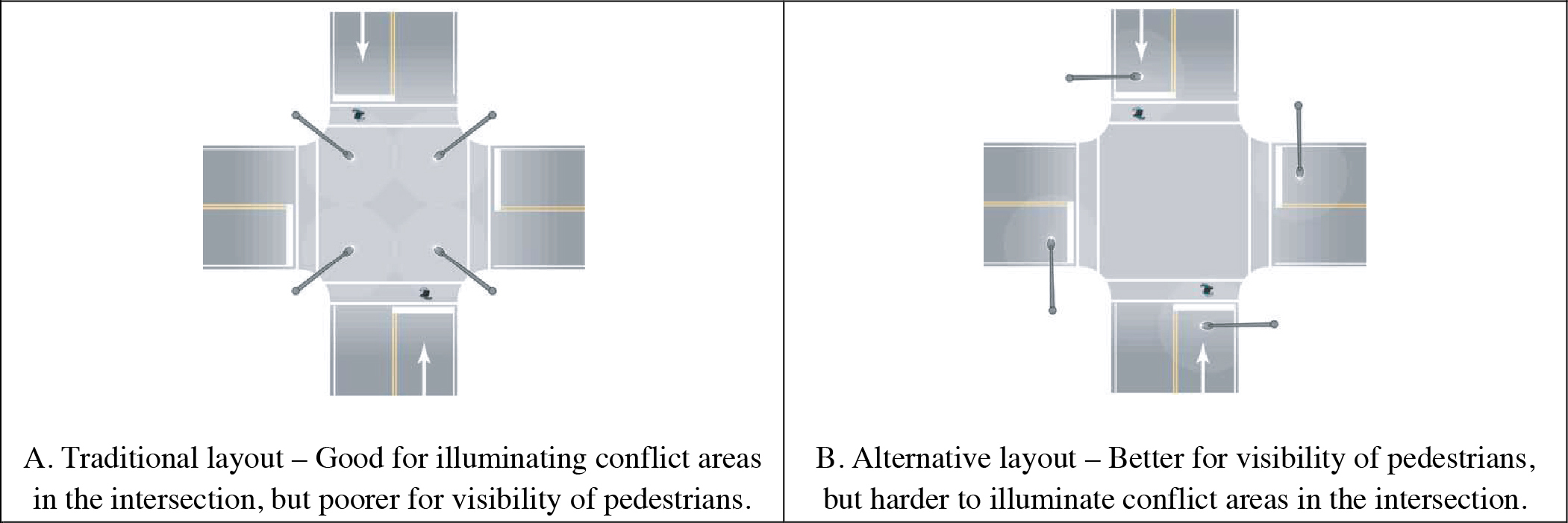
Source: Gibbons et al. (2).
Long Description.
Illustration A shows the traditional layout. It is good for illuminating conflict areas at intersections, but poorer for the visibility of pedestrians. Illustration B shows the alternative layout. It offers better visibility of pedestrians, but makes it harder to illuminate conflict areas at the intersection.
Discussion
A minimum level of illumination is required in the driving environment for drivers to visually detect pedestrians, obstructions, intersection features, and other vehicles in order to safely cross or turn at an intersection at night. Although vehicle headlamps provide some measure of illumination, additional fixed lighting is often required to provide light levels and contrast that are satisfactory for visibility at intersections. Most sources agree that the addition of illumination at an intersection increases visibility and enhances safety (e.g., 3, 4, 5), and studies have shown that in some rural intersections as few as one or two luminaires can provide safety benefits (3, 6). Luminaires are relatively expensive to install and maintain, however, and warranting criteria for the installation of lighting vary widely between jurisdictions. Nonetheless, well-designed lighting at critical intersections can be cost-effective when considering the cost of crashes against the operating costs of the lighting. In one study (7), it was estimated that the payback for the addition of lighting would occur within as little as one year using HPS lighting (although HPS is not the lighting source preferred by drivers, visibility is still likely to be better with HPS than with no lighting). One methodological approach (8) for warranting illumination of isolated rural intersections is based on geometric, operational, environmental, and collision factors and uses ratings and weights to assess if full or partial illumination is warranted. The critical factors determining the need for illumination are traffic volumes, nighttime collisions attributable to lack of lighting, and the extent of raised channelization.
Design Considerations
Three methods are described in the RP-8-00 standards (1) for the measurement and specification of light levels from roadway luminaires: (a) the luminance method, (b) the illuminance method, and (c) the small target visibility method. Each of these methods has advantages and disadvantages. The luminance method measures the light reflected from the road surface to the driverʼs eye. This method is preferred by some jurisdictions (e.g., 9) for measuring tangent sections because it directly measures the light that the eye sees. However, the luminance method is impractical for use at intersections because the elevated lighting levels at the intersection skew the average luminance value used in the veiling luminance calculations (9). Likewise, the small target visibility method requires veiling luminance calculations to determine adaptation luminance. The illuminance method is suitable for designing lighting at intersections because it measures the amount of light incident on the roadway surface and is therefore independent of the observer and road reflectance properties.
The luminaire mast height, in combination with the beam pattern of the light source, affects the coverage, uniformity, and intensity of the illuminance measured at the pavement. Higher mast heights generally provide better coverage (e.g., more uniformity over a larger area) but at the expense of intensity. The results of a simulated lighting study (10) suggest that, to optimize lighting levels and coverage, a preferred lighting configuration includes luminaires with 50-foot mast heights. These luminaires should be mounted as close as possible to both intersecting centerlines in the intersection without entering into any clear zone. However, one disadvantage of a taller mast is exposing drivers to glare. Luminaire and geometric characteristics (e.g., luminaire cutoff pattern, vertical curvature approaching the intersection, etc.) should be considered when designing both the mast height and the lighting in general.
Cross References
Characteristics of Lighting that Enhance Pedestrian Visibility
Key References
1. Illuminating Engineering Society of North America. (2000). American National Standard Practice for Roadway Lighting (RP-8-00 Reaffirmed 2005). ANSI/IESNA RP-8-00. New York.
2. Gibbons, R. B., Edwards, C. J., Williams, B., and Andersen, C. K. (2008). Informational Report on Lighting Design for Midblock Crosswalks (FHWA-HRT-08-053). McLean, VA: FHWA.
3. Green, E. R., Agent, K. R., Barrett, M. L., and Pigman, J. G. (2003). Roadway Lighting and Driver Safety. (KTC-03-12/SPR247-02-1F). Lexington: Kentucky Transportation Center.
4. Isebrands, H. N., Hallmark, S., Hans, Z., McDonald, T., Preston, H., and Storm, R. (2006). Safety Impacts of Street Lighting at Isolated Rural Intersections—Part II. (MN/RC-2006-35). St. Paul: Minnesota Department of Transportation.
5. Hallmark, S. L., Hawkins, N. R., Smadi, O., Kinsenbaw, C., Orellana, M., Hans, Z., and Isebrands, H. N. (2008). Strategies to Address Nighttime Crashes at Rural, Unsignalized Intersections. (IHRB Project TR-540; CTRE Project 05-220). Iowa State Univ. Center for Transportation Research and Education.
6. Rockwell, T. H., Bala, K. N., and Hungerford, J. C. (1976). A Comparison of Lighting, Signing, and Pavement Marking Methods for Detecting Rural Intersections at Night. (OHIO-DOT-08-76). Columbus: Ohio State University.
7. Box, P. C. (1989). Major road accident reduction by illumination. Transportation Research Record: Journal of the Transportation Research Board, 1247, 32–38.
8. Gibbs, M., Shaflik, C., and Zein, S. (2001). Illumination of Isolated Rural Intersections. Ottawa: Transportation Association of Canada.
9. McCormick Rankin Corporation (MRC) and Gabriel Design. (2009). Right-of-way Lighting Policy (Document No. 21-10). Ottawa, Ontario: City of Ottawa.
10. Kinzenbaw, C. (2007). Effectiveness of intersection lighting. 2007 Transportation Scholars Conference. Ames: Iowa State University.


